


USER'S GUIDE
Vaisala CARBOCAP® Hand-Held
Carbon Dioxide Meter
GM70
M010139EN-G
PUBLISHED BY |
|
|
|
Vaisala Oyj |
Phone (int.): |
+358 |
9 8949 1 |
P.O. Box 26 |
Fax: |
+358 |
9 8949 2227 |
FI-00421 Helsinki |
|
|
|
Finland |
|
|
|
Visit our Internet pages at www.vaisala.com.
© Vaisala 2012
No part of this manual may be reproduced, published or publicly displayed in any form or by any means, electronic or mechanical (including photocopying), nor may its contents be modified, translated, adapted, sold or disclosed to a third party without prior written permission of the copyright holder. Translated manuals and translated portions of multilingual documents are based on the original English versions. In ambiguous cases, the English versions are applicable, not the translations.
The contents of this manual are subject to change without prior notice.
This manual does not create any legally binding obligations for Vaisala towards customers or end users. All legally binding obligations and agreements are included exclusively in the applicable supply contract or the General Conditions of Sale and General Conditions of Service of Vaisala.
___________________________________________________________________
Table of Contents |
|
CHAPTER 1 |
|
GENERAL INFORMATION....................................................... |
9 |
About This Manual ................................................. |
9 |
Contents of This Manual ...................................... |
9 |
Version Information ............................................ |
10 |
Documentation Conventions .............................. |
10 |
Safety..................................................................... |
10 |
ESD Protection................................................... |
11 |
Recycling............................................................... |
11 |
Trademarks ........................................................... |
11 |
License Agreement .............................................. |
12 |
Warranty................................................................ |
12 |
CHAPTER 2 |
|
PRODUCT OVERVIEW .......................................................... |
13 |
Introduction to Vaisala CARBOCAP® |
|
Hand-Held Carbon Dioxide Meter GM70............. |
13 |
Basic Features of the GM70............................... |
13 |
Interchangeable Probes ..................................... |
14 |
Tool for Adjustments .......................................... |
14 |
Parts Description.................................................. |
15 |
Probes ................................................................... |
16 |
GM70PUMP for Aspirated Sampling ................... |
16 |
CHAPTER 3 |
|
PREPARATIONS BEFORE USE............................................ |
17 |
Recharging the Batteries ..................................... |
17 |
Turning On and Setting Language, Date, and |
|
Time ....................................................................... |
18 |
CHAPTER 4 |
|
MEASURING CARBON DIOXIDE .......................................... |
19 |
Taking Measurements |
|
(Diffusion Sampling With GMH70 Handle).......... |
19 |
Taking Measurements |
|
(Pump Aspirated Sampling With GM70PUMP)... |
20 |
Measuring Other Parameters Simultaneously ... |
22 |
VAISALA ___________________________________________________________3
USER'S GUIDE ______________________________________________________
CHAPTER 5 |
|
BUTTONS, DISPLAYS, AND MENUS .................................... |
23 |
Buttons and Navigation........................................ |
23 |
Basic Display......................................................... |
24 |
Graphical Display.................................................. |
25 |
Menus..................................................................... |
25 |
CHAPTER 6 |
|
SETTINGS............................................................................... |
27 |
Setting Actual Pressure Value and Unit.............. |
27 |
Setting Actual Temperature Value and Unit ....... |
28 |
Display Settings .................................................... |
29 |
Display Units....................................................... |
29 |
Rounding ............................................................ |
30 |
Hold/Save Display .............................................. |
30 |
Graphic History ................................................... |
30 |
User Interface ........................................................ |
31 |
Selecting ............................................................. |
31 |
Automatic Power Off........................................... |
32 |
Changing the Shortcut Keys ............................... |
32 |
Key Click and Backlight On Key Press ............... |
33 |
Setting Date and Time ........................................ |
33 |
Device Information................................................ |
34 |
Reverting Factory Settings.................................. |
35 |
Other Settings ....................................................... |
35 |
Setting the Alarm Levels ..................................... |
35 |
CHAPTER 7 |
|
ANALOG OUTPUT CONNECTION......................................... |
37 |
Selecting and Scaling the Analog Output........... |
37 |
CHAPTER 8 |
|
RECORDING DATA ................................................................ |
39 |
Recording .............................................................. |
39 |
Stopping Recording.............................................. |
40 |
Viewing Recorded Data ........................................ |
41 |
Checking Memory Status ..................................... |
41 |
Deleting All Recorded Files.................................. |
41 |
Transferring Recorded Data to PC ...................... |
42 |
4 ______________________________________________________ M010139EN-G
___________________________________________________________________
CHAPTER 9 |
|
FIELD CHECKING OF FIXED TRANSMITTERS.................... |
43 |
Field Checking of the Vaisala GMW115 and |
|
GMD/W20 Series Transmitters |
|
(Diffusion Sampling)............................................. |
43 |
Field Checking of the Vaisala GMD/W20 Series |
|
Transmitters (Pump Aspirated Sampling) .......... |
45 |
Field Checking of the GMT220 or GMM220 |
|
(Without a Display) ............................................... |
46 |
CHAPTER 10 |
|
CALIBRATING AND ADJUSTING THE PROBES ................. |
47 |
Calibration Interval ............................................... |
47 |
Factory Calibration and Adjustment................... |
47 |
Calibration and Adjustment by the User ............ |
48 |
Adjustment with Reference Gases...................... |
49 |
Equipment Needed............................................. |
49 |
Reference Gases ............................................... |
49 |
Two-Point Adjustment Procedure....................... |
49 |
One-Point Adjustment Procedure....................... |
51 |
Adjustment with Two Probes .............................. |
53 |
CHAPTER 11 |
|
ERROR MESSAGES .............................................................. |
55 |
CHAPTER 12 |
|
MAINTENANCE...................................................................... |
57 |
Changing the Probe.............................................. |
57 |
Changing the Probe Filter.................................... |
58 |
Cleaning ................................................................ |
58 |
Changing the Battery Pack .................................. |
59 |
Technical Support ................................................ |
60 |
Product Returns ................................................... |
60 |
VAISALA ___________________________________________________________5
USER'S GUIDE ______________________________________________________
CHAPTER 13 |
|
TECHNICAL DATA ................................................................. |
61 |
GM70 Hand-Held Carbon Dioxide Meter ............. |
61 |
General ............................................................... |
61 |
Electromagnetic Compatibility............................. |
61 |
GMP221/222 Probes.............................................. |
61 |
GMH70 Handle, GM70PUMP................................. |
63 |
MI70 Indicator........................................................ |
63 |
Indicator General ................................................ |
63 |
Battery Pack ....................................................... |
64 |
Accessories........................................................... |
65 |
Dimensions in mm (inch) ..................................... |
66 |
6 ______________________________________________________ M010139EN-G
___________________________________________________________________
List of Figures |
|
|
Figure 1 |
GM70 Parts ............................................................ |
15 |
Figure 2 |
Properly Connecting the GM70PUMP .................... |
21 |
Figure 3 |
Example of the Display when the Carbon Dioxide, |
|
|
and the Temperature and Humidity Probe are |
|
|
Connected Simultaneously to the MI70 Indicator ... |
22 |
Figure 4 |
MI70 Indicator Buttons............................................ |
23 |
Figure 5 |
Basic Display .......................................................... |
24 |
Figure 6 |
Menus..................................................................... |
26 |
Figure 7 |
Environment Menu ................................................. |
27 |
Figure 8 |
Display Menu.......................................................... |
29 |
Figure 9 |
User Interface Settings Menus ............................... |
31 |
Figure 10 |
Changing the Shortcut Keys ................................... |
33 |
Figure 11 |
Device Information Displays ................................... |
34 |
Figure 12 |
Other Settings Menu............................................... |
35 |
Figure 13 |
Selecting Analog Output......................................... |
37 |
Figure 14 |
Recording Data....................................................... |
39 |
Figure 15 |
Location of the MI70 Connector Ports .................... |
43 |
Figure 16 |
Location of the Adjustment Button.......................... |
48 |
Figure 17 |
Field Check Adapter ............................................... |
50 |
Figure 18 |
Detaching the Probe............................................... |
57 |
Figure 19 |
Installing the Battery Pack ...................................... |
59 |
Figure 20 |
Dimensions............................................................. |
66 |
List of Tables |
|
|
Table 1 |
Manual Revisions ................................................... |
10 |
Table 2 |
GMP221 and GMP222 Measuring Ranges ............ |
16 |
Table 3 |
Error Messages Table ............................................ |
55 |
Table 4 |
General Specifications............................................ |
61 |
Table 5 |
Measuring Ranges ................................................. |
61 |
Table 6 |
Accuracy Specifications.......................................... |
62 |
Table 7 |
Other Specifications ............................................... |
62 |
Table 8 |
General Specifications............................................ |
63 |
Table 9 |
General Specifications............................................ |
63 |
Table 10 |
Battery Pack Specifications .................................... |
64 |
Table 11 |
Accessories Table .................................................. |
65 |
VAISALA ___________________________________________________________7
USER'S GUIDE ______________________________________________________
This page intentionally left blank.
8 ______________________________________________________ M010139EN-G
Chapter 1 ___________________________________________ General Information
CHAPTER 1
GENERAL INFORMATION
This chapter provides general notes about this manual and the Product.
About This Manual
This manual provides information for installing, operating, and maintaining Vaisala CARBOCAP® Hand-Held Carbon Dioxide Meter GM70.
Contents of This Manual
This manual consists of the following chapters:
-Chapter 1, General Information, provides general notes about this manual and the Product.
-Chapter 2, Product Overview, introduces the features, advantages, and the product nomenclature.
-Chapter 3, Preparations Before Use, describes the procedures required before use.
-Chapter 4, Measuring Carbon Dioxide, consists of instructions on how to do carbon dioxide measurements.
-Chapter 5, Buttons, Displays, and Menus, contains information about the buttons, displays and menus of the GM70.
-Chapter 6, Settings, provides information about the settings of GM70.
-Chapter 7, Analog Output Connection, describes the selecting and scaling of the analog output connection.
-Chapter 8, Recording Data, describes the recording, viewing and transferring of data.
-Chapter 9, Field Checking of Fixed Transmitters, describes the field checking of fixed transmitters.
-Chapter 10, Calibrating and Adjusting the Probes, contains information on calibrating and adjusting the probes.
-Chapter 11, Error Messages, lists the error messages of the GM70.
VAISALA ___________________________________________________________9
USER'S GUIDE ______________________________________________________
-Chapter 12, Maintenance, consists of maintenance and technical support information.
-Chapter 13, Technical Data, provides the technical data of the GM70.
Version Information
Table 1 |
Manual Revisions |
|
|
|
|
Manual Code |
Description |
|
M010139EN-G |
April 2012. This version. New error codes |
|
|
|
added. General updates implemented. |
M010139EN-F |
2008. Previous version. |
|
|
|
Documentation Conventions |
|
|
|
Throughout the manual, important safety considerations are highlighted |
|
|
|
as follows: |
|
|
|
|
|
|
WARNING |
Warning alerts you to a serious hazard. If you do not read and follow |
|
|
|
instructions very carefully at this point, there is a risk of injury or even |
|
|
|
death. |
|
|
|
|
|
|
|
|
|
CAUTION |
Caution warns you of a potential hazard. If you do not read and follow |
|
instructions carefully at this point, the product could be damaged or |
|
important data could be lost. |
|
|
NOTE |
Note highlights important information on using the product. |
|
|
Safety
|
The Vaisala CARBOCAP® Hand-Held Carbon Dioxide Meter GM70 |
|
delivered to you has been tested for safety and approved as shipped from |
|
the factory. Note the following precautions: |
|
|
CAUTION |
Do not modify the unit. Improper modification can damage the product |
|
or lead to malfunction. |
|
|
10 _____________________________________________________ M010139EN-G
Chapter 1 ___________________________________________ General Information
ESD Protection
Electrostatic Discharge (ESD) can cause immediate or latent damage to electronic circuits. Vaisala products are adequately protected against ESD for their intended use. It is possible to damage the product, however, by delivering electrostatic discharges when touching, removing, or inserting any objects inside the equipment housing.
To make sure you are not delivering high static voltages yourself:
-Handle ESD sensitive components on a properly grounded and protected ESD workbench.
-When an ESD workbench is not available, ground yourself to the equipment chassis with a wrist strap and a resistive connection cord.
-If you are unable to take either of the above precautions, touch a conductive part of the equipment chassis with your other hand before touching ESD sensitive components.
-Always hold component boards by the edges and avoid touching the component contacts.
Recycling
Recycle all applicable material.
Dispose of batteries and the unit according to statutory regulations. Do not dispose of with regular household refuse.
Trademarks
Vaisala CARBOCAP® is a registered trademark of Vaisala Oyj.
Windows® is a registered trademark of Microsoft Corporation in the
United States and/or other countries.
VAISALA __________________________________________________________ 11
USER'S GUIDE ______________________________________________________
License Agreement
All rights to any software are held by Vaisala or third parties. The customer is allowed to use the software only to the extent that is provided by the applicable supply contract or Software License Agreement.
Warranty
Visit our Internet pages for standard warranty terms and conditions:
http://www.vaisala.com/warranty.
Please observe that any such warranty may not be valid in case of damage due to normal wear and tear, exceptional operating conditions, negligent handling or installation, or unauthorized modifications. Please see the applicable supply contract or Conditions of Sale for details of the warranty for each product.
12 _____________________________________________________ M010139EN-G
Chapter 2 _____________________________________________ Product Overview
CHAPTER 2
PRODUCT OVERVIEW
This chapter introduces the features, advantages, and the product nomenclature.
Introduction to Vaisala CARBOCAP® HandHeld Carbon Dioxide Meter GM70
The GM70 hand-held carbon dioxide meter measures volume concentration of CO2 gas and displays the result in the units of ppm or percentage %. The exceptional stability and reliability performance of the GM70 comes from the advanced silicon based Vaisala CARBOCAP® sensor.
Basic Features of the GM70
-Both numerical and graphical displays
-Data logging possibility
-Tool for checking the reading of fixed CO2 transmitters
-Tool for adjusting Vaisala GMP220 series probes
-Possibility for an analog output (voltage signal 0 ... 1 V)
-Sampling methods: diffusion sampling (GMH70 handle) or pump aspirated sampling (GM70PUMP), alternatively
-An optional, ready-to-use Microsoft Windows® software (MI70LINK), which allows an easy way to handle measurement data using a serial line or a USB instrument cable
VAISALA __________________________________________________________ 13
USER'S GUIDE ______________________________________________________
Interchangeable Probes
By selecting the right probe you can choose the measuring range that best fits for your application. The calibrated measuring ranges varies from 0...2000 ppm to 0 ... 20% concentrations of CO2. Refer to Chapter 2, Product Overview, on page 13 and Chapter 13, Technical Data, on page 61 for more details. For changing the measuring range you only have to change the probe.
Tool for Adjustments
For adjusting the GMT220 series transmitters or GMM220 series modules, the GM70 needs only the GMP220 probes. GM70 adjusts and stores the adjusting information to the nonvolatile memory of the probes. This enables true interchangeability of the probes.
14 _____________________________________________________ M010139EN-G
Chapter 2 _____________________________________________ Product Overview
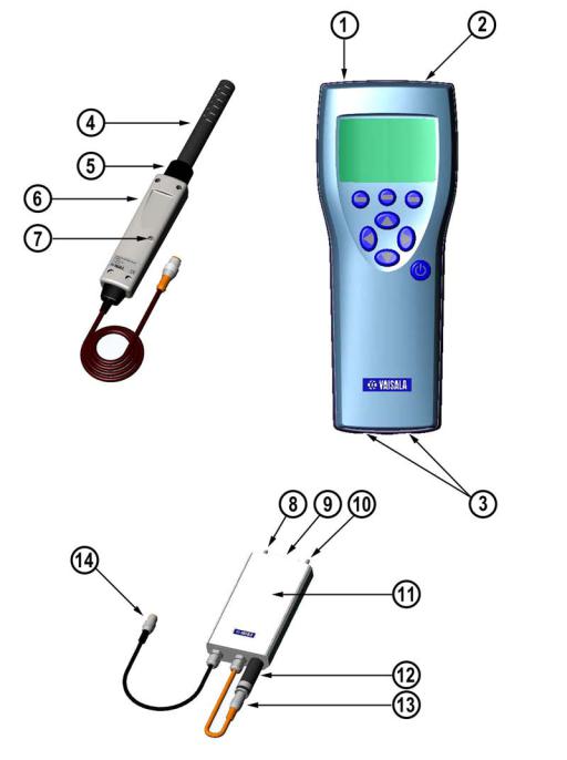
Parts Description
0505-221
Figure 1 |
GM70 Parts |
The following numbers refer to Figure 1 above:
1= MI70 indicator
2= Recharger connector
3= Connector ports I and II for probes and cables
VAISALA __________________________________________________________ 15
USER'S GUIDE ______________________________________________________
4= Probe GMP221 or GMP222
5= Probe fastener
6= Handle GMH70
7= Adjustment button
8= Gas outlet
9= ON/OFF switch
10= Gas inlet
11= Measuring chamber
12= Probe GMP221 or GMP222
13= Probe connector
14= Connector to MI70 indicator
Probes
The GMP220 series probes can be used with the GM70. Table 2 below presents the measuring ranges that can be can be selected for the probes.
Table 2 |
GMP221 and GMP222 Measuring Ranges |
|
|||||
|
|
|
|
|
|
||
|
Probe |
|
Measuring Range |
|
|
||
|
GMP221 |
|
0 ... |
2%, 0 ... |
3%, 0 |
... 5%, 0 ... |
10%, 0 ... |
|
|
|
20% CO2 |
|
|
|
|
|
GMP222 |
|
0 ... |
2000 ppm, 0 ... |
3000 ppm, 0 5000... |
||
|
|
|
... ...ppm, 0 7000 ppm, 0 10000 ppm |
||||
In order to obtain the best possible performance, it is recommended that the measurement range is chosen so that the actual concentrations to be measured are roughly in the middle of the measuring range.
GM70PUMP for Aspirated Sampling
GM70 aspiration pump consists of a pump and a measurement chamber for CO2 measurements. GM70PUMP is designed for checking of fixed CO2 transmitters and for sampling from locations difficult to access.
GM70PUMP is connected to a MI70 indicator which displays the measurement result. Pump system is powered through the MI70 indicator.
16 _____________________________________________________ M010139EN-G
Chapter 3 ________________________________________Preparations Before Use
CHAPTER 3
PREPARATIONS BEFORE USE
This chapter describes the procedures required before use.
Recharging the Batteries
1.If using alkaline batteries, unscrew the back plate of the indicator and insert the batteries. Note that while possible, the use of alkaline batteries is not recommended. If the GM70 is ordered with a rechargeable battery pack, the battery pack is already in place as shipped from the factory.
2.Recharge the battery pack as follows: Plug in recharger to the recharger connector of the indicator and connect the recharger to wall socket. A battery symbol in corner of display starts to roll.
-It is not recommended to use the GM70 during the first recharging. Later on the GM70 can be used while recharging.
-Duration of recharging depends on the charge level of the battery pack being 4 hours typical. The recommended first recharging time is 6 hours.
3.The battery pack is full when the battery symbol stops to roll.
4.Disconnect the recharger.
VAISALA __________________________________________________________ 17

USER'S GUIDE ______________________________________________________
Turning On and Setting Language, Date,
and Time
1.Connect the probe handle (or the connector from the GM70PUMP) to either of the connector ports of the indicator.
2.Press the  button.
3.Select the language by using 
 buttons. Confirm by pressing
 SELECT.
4.The default date presentation format is: date.month.year. To change the date, select Date and press  SET. Change the date by using the


 buttons. To confirm the date, press
  OK. If you want to change the format, select M/D/Y date format (month/date/year), press
  ON.
ON.
5.The default time presentation format is 24-hour clock. To change
the time, select Time and press  SET. Change the time by using arrow buttons. To confirm the time, press
  OK. If you want to use 12-hour clock, select 12-hour clock, press
  ON.
ON.
6.Press  EXIT. To check and change the environment settings, select YES. Otherwise select NO, basic display appears.
7.To ensure the best possible accuracy set the actual pressure and temperature values to the GM70 as follows:
-Select the pressure setting (P: 1013 hPa, default), press  UNIT to select unit (hPa or bar), press
  SET, set the pressure value by using arrow buttons. Press
  OK to save the value.
-Select the temperature setting (T: 25.0 C°, default), press  UNIT to select unit (°C or °F), press
  SET, set the temperature value by using arrow buttons. Press +/- to change the sign of the value. Press
  OK to save the value.
8.Press  EXIT to return to the basic display.
18 _____________________________________________________ M010139EN-G
Chapter 4 ______________________________________ Measuring Carbon Dioxide
CHAPTER 4
MEASURING CARBON DIOXIDE
This chapter consists of instructions on how to do carbon dioxide measurements.
The results of carbon dioxide measurements are affected by the air pressure and the temperature of the measurement conditions. For achieving the most accurate measurements in high altitudes where the barometric pressure is clearly lower than in the sea level, the actual atmospheric pressure value should be set to the GM70. The acceptable pressure value range is 700 ... 1300 hPa.
NOTE
Before measurements ensure that the air pressure and temperature settings are correct. Set the correct settings as instructed in section Setting Actual Pressure Value and Unit on page 27.
Taking Measurements (Diffusion Sampling
With GMH70 Handle)
See Chapter 3 Preparations Before Use on page 17 if you start the GM70 for the first time, otherwise follow the instructions below:
1.Connect the probe cable to the MI70 indicator's connector port.
2.Press  POWER ON/OFF button.
3.Wait for about 15 seconds to get the reading. For the most accurate readings wait for 15 minutes to reach the full operating state of the GM70.
4.Install the probe to the measuring position. Avoid exhaling near the probe as this increases the CO2 concentration.
5.The basic display opens, allow the reading to stabilize.
VAISALA __________________________________________________________ 19
USER'S GUIDE ______________________________________________________
CAUTION |
Handle the probe carefully. Strong impact or falling can damage the |
|
|
probe. |
|
|
If you need to disconnect the probe, first press |
POWER ON/OFF button to |
turn the indicator OFF. This ensures that all settings and data are saved properly.
Taking Measurements (Pump Aspirated
Sampling With GM70PUMP)
See Chapter 3 Preparations Before Use on page 17 if you start the GM70 for the first time, otherwise follow the instructions below:
1.Connect one end of the sampling tube to the gas inlet (marked with IN), in case of using a tube.
2.Connect the black cable of the GM70PUMP to the MI70 indicator's connector port.
3.Plug in the recharger connector of the MI70 and connect the recharger to wall socket.
4.Connect the GM220 probe to the probe connector of the GM70PUMP.
5.Insert the probe in the measuring chamber. Note that to have a tight installation, the two O-rings on the opening of the measuring chamber should not match together with the filter edge or the tapes on the probe (see Figure 2 on page 21). When operating the pump, especially when taking a sample from hot and humid conditions into room temperature, take care that no condensation forms on the probe.
6.Install the other end of the sampling tube to the sampling location.
7.Turn on the MI70 indicator by pressing the  button.
8.Turn on the GM70PUMP.
9.The basic display opens.
10.Wait for a few minutes to get a stabilized reading. For the most accurate readings wait for 15 minutes to reach the full operating state of the GM70.
20 _____________________________________________________ M010139EN-G
Chapter 4 ______________________________________ Measuring Carbon Dioxide
0505-222
Figure 2 Properly Connecting the GM70PUMP
The following number refers to Figure 2 above:
1= Match the 2 O-rings together with the smooth probe surface to have a tight connection!
NOTE |
Only one pump aspirated system can be connected to the MI70 at a time. |
|
|
|
|
NOTE |
When using the pump aspirated system it is recommended to power the |
|
system by using the recharger connected to a wall socket. |
|
|
NOTE |
The battery indicator of the MI70 display does NOT show the actual |
|
recharge level when the pump is in operation. |
|
|
VAISALA __________________________________________________________ 21
 Loading...