


Weather Sensor
FD12P
USER'S GUIDE
M210296en-A
May 2002
PUBLISHED BY |
|
|
|
Vaisala Oyj |
Phone (int.): |
+358 |
9 8949 1 |
P.O. Box 26 |
Fax: |
+358 |
9 8949 2227 |
FIN-00421 Helsinki |
|
|
|
Finland |
|
|
|
Visit our Internet pages at http://www.vaisala.com/
© Vaisala 2002
No part of this manual may be reproduced in any form or by any means, electronic or mechanical (including photocopying), nor may its contents be communicated to a third party without prior written permission of the copyright holder.
The contents are subject to change without prior notice.
Please observe that this manual does not create any legally binding obligations for Vaisala towards the customer or end user. All legally binding commitments and agreements are included exclusively in the applicable supply contract or Conditions of Sale.
_________________________________________________________________________________
Table of Contents |
|
CHAPTER 1 |
|
GENERAL INFORMATION .......................................................................... |
11 |
About This Manual.................................................................. |
11 |
Contents of This Manual...................................................... |
11 |
Version Information................................................................ |
12 |
Related Manuals ..................................................................... |
12 |
Safety ....................................................................................... |
12 |
General Safety Considerations............................................ |
12 |
Product Related Safety Precautions ................................... |
13 |
Safety Summary............................................................. |
13 |
Ground the Equipment ................................................... |
13 |
Radio Frequency Interference Statement (USA) ........... |
15 |
ESD Protection .................................................................... |
15 |
Trademarks ............................................................................. |
16 |
Warranty .................................................................................. |
16 |
CHAPTER 2 |
|
PRODUCT OVERVIEW ................................................................................ |
17 |
Introduction............................................................................. |
17 |
Hardware Structure ............................................................. |
17 |
Sensing Elements .......................................................... |
19 |
Electronics Enclosure..................................................... |
20 |
Structural Elements ........................................................ |
20 |
Operating Principle .............................................................. |
21 |
Using FD12P ....................................................................... |
22 |
Equipment Nomenclature ...................................................... |
23 |
Specifications ......................................................................... |
24 |
Mechanical Specifications ................................................... |
24 |
Electrical Specifications....................................................... |
24 |
Optical Specifications .......................................................... |
25 |
Capabilities and Limitations.................................................. |
26 |
Visibility Measurement Specifications ................................. |
26 |
Weather Sensing Specifications.......................................... |
26 |
Environmental Specifications .............................................. |
27 |
CHAPTER 3 |
|
INSTALLATION............................................................................................ |
29 |
Organizing Installation........................................................... |
29 |
Location and Orientation ....................................................... |
30 |
Grounding and Lightning Protection.................................... |
32 |
Equipment Grounding.......................................................... |
32 |
Internal Grounding............................................................... |
34 |
VAISALA _________________________________________________________________________ 3
User's Guide _______________________________________________________________________
Grounding for Testing Purposes......................................... |
34 |
Grounding Remote Units and Communication Cable......... |
34 |
Cable Selection ...................................................................... |
35 |
Line Power Cabling............................................................. |
35 |
Communication Cable......................................................... |
35 |
Unloading and Unpacking..................................................... |
36 |
Unpacking Procedure ......................................................... |
36 |
Storage Information ............................................................ |
36 |
Installation Procedures ......................................................... |
37 |
Constructing the Foundation............................................... |
37 |
Mounting When Casting the Pad................................... |
38 |
Mounting to an Existing Surface.................................... |
38 |
Assembling the FD12P ....................................................... |
40 |
Attaching the DTS14B Temperature Sensor to the Mast ... |
41 |
Connecting Cables.............................................................. |
43 |
Basic Wiring................................................................... |
43 |
Communication Cable EMC-shielding........................... |
46 |
Connecting a Background Luminance Sensor or a |
|
Day/Night Switch to FD12P ........................................... |
48 |
Communication Options ..................................................... |
50 |
Serial Communications Settings.................................... |
50 |
Serial Transmission RS-232.......................................... |
50 |
Serial Multipoint Transmission RS-485 ......................... |
51 |
Modem DMX21.............................................................. |
52 |
Indicators and Manual Controls..................................... |
54 |
Indicators .................................................................. |
54 |
Manual Controls ....................................................... |
54 |
Analog Transmission ..................................................... |
55 |
Connecting the Maintenance Terminal.......................... |
55 |
Startup Testing.................................................................... |
56 |
Initial Settings...................................................................... |
56 |
CHAPTER 4 |
|
OPERATION ................................................................................................ |
59 |
Introduction ............................................................................ |
59 |
User Commands in Normal Operation................................. |
59 |
Markings Used in This Manual ............................................. |
61 |
Entering/Exiting the Command Mode.................................. |
61 |
OPEN Command ................................................................ |
61 |
CLOSE Command .............................................................. |
62 |
Automatic Message Sending................................................ |
62 |
Message Types................................................................... |
63 |
Message 0 ..................................................................... |
64 |
Message 1 ..................................................................... |
64 |
Message 2 ..................................................................... |
65 |
Message 3 ..................................................................... |
65 |
Message 4 ..................................................................... |
66 |
Messages 5 and 6 ......................................................... |
66 |
Message 7 ..................................................................... |
68 |
Message Polling..................................................................... |
69 |
FD12P Command Set............................................................. |
70 |
HELP Command................................................................. |
70 |
4 ______________________________________________________ M210296en-A
_________________________________________________________________________________
MES Command ................................................................... |
71 |
AMES Command............................................................ |
71 |
Weather Related Commands .............................................. |
73 |
WPAR Command ........................................................... |
73 |
WSET Command ........................................................... |
73 |
Precipitation Limit...................................................... |
74 |
Weather Update Delay.............................................. |
74 |
Haze Limit ................................................................. |
74 |
Rain Intensity Scale................................................... |
75 |
Violent Rain Limit ...................................................... |
75 |
Heavy Rain Limit ....................................................... |
75 |
Light Rain Limit.......................................................... |
75 |
Drizzle Limit............................................................... |
75 |
Heavy Drizzle Limit.................................................... |
76 |
Light Drizzle Limit...................................................... |
76 |
Snow Limit................................................................. |
76 |
Heavy Snow Limit...................................................... |
76 |
Light Snow Limit........................................................ |
76 |
Snow Pellets Limit..................................................... |
77 |
Snow Grains Limit ..................................................... |
77 |
Ice Crystals Limit....................................................... |
77 |
Hail Limit.................................................................... |
77 |
DRD Scale................................................................. |
77 |
Warm Limit ................................................................ |
77 |
PRW Command.............................................................. |
77 |
CLRS Command ............................................................ |
78 |
WHIS Command............................................................. |
78 |
System Configuration Commands....................................... |
79 |
PAR Command............................................................... |
79 |
CONF Command............................................................ |
80 |
BAUD Command............................................................ |
84 |
BLSC Command............................................................. |
84 |
Maintenance Commands..................................................... |
85 |
STA Command............................................................... |
85 |
CAL Command............................................................... |
87 |
TCAL Command............................................................. |
87 |
CLEAN Command.......................................................... |
88 |
CHEC Command............................................................ |
89 |
FREQ Command............................................................ |
89 |
DRY and WET Commands ............................................ |
89 |
AN Command................................................................. |
90 |
Analog Output Commands .................................................. |
91 |
Analog Output Calibration .............................................. |
91 |
Data Scaling ................................................................... |
92 |
Hardware Check............................................................. |
92 |
Other Commands ................................................................ |
93 |
TIME Command ............................................................. |
93 |
DATE Command ............................................................ |
93 |
RESET Command.......................................................... |
94 |
CHAPTER 5 |
|
FUNCTIONAL DESCRIPTION ..................................................................... |
95 |
General..................................................................................... |
95 |
Optical Measurement ............................................................. |
96 |
VAISALA _________________________________________________________________________ 5
User's Guide _______________________________________________________________________
Optical Arrangement........................................................... |
96 |
FDT12B Transmitter Unit.................................................... |
96 |
FDR12 Receiver Unit.......................................................... |
98 |
Additional Measurements ..................................................... |
99 |
General ............................................................................... |
99 |
DRI21 Interface Board ........................................................ |
99 |
DRD12 Rain Detector ....................................................... |
100 |
DTS14B Temperature Sensor .......................................... |
101 |
FDP12 Control Unit .............................................................. |
101 |
Measurement Signal Processing........................................ |
103 |
Optical Signal Processing................................................. |
103 |
DRD12 Signal Processing ................................................ |
104 |
Algorithm Description ......................................................... |
105 |
Visibility ............................................................................. |
105 |
Detecting Precipitation...................................................... |
106 |
Precipitation Intensity........................................................ |
106 |
Precipitation Accumulation ............................................... |
107 |
Present Weather ............................................................... |
108 |
Precipitation Types ...................................................... |
108 |
Liquid Precipitation ................................................. |
109 |
Frozen Precipitation................................................ |
110 |
Mixed Precipitation ................................................. |
111 |
Unknown Precipitation............................................ |
111 |
Visibility Types ............................................................. |
111 |
Fog.......................................................................... |
111 |
Haze and Mist......................................................... |
112 |
Weather Classes ......................................................... |
112 |
Weather Code Selection.............................................. |
113 |
Applications.......................................................................... |
113 |
Internal Monitoring .............................................................. |
114 |
Built-in Tests ..................................................................... |
114 |
Memory Tests ................................................................... |
115 |
Signal Monitoring .............................................................. |
115 |
Hardware Monitoring......................................................... |
115 |
Contamination Monitoring................................................. |
116 |
CHAPTER 6 |
|
MAINTENANCE ......................................................................................... |
117 |
General.................................................................................. |
117 |
Cleaning ................................................................................ |
118 |
Cleaning Lenses and Hoods............................................. |
118 |
Cleaning DRD12 Rain Detector........................................ |
118 |
Calibration ............................................................................ |
119 |
General ............................................................................. |
119 |
Visibility Calibration........................................................... |
119 |
Calibration Check Procedure....................................... |
120 |
Calibration Procedure .................................................. |
123 |
Calibrating the DTS14B Temperature Sensor............. |
124 |
Removing and Replacing.................................................. |
126 |
Removing and Replacing Optical Units ....................... |
126 |
Removing and Replacing the DRD12 Rain Detector .. |
129 |
6 ______________________________________________________ M210296en-A
_________________________________________________________________________________
Calibrating FD12P Weather Sensor after Unit |
|
Replacement ................................................................ |
130 |
CHAPTER 7 |
|
TROUBLESHOOTING................................................................................ |
133 |
Warnings ............................................................................... |
133 |
Troubleshooting Examples.................................................. |
133 |
Message Indicating Warning or Alarm ............................. |
133 |
Message Missing............................................................... |
134 |
Visibility Value is Missing................................................... |
135 |
Visibility Value is Continuously Too Good......................... |
135 |
Visibility is Constantly Too Low ......................................... |
136 |
FDP12 Reports Precipitation When There Is None........... |
136 |
FD12P Reports Frozen Precipitation during Rain ............. |
136 |
Have Jumper Settings Been Changed? ............................ |
137 |
Values for Internal Monitoring............................................. |
137 |
Getting Help .......................................................................... |
140 |
Return Instructions............................................................... |
140 |
APPENDIX A |
|
NWS AND WMO CODES USED IN FD12P ............................................... |
143 |
The NWS Codes .................................................................... |
143 |
APPENDIX B |
|
JUMPER SETTINGS AND INTERNAL WIRING........................................ |
147 |
CPU Board............................................................................. |
149 |
DC-Regulator......................................................................... |
149 |
DRI21 Interface Board .......................................................... |
149 |
APPENDIX C |
|
TRANSMITTER AND RECEIVER TEST POINTS ..................................... |
151 |
INDEX ......................................................................................................... |
153 |
List of Figures
Figure 1 |
FD12P Weather Sensor Site .................................................... |
18 |
Figure 2 |
DRD12 Rain Detector and DTS14B Temperature Sensor ....... |
19 |
Figure 3 |
FD12P Block Diagram .............................................................. |
21 |
Figure 4 |
Recommended Location for the FD12P ................................... |
31 |
Figure 5 |
FD12P Equipment Grounding .................................................. |
33 |
Figure 6 |
Casting a Concrete Foundation................................................ |
37 |
Figure 7 |
Constructing the FD12P Foundation ........................................ |
39 |
Figure 8 |
Tilting the Pole Mast ................................................................. |
41 |
Figure 9 |
DTS14B and the Sensor Holder Assembly to Mast ................. |
42 |
Figure 10 |
Connecting Internal Grounding................................................. |
43 |
Figure 11 |
Cabling Principle....................................................................... |
44 |
Figure 12 |
Line Voltage and ON/OFF Switches......................................... |
45 |
Figure 13 |
Electronics Enclosure Feedthroughs........................................ |
46 |
Figure 14 |
Cable Grounding Instructions ................................................... |
47 |
VAISALA _________________________________________________________________________ 7
User's Guide _______________________________________________________________________
Figure 15 Wiring the Connector for the LM11 Background Luminance |
|
Meter ........................................................................................ |
49 |
Figure 16 Wiring the Day/Night Photo Switch.......................................... |
50 |
Figure 17 Communication Option ............................................................ |
51 |
Figure 18 RS-485 Communication Option ............................................... |
52 |
Figure 19 Wiring the Modem.................................................................... |
53 |
Figure 20 Analog Current Loop Option .................................................... |
55 |
Figure 21 FD12P Optical System............................................................. |
96 |
Figure 22 FDT12B Transmitter Block Diagram........................................ |
97 |
Figure 23 FDR12 Receiver Block Diagram.............................................. |
98 |
Figure 24 DRI21 Block Diagram in the FD12P Application.................... |
100 |
Figure 25 DRD12 Block Diagram........................................................... |
101 |
Figure 26 FDP12 Control Unit Block Diagram ....................................... |
102 |
Figure 27 Optical Raw Data (in Rain) .................................................... |
103 |
Figure 28 Optical Signal Amplitude Distribution (in Rain) ...................... |
104 |
Figure 29 DRD12 Surface Signal (Heavy Rain Beginning).................... |
104 |
Figure 30 Precipitation Type Determination Principle............................ |
109 |
Figure 31 Assembling the FDA13 Calibrator.......................................... |
122 |
Figure 32 DTS14 Sensor Holder Assembly to Mast .............................. |
125 |
Figure 33 Removing the Optical Units ................................................... |
127 |
Figure 34 Replacing the Optical Units.................................................... |
128 |
Figure 35 Removing the DRD12 Rain Detector..................................... |
129 |
Figure 36 Basic Electronics Enclosure Wiring ....................................... |
148 |
Figure 37 Test Points, Transmitter......................................................... |
151 |
Figure 38 Test Points, Receiver............................................................. |
152 |
List of Tables |
|
|
Table 1 |
Manual Revisions..................................................................... |
12 |
Table 2 |
Related Manuals ...................................................................... |
12 |
Table 3 |
Basic Set .................................................................................. |
23 |
Table 4 |
Options..................................................................................... |
23 |
Table 5 |
Mains Cable Selection ............................................................. |
35 |
Table 6 |
Communication Cable Lengths................................................ |
35 |
Table 7 |
Transmit Frequencies of the DMX21 Modem Board ............... |
53 |
Table 8 |
LED Indicators of the DMX21 Modem ..................................... |
54 |
Table 9 |
Manual Controls of the DMX21 Modem................................... |
54 |
Table 10 |
Default Communication Settings.............................................. |
57 |
Table 11 |
Commands for Changing the Default Settings ........................ |
57 |
Table 12 |
Commands for Displaying and Changing the Parameters ...... |
57 |
Table 13 |
Settings and Corresponding Commands................................. |
60 |
Table 14 |
Routine Command for Maintenance ........................................ |
60 |
Table 15 |
Status Report Command ......................................................... |
60 |
Table 16 |
Transmitter Status Correspondence between MITRAS and |
|
|
FD12P ...................................................................................... |
67 |
Table 17 |
Receiver Status Correspondence between MITRAS and FD12P67 |
|
Table 18 |
HELP Command Sets.............................................................. |
70 |
Table 19 |
Commands for Displaying or Setting Weather Analysis |
|
|
Parameters............................................................................... |
73 |
8 ______________________________________________________ M210296en-A
_________________________________________________________________________________
Table 20 |
Commands for Displaying System Parameters and Editing the |
|
|
Current System Configuration .................................................. |
79 |
Table 21 |
Maintenance Commands.......................................................... |
85 |
Table 22 |
Hardware Error Texts ............................................................... |
86 |
Table 23 |
Hardware Warning Texts.......................................................... |
86 |
Table 24 |
Parameters for Optical Measurement..................................... |
131 |
Table 25 |
Parameters for DRD12 Precipitation Detector ....................... |
131 |
Table 26 |
Parameters for DTS14 Temperature Sensor.......................... |
131 |
Table 27 |
Updating Parameters.............................................................. |
131 |
Table 28 |
Parameters and Commands................................................... |
132 |
Table 29 |
Values for Internal Monitoring................................................. |
138 |
Table 30 |
Internal Weather Types, NWS Code ..................................... |
143 |
Table 31 |
WMO SYNOP Codes (4680, WaWa) ...................................... |
143 |
Table 32 |
WMO SYNOP Codes (4680, WaWa) ...................................... |
144 |
Table 33 |
WMO SYNOP Codes (4680, WaWa) ...................................... |
144 |
Table 34 |
WMO Code Table 4678. Codes Used by FD12P................... |
145 |
Table 35 |
CPU Board Jumpers............................................................... |
149 |
Table 36 |
CPU Board Connectors .......................................................... |
149 |
Table 37 |
DC-regulator Connectors........................................................ |
149 |
Table 38 |
DRI21 Interface Board Jumpers ............................................. |
149 |
Table 39 |
DRI21 Interface Board Connectors ........................................ |
150 |
Table 40 |
Electronics Enclosure/Transducer Cable Signals .................. |
150 |
Table 41 |
Transmitter Test Points........................................................... |
151 |
Table 42 |
Receiver Test Points............................................................... |
152 |
VAISALA _________________________________________________________________________ 9
User's Guide _______________________________________________________________________
This page intentionally left blank.
10______________________________________________________ M210296en-A
Chapter 1 _________________________________________________________ General Information
CHAPTER 1
GENERAL INFORMATION
About This Manual
This manual is a general information source as well as a detailed operational guide to the FD12P Weather Sensor.
Contents of This Manual
This manual consists of the following chapters:
-Chapter 1, General Information, provides important safety, revision history, contact, and warranty information for the product.
-Chapter 2, Product Overview, introduces the FD12P Weather Sensor features, advantages, and the product nomenclature.
-Chapter 3, Installation, provides you with information to help you install this product.
-Chapter 4, Operation, contains information needed to operate this product.
-Chapter 5, Functional Description, gives a functional description on the product.
-Chapter 6, Maintenance, describes the overall maintenance of the product.
-Chapter 7, Troubleshooting, deals with troubleshooting information.
-Appendix A, NWS and WMO Codes Used in FD12P
-Appendix B, Jumper Settings and Internal Wiring
-Appendix C, Transmitter and Receiver Test Points
VAISALA ________________________________________________________________________ 11

User's Guide _______________________________________________________________________
Version Information
Table 1 |
Manual Revisions |
|
Manual Code |
|
Description |
FD12P-U106en-1.2 |
Weather Sensor, User's Guide |
|
M210296en-A |
|
This manual. |
Related Manuals
Table 2 |
Related Manuals |
|
Manual Code |
|
Manual Name |
DMX21T0496-1.1 |
DMX21 CCITT Modem |
|
LM11T0545-1.2 |
LM11 Background Luminance Meter |
|
Safety
General Safety Considerations
Throughout the manual, important safety considerations are highlighted as follows:
WARNING Warning alerts you to a serious hazard. If you do not read and follow instructions very carefully at this point, there is a risk of injury or
even death.
CAUTION |
Caution warns you of a potential hazard. If you do not read and |
|
follow instructions carefully at this point, the product could be |
|
damaged or important data could be lost. |
|
|
NOTE |
Note highlights important information on using the product. |
|
|
12______________________________________________________ M210296en-A
Chapter 1 _________________________________________________________ General Information
|
|
|
Product Related Safety Precautions |
|
|
|
The FD12P Weather Sensor delivered to you has been tested for |
|
|
|
safety and approved as shipped from the factory. Note the following |
|
|
|
precautions: |
|
|
|
|
|
|
WARNING |
Ground the product, and verify outdoor installation grounding |
|
|
|
periodically to minimize shock hazard. |
|
|
|
|
|
|
|
|
|
|
|
|
|
|
CAUTION |
Do not modify the unit. Improper modification can damage the |
|
|
|
product or lead to malfunction. |
|
|
|
|
|
|
|
Safety Summary |
|
|
|
The following are general safety precautions must be observed during |
|
|
|
all phases of installation, operation and maintenance. |
|
|
|
|
|
|
WARNING |
Neglecting to follow these precautions or specific warnings and |
|
|
|
cautions elsewhere in this manual violates safety standards of design, |
|
|
|
manufacture and intended use of the instrument. Vaisala Oyj. and its |
|
|
|
Subsidiaries do not answer for the consequences if the customer |
|
|
|
neglects to follow these requirements. |
|
|
|
|
|
|
|
|
|
|
|
Ground the Equipment |
|
|
|
To minimize the hazard of electrical shock, follow accurately the |
|
|
|
installation procedure in Chapter 3, Installation, on page 29. |
|
|
|
|
|
|
NOTE |
Note that the chassis of the FD12P Weather Sensor must be |
|
|
|
connected to a good electrical earth. The instrument is equipped with |
|
|
|
a three-conductor AC power cable. Be sure that the earth wire of the |
|
|
|
cable is connected to an electrical ground. |
|
|
|
|
|
|
|
There is also a grounding clamp at the bottom of the electronics |
|
|
|
enclosure of Weather Sensor FD12P. Good grounding with a 16-mm2 |
VAISALA ________________________________________________________________________ 13

User's Guide _______________________________________________________________________
cable must be provided. Besides increasing safety, this also protects the Weather Sensor against lightning induced voltages.
To prevent operator injury or damage to the Weather Sensor, check that the LINE VOLTAGE SETTING is correct before connecting the line power (See Figure 12 on page 45.) Also ensure that the line power outlet is provided with a protective ground contact.
WARNING Do not operate in an explosive atmosphere.
Do not operate the equipment in the presence of flammable gases or fumes. Operation of any electrical instrument in such an environment constitutes a definite safety hazard.
WARNING Do not service or adjust alone.
Do not attempt internal service or adjustment unless another person, capable of rendering first aid and resuscitation, is present.
WARNING Keep away from live circuits.
Component replacement or internal adjustments must be made by qualified maintenance personnel. Operating personnel must not remove instrument covers. Do not remove or replace any components with the power cable connected. Under certain conditions, dangerous voltages may exist even with the power cable disconnected. To avoid injuries disconnect power, and discharge all circuits before touching them.
WARNING Do not substitute parts or modify the instrument.
Because of the danger of introducing additional hazards, do not modify or substitute parts in the instrument. Contact Vaisala or its authorized representative for repairs to ensure that safety features are maintained.
14______________________________________________________ M210296en-A
Chapter 1 _________________________________________________________ General Information
CAUTION |
The component boards including CMOS microchips should be |
|
transported and stored in conductive packages. Although new CMOS |
|
devices are protected against overvoltage damages caused by static |
|
electric discharge of the operator, careful handling is recommended: |
|
the operator should be properly grounded. Unnecessary handling of |
|
component boards should be avoided. |
|
|
Radio Frequency Interference Statement (USA)
The United States Federal Communications Commission (in 47 CFR 15.838) has specified that the following notice must be brought to the attention of users of this kind of a product in the USA:
Federal communications commission radio frequency interference statement
This equipment generates and uses radio frequency energy and if not installed and used properly, that is in strict accordance with the manufacturer's instructions, may cause interference to radio and television reception. The Weather Sensor is designed to provide reasonable protection against such interference in an airport installation. However, there is no guarantee that interference will not occur in a particular installation. If this equipment causes interference to radio or television reception, which can be determined by turning the equipment off and on, the user is encouraged to try to correct the interference by one or more of the following measures:
-reorient the receiving antenna
-relocate this device with respect to the receiver
-move this device away from the receiver
If necessary, the user should consult the dealer or an experienced radio/television technician for additional suggestions.
ESD Protection
Electrostatic Discharge (ESD) can cause immediate or latent damage to electronic circuits. Vaisala products are adequately protected against ESD for their intended use. However, it is possible to damage the product by delivering electrostatic discharges when touching, removing, or inserting any objects inside the equipment housing.
VAISALA ________________________________________________________________________ 15
User's Guide _______________________________________________________________________
To make sure you are not delivering high static voltages yourself, take the following precautions:
-Handle ESD sensitive components on a properly grounded and protected ESD workbench. When this is not possible, ground yourself to the equipment chassis before touching the boards. Ground yourself with a wrist strap and a resistive connection cord. When neither of the above is possible, touch a conductive part of the equipment chassis with your other hand before touching the boards.
-Always hold the boards by the edges and avoid touching the component contacts.
Trademarks
Intel® is a registered trademark of the Intel Corporation in the U.S. and other countries.
Warranty
For certain products Vaisala normally gives a limited one-year warranty. Please observe that any such warranty may not be valid in case of damage due to normal wear and tear, exceptional operating conditions, negligent handling or installation, or unauthorized modifications. Please see the applicable supply contract or conditions of sale for details of the warranty for each product.
16______________________________________________________ M210296en-A
Chapter 2 ___________________________________________________________Product Overview
CHAPTER 2
PRODUCT OVERVIEW
This chapter introduces the FD12P Weather Sensor features, advantages, and the product nomenclature.
Introduction
The FD12P Weather Sensor is an intelligent, multi-variable sensor for automatic weather stations and airport weather observing systems. The sensor combines the functions of a forward scatter visibility meter and a present weather sensor. In addition, the sensor can measure the intensity and amount of both liquid and solid precipitation.
The FD12P can be used to automatically determine the visibility and precipitation related weather codes in the World Meteorological Organization (WMO) standard SYNOP and METAR messages. The sensor can also be employed as an observer's aid in a semi-automatic weather observing system. The sensor is also suitable for other weather observing systems providing valuable information, for example, to road and harbor authorities.
The versatility of the FD12P is achieved with a unique operating principle. The FD12P measures precipitation water content with a capacitive device and combines this information with optical scatter and temperature measurements. These three independent measurements together provide data sufficient for an accurate evaluation of current visibility and weather type.
Hardware Structure
The structural basis of the FD12P is the pole mast that supports the transducer crossarm (FDC115). The crossarm contains the optical
VAISALA ________________________________________________________________________ 17
User's Guide _______________________________________________________________________
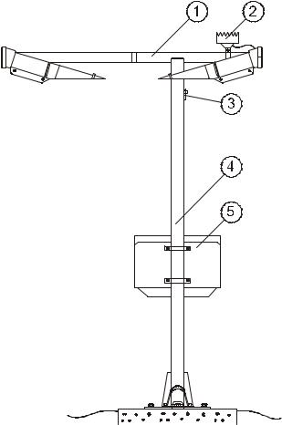
units, FDT12B Transmitter and FDR12 Receiver. The DRD12 Rain Detector is fastened to the crossarm. The electronics enclosure with the main data processing and interface units is mounted to the pole mast as seen in Figure 1 below.
0201-085
Figure 1 FD12P Weather Sensor Site
The following numbers are related to Figure 1 above:
1 = Transducer crossarm
2= DRD12 Rain Detector
3 = DTS14 Temperature Sensor
4= Pole mast
5= Electronics enclosure
The FD12P Weather Sensor consists of three parts: sensing elements, electronics enclosure, and structural elements. They are described in detail on the next page.
18______________________________________________________ M210296en-A
Chapter 2 ___________________________________________________________Product Overview
Sensing Elements
The FDT12B Transmitter emits pulses of near infrared light. It is permanently tilted 16.5º downwards. The optical power is stabilized by a closed hardware loop. The unit also includes a receiver circuit for monitoring lens contamination.
The FDR12 Receiver measures the scattered part of the FDT12B light beam. The FDR12 contains also an additional light transmitter for monitoring lens contamination. Like the transmitter, the receiver is also tilted 16.5º downwards. Therefore, the receiver unit measures light scattered at an angle of 33°.
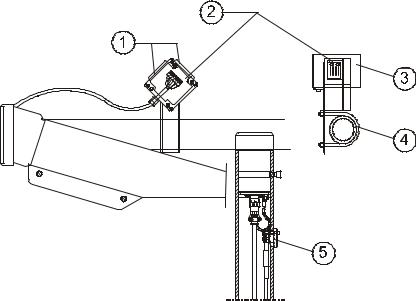
The DRD12 Rain Detector outputs a signal proportional to the amount of water on two RainCap™ sensing elements. These elements consist of thin wires protected by an insulating glass coating. The presence of water changes the capacitance of the elements. The combined capacitance of the plates is measured by the DRD12 electronics. Integrated heating resistors keep the elements dry when, for example, fog and melt snow fall on them. The Rain Detector is protected by a windshield to decrease the effect of wind on the measurement results. The DRD12 is illustrated in Figure 2 below.
The DTS14B Temperature Sensor is a Pt100 thermistor that is used to measure the crossarm temperature. See Figure 2 below.
0201-086
Figure 2 DRD12 Rain Detector and DTS14B Temperature
Sensor
VAISALA ________________________________________________________________________ 19
User's Guide _______________________________________________________________________
The following numbers refer to Figure 2 on page 19:
1 = Two RainCapTM elements
2 = DRD12 Rain Detector
3= Wind shield
4= Assembly clamp
5= DTS14 Temperature sensor
Electronics Enclosure
The FDP12 Control Unit is the main data processor and communication unit of the FD12P.
The DRI21 Interface Board is a Vaisala, general-purpose sensor interface, with several analog and digital input channels. In the FD12P, one of the DRI21 Interface Board channels is used for measuring the crossarm temperature and the DRD12 analog signal. In addition, the DRI21 controls the DRD12 heating and reads the precipitation ON/OFF status.
The FDW13 Mains Power Supply converts the mains voltage to
24 VAC power for the FDS12 regulator and the heater elements. The FDW13 includes also the mains voltage selector and the mains ON/OFF switch, which also functions as an automatic fuse.
The FDS12 DC Voltage Regulatorconverts the AC or DC input voltage (min. 18 V) to 12 VDC power used by FD12P electronics. The FDS12 also includes one relay used to control heater power.
The DMX21 Modem (optional) is a standard, 300-baud modem used only in the leased line mode with the FD12P.
The FDE12 Backup Temperature Sensor is included.
Structural Elements
The structural elements include the pole mast with a standard height of 2 meters and the FDC115 Transducer Crossarm with a length of 1.5 meters, which is also the total width of the FD12P.
20______________________________________________________ M210296en-A
Chapter 2 ___________________________________________________________Product Overview
Operating Principle
The FD12P Weather Sensor is a microprocessor controlled, intelligent sensor combining optical forward scatter measurement, capacitive precipitation sensing, and temperature measurement. The main units of the FD12P are shown in Figure 3 below.
9502-091
Figure 3 FD12P Block Diagram
The FD12P evaluates Meteorological Optical Range (MOR) by measuring the intensity of infrared light scattered at an angle of 33°. The scatter measurement is converted to the visibility value (MOR) after a careful analysis of the signal properties. Special processing is used in case of precipitation.
The FD12P software detects precipitation droplets from rapid changes in the scatter signal. The droplet data is used to estimate optical precipitation intensity and amount. In addition to the optical signal, the analog output of the DRD12 Rain Detector is used to estimate the precipitation intensity and type.
VAISALA ________________________________________________________________________ 21
User's Guide _______________________________________________________________________
The output of the DRD12 is proportional to the water amount on the capacitive sensing surfaces while the optical intensity is proportional to the total volume of the reflecting particles. The ratio of optical and capacitive intensities is used to determine the basic precipitation type.
The crossarm temperature (TS) is measured with the DTS14B Temperature Sensor connected to the DRI21 interface card. The temperature data together with the optical signal profile and the DRD12 surface sensor data are used to determine the actual weather code.
The software performs all signal analyses in the FD12P except the DRD12 Rain ON/OFF status, which is hardware-based and is used as an auxiliary parameter. The FD12P has a fixed program that is divided into tasks executed under control of a real-time operating system kernel. Each task is like an endless loop with a limited function. The operating system kernel controls the timing of the tasks and the interactions between the tasks.
Using FD12P
The FD12P is typically used as a component of a weather observing system. The final weather message (SYNOP, METAR) is then coded in the central unit of a weather observation system (for example, Vaisala MILOS 500) or by a human observer using the FD12P as an observation aid.
The FD12P output is a digital serial interface, which can be configured into two different operating modes: the sensor can be set to send a data message automatically at selected intervals, or the FD12P can be polled by the host computer. The same serial line is also used as an operator interface.
The operator controls and checks the operation of the FD12P by using a maintenance terminal. A set of built-in commands and test routines is provided for configuring and monitoring the multiple functions of the FD12P.
The standard data messages contain a status character for indicating faults detected by the internal diagnostics. If the error status is set, the operator can view a special status message. It contains detailed results of the diagnostics and a written description of the fault. Using this information, the operator can take corrective action or provide the maintenance personnel with valuable advice.
22______________________________________________________ M210296en-A
Chapter 2 ___________________________________________________________Product Overview
Equipment Nomenclature
The standard equipment nomenclature and common names are listed in Table 3 and Table 4 below.
Table 3 |
Basic Set |
|
Type |
Name |
Description |
FDC115 |
Transducer Crossarm |
Optics, analog, monitoring |
|
|
assembly |
FDT12B |
Transmitter |
|
FDR12 |
Receiver |
|
16614ZZ |
Crossarm Cable |
|
FDB12 |
Electronics Enclosure |
Power, conversions, interfacing |
|
|
assembly |
FDP12 |
Processor Board |
|
FDS12 |
DC Voltage Regulator |
|
FDW13 |
Mains Power Supply |
|
DRI21 |
Interface Board |
|
16615ZZ |
Transducer Cable |
|
16737ZZ |
I/O Bus Cable |
|
DRD12 |
Rain Detector |
|
FD30513 |
Pole Mast |
Standard 2-m mast |
13145 |
Base Plate and |
|
|
Installation Set |
|
Table 4 |
Options |
|
Type |
Name |
Description |
FDA13 |
Visibility Calibration Set |
|
FD45094 |
Maintenance cable |
RS232 cable with 9-pin D- |
|
|
connector. |
Termbox-48 |
Mains and Signal |
Adapting/extending the local |
|
Junction Box |
cable. Contains heavy-duty |
|
|
transient protection circuitry. |
FD12MODEM |
Modem Option |
For remote communication. |
FD12PLM11 |
LM11 Option |
For ambient light |
|
|
measurement. |
16616ZZ |
Extended Transducer |
For optional high-mast |
|
Cable |
mounting. |
VAISALA ________________________________________________________________________ 23
User's Guide _______________________________________________________________________
Specifications
Mechanical Specifications
-Dimensions: 2.3 m × 1.6 m × 0.6 m (H × W × D)
-Weight: 35 kg, excluding the installation plate for the pole mast
-Mounting: on a concrete foundation with three 16-mm bolts
-Material: anodized aluminum, natural gray
Electrical Specifications
-Mains supply: 115/230 VAC ± 20 %, 45 ... 65 Hz
-Maximum power consumption: 35 W + 100 W defrosting heaters (in cold weather)
The sensor electronics:
-Lock-in amplifier
-LED power stabilizer
-Contamination monitor
-Lens heater
The control unit:
-Intel 8031 microprocessor
-Program memory, 64 Kbytes
-Read/write memory, 32 Kbytes
Outputs:
-Serial data line may be used either as RS-232 level signals or interfaced via an optional data modem
-RS-485 (2-wire)
-4 - 20 mA analog current (sink) output
24______________________________________________________ M210296en-A
Chapter 2 ___________________________________________________________Product Overview
The output data:
-Automatic or polled data message
-Visibility, present weather, precipitation and status data
-Automatic message type and interval is selectable at 15 seconds to n × 15 seconds (n < 18) intervals
The analog visibility output:
-Selectable range and mode (linear or logarithmic)
-Status control bit for remote alarm relay, etc.
-Alarms and warnings (hardware failures, visibility limits)
Optical Specifications
Operating principle:
-Forward scatter at an angle of 33o and capacitive rain sensor. The light transmitter:
-Light source: near-infrared LED
-Peak wavelength: 875 nm
-Modulation frequency: 2.3 kHz
-Transmitter lens diameter: 71 mm
-Reference photodiode: for light source control
-Backscatter photodiode: for contamination and blockage measurement
The light receiver:
-Photodiode: PIN 6 DI
-Spectral response: max. responsivity at 850 nm, 0.55 A/W
(in range 550 ... 1050 nm over 0.3 A/W)
-Reception lens diameter: 71 mm
-Backscatter light source: near-infrared LED for contamination and blockage measurement
VAISALA ________________________________________________________________________ 25
User's Guide _______________________________________________________________________
Capabilities and Limitations
Visibility Measurement
Specifications
Measurement range of Meteorological Optical Range (MOR):
-10 ... 50 000 m according to a 5 % Contrast Threshold Definition
Accuracy:
-± 10 %, range 10 ... 10 000 m
-± 20 %, range 10 000 ... 50 000 m Instrument consistency:
-+ 4 %
Update interval:
- 15 seconds
Weather Sensing Specifications
Precipitation detection sensitivity:
-0.05 mm/h or less, within 10 minutes Weather type identification:
-11 different types of precipitation
-Fog (mist) and haze (smoke, sand) Weather type reporting:
-WMO code table 4680 (with some additions from code table 4677)
-Code letters for precipitation, NWS
-WMO code table 4678 (supported codes are shown in Table 34 on page 145).
26______________________________________________________ M210296en-A
Chapter 2 ___________________________________________________________Product Overview
Precipitation intensity measurement:
-Range 0.00 ... 999 mm/h
-Accuracy ± 30 % (range 0.5 ... 20 mm/h, liquid precipitation)
Environmental Specifications
Operating temperature range:
-− 40 ... +55 oC Operating humidity range:
-Up to 100 % RH Wind speed:
-Up to 60 m/s (standard mast) Sun orientation:
-Direct and reflected sunlight into the light receiver must be avoided.
VAISALA ________________________________________________________________________ 27
User's Guide _______________________________________________________________________
This page intentionally left blank.
28______________________________________________________ M210296en-A
Chapter 3 ________________________________________________________________ Installation
CHAPTER 3
INSTALLATION
|
This chapter provides you with information to help you install this |
|
product. |
|
|
NOTE |
Before installation, read section Product Related Safety Precautions |
|
on page 13. |
|
|
Organizing Installation
Before you begin to install the FD12P Weather Sensor, make a plan of the installation steps. The following is an example of how to organize the installation process.
1.Surveying the site:
-Find the most representative measurement site.
-Determine orientation of the Weather Sensor.
2.Cabling plan is required for the following:
-Grounding cabling layout and cable type.
-Power supply cabling layout and cable type.
-Modem/signal cabling layout and cable type.
3.Ordering the construction materials and cables.
4.Digging for cables and foundation.
5.Casting the concrete:
-Prepare concrete blocks by using a casting mold.
-Cast the fixing bolts in their places at the same time.
VAISALA ________________________________________________________________________ 29
User's Guide _______________________________________________________________________
6.Installing the base plate and the pole mast:
-Install the base plate with the bolts on the concrete block.
-Level the plate.
-Mount the pole mast on the base plate.
-Mount the junction box to the pole mast (optional). Junction boxes are available from Vaisala.
7.Connecting cables:
-Connect the mains and signal cables of the site to the junction box or have them ready for direct connection to the sensor.
8.Final installation:
-Install the electronics enclosure and the crossarm of the FD12P to the pole mast.
-Connect the power and signal cables of the FD12P.
-Connect the modem/signal line to the host computer, display, etc.
9.Start-up tests for the system.
Location and Orientation
The main requirements for the location of the FD12P are as follows:
1.Place the FD12P at a site where the measurements will be representative of the surrounding weather conditions.
The ideal site has a minimum clearance of 100 meters from all large buildings and other constructions that generate heat and/or obstruct precipitation droplets. Also avoid shading of trees as this may cause changes in the microclimate.
2.Make sure the site is free of obstacles and reflective surfaces, which disturb the optical measurements and act as obvious sources of contamination.
There must not be any obstacles in the line-of-sight of the transmitter and receiver units (see Figure 4 on page 31). If the transmitter beam is reflected from obstacles back to the receiver unit, the sensor will indicate too low MOR values as the reflected signal cannot be distinguished from the real scatter signal. Reflections are detected by rotating the sensor crossarm. They will change depending on the crossarm orientation. Also the visibility reading will change accordingly.
30______________________________________________________ M210296en-A
 Loading...