


 Loading...
USER'S GUIDE
Vaisala HydroMet™ Data Collection Platform
Volume 1
M210784EN-E
PUBLISHED BY |
|
|
|
Vaisala Oyj |
Phone (int.): |
+358 |
9 8949 1 |
P.O. Box 26 |
Fax: |
+358 |
9 8949 2227 |
FIN-00421 Helsinki |
|
|
|
Finland |
|
|
|
Visit our Internet pages at http://www.vaisala.com/
© Vaisala 2010
No part of this manual may be reproduced in any form or by any means, electronic or mechanical (including photocopying), nor may its contents be communicated to a third party without prior written permission of the copyright holder.
The contents are subject to change without prior notice.
Please observe that this manual does not create any legally binding obligations for Vaisala towards the customer or end user. All legally binding commitments and agreements are included exclusively in the applicable supply contract or Conditions of Sale.
________________________________________________________________________________
Table of Contents
CHAPTER 1
GENERAL INFORMATION . . . . . . . . . . . . . . . . . . . . . . . . . . . . . . . . . . . . . .9
About This Manual . . . . . . . . . . . . . . . . . . . . . . . . . . . . . . . . .9
Structure of the Data Collection Platform Documentation . 10
Contents of This Manual . . . . . . . . . . . . . . . . . . . . . . . . . . 10
Version Information . . . . . . . . . . . . . . . . . . . . . . . . . . . . . . 11
Related Manuals . . . . . . . . . . . . . . . . . . . . . . . . . . . . . . . .11
Documentation Conventions . . . . . . . . . . . . . . . . . . . . . . . 12
Product-Related Safety Precautions . . . . . . . . . . . . . . . . . .13
ESD Protection . . . . . . . . . . . . . . . . . . . . . . . . . . . . . . . . . . .14
Recycling . . . . . . . . . . . . . . . . . . . . . . . . . . . . . . . . . . . . . . . .15
Regulatory Compliances . . . . . . . . . . . . . . . . . . . . . . . . . . .15
Trademarks . . . . . . . . . . . . . . . . . . . . . . . . . . . . . . . . . . . . . .15
License Agreement . . . . . . . . . . . . . . . . . . . . . . . . . . . . . . . . 15
Redistribution License Agreement . . . . . . . . . . . . . . . . . . .16
Warranty . . . . . . . . . . . . . . . . . . . . . . . . . . . . . . . . . . . . . . . .17
CHAPTER 2
PRODUCT OVERVIEW . . . . . . . . . . . . . . . . . . . . . . . . . . . . . . . . . . . . . . .19
Data Collection Hardware . . . . . . . . . . . . . . . . . . . . . . . . . . .19
QML Logger . . . . . . . . . . . . . . . . . . . . . . . . . . . . . . . . . . . .19
QML Logger Connector Block . . . . . . . . . . . . . . . . . . . . . .22
Accessories . . . . . . . . . . . . . . . . . . . . . . . . . . . . . . . . . . . . 25
Sensor Multiplexer . . . . . . . . . . . . . . . . . . . . . . . . . . . . 25
Digital I/O Module . . . . . . . . . . . . . . . . . . . . . . . . . . . . 26
Transient Protection Devices. . . . . . . . . . . . . . . . . . . . 27
Communication Modules . . . . . . . . . . . . . . . . . . . . . . . . . .28
RS-232 Module . . . . . . . . . . . . . . . . . . . . . . . . . . . . . . 28
Isolated RS-485 Communication Module . . . . . . . . . . 28
Dual-Isolated RS-485 Communication Module . . . . . . 29
Fixed Line Modem Module. . . . . . . . . . . . . . . . . . . . . . 30
Ethernet Communication Module DSE101 . . . . . . . . . 31
Data Collection Software . . . . . . . . . . . . . . . . . . . . . . . . . . .32
Operating Software . . . . . . . . . . . . . . . . . . . . . . . . . . . . . . 32
AWS Client Software . . . . . . . . . . . . . . . . . . . . . . . . . . 32
Setup Software . . . . . . . . . . . . . . . . . . . . . . . . . . . . . . . . . 33
Lizard Setup Software . . . . . . . . . . . . . . . . . . . . . . . . . 33
Updating QML Software . . . . . . . . . . . . . . . . . . . . . . . . . . . 34
VAISALA________________________________________________________________________ 1
User’s Guide ______________________________________________________________________
CHAPTER 3
AWS CLIENT SOFTWARE . . . . . . . . . . . . . . . . . . . . . . . . . . . . . . . . . . . . .35 Product Overview . . . . . . . . . . . . . . . . . . . . . . . . . . . . . . . . .35
Installing AWS Client . . . . . . . . . . . . . . . . . . . . . . . . . . . . . .36
Minimum System Requirements . . . . . . . . . . . . . . . . . . . .36 Installation Procedure . . . . . . . . . . . . . . . . . . . . . . . . . . . .37
Establishing Terminal Connection . . . . . . . . . . . . . . . . . . .41
Using AWS Client Software . . . . . . . . . . . . . . . . . . . . . . . . .43
Starting and Exiting AWS Client . . . . . . . . . . . . . . . . . . . . .43 AWS Client Main Window . . . . . . . . . . . . . . . . . . . . . . . . .44 Defining AWS Client Settings . . . . . . . . . . . . . . . . . . . . . . .45 Read Only Mode . . . . . . . . . . . . . . . . . . . . . . . . . . . . . 45 Address Book. . . . . . . . . . . . . . . . . . . . . . . . . . . . . . . . 45 Serial Line Connections . . . . . . . . . . . . . . . . . . . . . 46 TCP/IP Socket Connections . . . . . . . . . . . . . . . . . . 48 Server Socket with SMS . . . . . . . . . . . . . . . . . . . . . 50 Dial-Up Connections . . . . . . . . . . . . . . . . . . . . . . . . 53 Options Window. . . . . . . . . . . . . . . . . . . . . . . . . . . . . . 55 Number Format . . . . . . . . . . . . . . . . . . . . . . . . . . . . . . 57 Opening Service Connection . . . . . . . . . . . . . . . . . . . . . . .57 Giving Commands . . . . . . . . . . . . . . . . . . . . . . . . . . . . . . .59 Closing Service Connection . . . . . . . . . . . . . . . . . . . . . . . .60 Managing User Levels . . . . . . . . . . . . . . . . . . . . . . . . . . . .61
Modifying Station Settings . . . . . . . . . . . . . . . . . . . . . . . . . .63
Setting the QML Logger Clock . . . . . . . . . . . . . . . . . . . . . .64 Setting Static Parameters . . . . . . . . . . . . . . . . . . . . . . . . .65 Station Parameter Backup and Restore. . . . . . . . . . . . 67 Calibrating Sensors . . . . . . . . . . . . . . . . . . . . . . . . . . . . . .69 Sensor Status List . . . . . . . . . . . . . . . . . . . . . . . . . . . . 72 Offset Calibration . . . . . . . . . . . . . . . . . . . . . . . . . . . . . 73 Manual Calibration . . . . . . . . . . . . . . . . . . . . . . . . . . . . 74 Entering Values for Manual Sensors . . . . . . . . . . . . . . . . .76 Viewing Manual Sensors in AWS Client . . . . . . . . . . . 76 Entering Values for Manual Sensors . . . . . . . . . . . . . . 78
Setup File . . . . . . . . . . . . . . . . . . . . . . . . . . . . . . . . . . . . . . . .79
Selecting Setup File . . . . . . . . . . . . . . . . . . . . . . . . . . . . . .79 Uploading Setup File . . . . . . . . . . . . . . . . . . . . . . . . . . . . .80 Secure Setup Upload . . . . . . . . . . . . . . . . . . . . . . . . . . . . .82 Downloading Setup Files from QML Logger . . . . . . . . . . .83 AWS Settings Cleanup . . . . . . . . . . . . . . . . . . . . . . . . . . . .84
Data Logging . . . . . . . . . . . . . . . . . . . . . . . . . . . . . . . . . . . . .85
Log Data Format . . . . . . . . . . . . . . . . . . . . . . . . . . . . . . . .86 Controlling Logging . . . . . . . . . . . . . . . . . . . . . . . . . . . . . .87 Measurement Enable or Disable . . . . . . . . . . . . . . . . . . . .88 Freeing Up Logging Space . . . . . . . . . . . . . . . . . . . . . . . .90 Working with Data Log Files . . . . . . . . . . . . . . . . . . . . . . .90
Downloading Log Files. . . . . . . . . . . . . . . . . . . . . . . . . 91 Converting Downloaded Log Files to CSV Format . . . 94 Auto Downloading Log Files . . . . . . . . . . . . . . . . . . . . 96 Viewing the Status of Auto Downloads . . . . . . . . . . . 101
2 ____________________________________________________________________M210784EN-E
________________________________________________________________________________
Using External Memory Card . . . . . . . . . . . . . . . . . . . . . . . 102
Automatic Erase from External Memory Card . . . . . . . . .103
Resetting the QML Logger . . . . . . . . . . . . . . . . . . . . . . . . .103
Reset Using the Reset Button . . . . . . . . . . . . . . . . . . . . .104
Sleep Command . . . . . . . . . . . . . . . . . . . . . . . . . . . . . . . . .105 Wakeup Command . . . . . . . . . . . . . . . . . . . . . . . . . . . . . . .105 Command Reference for Terminal Connection . . . . . . . .106
CHAPTER 4
TROUBLESHOOTING . . . . . . . . . . . . . . . . . . . . . . . . . . . . . . . . . . . . . . .111 Troubleshooting Procedure . . . . . . . . . . . . . . . . . . . . . . . .111 Visual Check . . . . . . . . . . . . . . . . . . . . . . . . . . . . . . . . . . . .117 Determining QML Logger Operation Mode . . . . . . . . . . . .119
Establishing Terminal Connection for Troubleshooting .119
Recording Terminal Connection Text . . . . . . . . . . . . . . .119 Opening a Service Connection through QML Logger . . . 120 Connection Problems . . . . . . . . . . . . . . . . . . . . . . . . . . . .122 Error Messages . . . . . . . . . . . . . . . . . . . . . . . . . . . . . . . . 122
Resetting QML Logger . . . . . . . . . . . . . . . . . . . . . . . . . . . .123 Determining Sensor Status . . . . . . . . . . . . . . . . . . . . . . . .124
Using External Memory Card . . . . . . . . . . . . . . . . . . . . . . .128
Automatic Erase from External Memory Card . . . . . . . . .129
Commands for Troubleshooting Purposes . . . . . . . . . . .129
LASTVAL Command . . . . . . . . . . . . . . . . . . . . . . . . . . . .130 Warnings and Errors . . . . . . . . . . . . . . . . . . . . . . . . . . . .131 System Information . . . . . . . . . . . . . . . . . . . . . . . . . . . . . 133 Battery Status . . . . . . . . . . . . . . . . . . . . . . . . . . . . . . . . . 135 Measurement Enable or Disable . . . . . . . . . . . . . . . . . . . 136
Technical Support . . . . . . . . . . . . . . . . . . . . . . . . . . . . . . . . 138
CHAPTER 5
TECHNICAL DATA . . . . . . . . . . . . . . . . . . . . . . . . . . . . . . . . . . . . . . . . . .139
Wiring Instructions . . . . . . . . . . . . . . . . . . . . . . . . . . . . . . . 139
RS-232 Module DSU232 . . . . . . . . . . . . . . . . . . . . . . . . .140
Isolated RS-485 Module DSI485 . . . . . . . . . . . . . . . . . . . 142
Dual RS-485 Module DSI486, Version A . . . . . . . . . . . . . 143
Dual RS-485 Module DSI486, Version B . . . . . . . . . . . . . 146
Digital I/O Module QMI118 . . . . . . . . . . . . . . . . . . . . . . . . 147
Fixed Line Modem DMX501 . . . . . . . . . . . . . . . . . . . . . . 148
Ethernet Communication Module DSE101 . . . . . . . . . . . .149
Specifications . . . . . . . . . . . . . . . . . . . . . . . . . . . . . . . . . . .150
QML201 Logger, Version C . . . . . . . . . . . . . . . . . . . . . . . 150
APPENDIX A
GLOSSARY . . . . . . . . . . . . . . . . . . . . . . . . . . . . . . . . . . . . . . . . . . . . . . .153
VAISALA________________________________________________________________________ 3
User’s Guide ______________________________________________________________________
4 ____________________________________________________________________M210784EN-E
________________________________________________________________________________
List of Figures
Figure 1 QML Logger . . . . . . . . . . . . . . . . . . . . . . . . . . . . . . . . . . . . . . .19 Figure 2 QML Logger without Cover . . . . . . . . . . . . . . . . . . . . . . . . . . .21 Figure 3 CompactFlash Memory Card Reader . . . . . . . . . . . . . . . . . . .22 Figure 4 Connector Blocks. . . . . . . . . . . . . . . . . . . . . . . . . . . . . . . . . . . 24 Figure 5 Sensor Multiplexer QMU101 . . . . . . . . . . . . . . . . . . . . . . . . . . 25 Figure 6 Digital I/O Module QMI118. . . . . . . . . . . . . . . . . . . . . . . . . . . . 26 Figure 7 Surge Protector for Serial Lines. . . . . . . . . . . . . . . . . . . . . . . . 27 Figure 8 RS-232 Communication Module DSU232 . . . . . . . . . . . . . . . .28 Figure 9 Isolated RS-485 Communication Module DSI485 . . . . . . . . . . 28 Figure 10 Dual-Isolated RS-485 Communication Module DSI486 . . . . . . 29 Figure 11 Fixed Line Modem Module DMX501 . . . . . . . . . . . . . . . . . . . . 30 Figure 12 Ethernet Communication Module DSE101 . . . . . . . . . . . . . . . 31 Figure 13 Installation Wizard Welcome Window . . . . . . . . . . . . . . . . . . .37 Figure 14 License Agreement Window . . . . . . . . . . . . . . . . . . . . . . . . . . 38 Figure 15 Select Installation Folder Window . . . . . . . . . . . . . . . . . . . . . .39 Figure 16 Ready to Install Window. . . . . . . . . . . . . . . . . . . . . . . . . . . . . . 39 Figure 17 Installation Complete Window . . . . . . . . . . . . . . . . . . . . . . . . . 40 Figure 18 Connecting Terminal Cable . . . . . . . . . . . . . . . . . . . . . . . . . . .41 Figure 19 Terminal Connector COM0 Pins . . . . . . . . . . . . . . . . . . . . . . . 42 Figure 20 Terminal Main Window. . . . . . . . . . . . . . . . . . . . . . . . . . . . . . .43 Figure 21 Terminal Showing Report. . . . . . . . . . . . . . . . . . . . . . . . . . . . .44 Figure 22 Address Book Window. . . . . . . . . . . . . . . . . . . . . . . . . . . . . . .46 Figure 23 Creating Serial Line Address Book Entry. . . . . . . . . . . . . . . . . 47 Figure 24 Creating TCP/IP Socket Connection Address Book Entry. . . . 49 Figure 25 Creating Server Socket with SMS Address Book Entry. . . . . . 51 Figure 26 Creating Dial-up Connection Address Book Entry . . . . . . . . . .53 Figure 27 Options Window. . . . . . . . . . . . . . . . . . . . . . . . . . . . . . . . . . . .55 Figure 28 Address Book Window. . . . . . . . . . . . . . . . . . . . . . . . . . . . . . .58 Figure 29 Common Parameters Window . . . . . . . . . . . . . . . . . . . . . . . . . 63 Figure 30 Set Logger Time Window. . . . . . . . . . . . . . . . . . . . . . . . . . . . .64 Figure 31 Static Parameters Window. . . . . . . . . . . . . . . . . . . . . . . . . . . . 66 Figure 32 Selecting File for Station Settings Backup . . . . . . . . . . . . . . . .67 Figure 33 Parameter Backup Completed. . . . . . . . . . . . . . . . . . . . . . . . . 67 Figure 34 Selecting File for Station Settings Restore. . . . . . . . . . . . . . . .68 Figure 35 Parameter Restore Complete . . . . . . . . . . . . . . . . . . . . . . . . . 68 Figure 36 Calibration Window . . . . . . . . . . . . . . . . . . . . . . . . . . . . . . . . . 70 Figure 37 Offset Calibration Window . . . . . . . . . . . . . . . . . . . . . . . . . . . . 73 Figure 38 Manual Calibration Window . . . . . . . . . . . . . . . . . . . . . . . . . . . 75 Figure 39 Manual Sensor Details. . . . . . . . . . . . . . . . . . . . . . . . . . . . . . .77 Figure 40 Entering Values for Manual Sensor . . . . . . . . . . . . . . . . . . . . .78 Figure 41 Selecting an Upload Configuration File . . . . . . . . . . . . . . . . . . 81 Figure 42 Setup Uplodad in Progress . . . . . . . . . . . . . . . . . . . . . . . . . . .81 Figure 43 Enabling Secure Setup Upload . . . . . . . . . . . . . . . . . . . . . . . .82 Figure 44 Setup File Download Progress View . . . . . . . . . . . . . . . . . . . . 84 Figure 45 Starting Logger Content Cleanup . . . . . . . . . . . . . . . . . . . . . .84
VAISALA________________________________________________________________________ 5
User’s Guide ______________________________________________________________________
Figure 46 Output of Logshow Command . . . . . . . . . . . . . . . . . . . . . . . . .86 Figure 47 Output of the Logstatus Command . . . . . . . . . . . . . . . . . . . . .88 Figure 48 List of Log Files Available for Downloading . . . . . . . . . . . . . . .91 Figure 49 Log File Download Settings Window . . . . . . . . . . . . . . . . . . . .92 Figure 50 Log File Download Progress View . . . . . . . . . . . . . . . . . . . . . .94 Figure 51 List of Log Files Available for Conversion . . . . . . . . . . . . . . . .95 Figure 52 Log File Conversion Settings . . . . . . . . . . . . . . . . . . . . . . . . . .96 Figure 53 Auto Download Settings Window . . . . . . . . . . . . . . . . . . . . . . .97 Figure 54 Auto Download in Progress . . . . . . . . . . . . . . . . . . . . . . . . . .100 Figure 55 Auto Download Status Window . . . . . . . . . . . . . . . . . . . . . . .101 Figure 56 Delayed Reset Prompt . . . . . . . . . . . . . . . . . . . . . . . . . . . . . .103 Figure 57 Reset Button on QML Logger . . . . . . . . . . . . . . . . . . . . . . . .104 Figure 58 QML Logger without Cover . . . . . . . . . . . . . . . . . . . . . . . . . .118 Figure 59 Reset Button on QML Logger . . . . . . . . . . . . . . . . . . . . . . . .123 Figure 60 Settings Menu: Calibration Window . . . . . . . . . . . . . . . . . . . .125 Figure 61 RS-232 Wiring Diagram . . . . . . . . . . . . . . . . . . . . . . . . . . . . .140 Figure 62 Suggested T-Connection in Dual Port Mode . . . . . . . . . . . . .140 Figure 63 SDI-12 Jumper of DSU232-C. . . . . . . . . . . . . . . . . . . . . . . . .141 Figure 64 Isolated RS-485 Module Wiring Diagram. . . . . . . . . . . . . . . .142 Figure 65 Dual RS-485 Module Wiring Diagram . . . . . . . . . . . . . . . . . .143 Figure 66 Dual RS-485 Module Default Jumper Locations . . . . . . . . . .144 Figure 67 Dual RS-485 Wiring Diagram for RS-485 and RS-232 . . . . .144 Figure 68 Dual RS-485 Wiring Diagram for SDI-12 and 12 VDC
Power Supply . . . . . . . . . . . . . . . . . . . . . . . . . . . . . . . . . . . . .145 Figure 69 RS-232 Jumper Settings . . . . . . . . . . . . . . . . . . . . . . . . . . . .146 Figure 70 Digital I/O Module Wiring Diagram (Digital Outputs) . . . . . . .148 Figure 71 Fixed Line Modem Wiring Diagram . . . . . . . . . . . . . . . . . . . .148 Figure 72 Ethernet Communication Module DSE101 Wiring Diagram. .149
6 ____________________________________________________________________M210784EN-E
________________________________________________________________________________
List of Tables
Table 1 Structure of the DCP Manual Set. . . . . . . . . . . . . . . . . . . . . . . . .10 Table 2 Manual Versions . . . . . . . . . . . . . . . . . . . . . . . . . . . . . . . . . . . . .11 Table 3 Related Manuals . . . . . . . . . . . . . . . . . . . . . . . . . . . . . . . . . . . . .11 Table 4 Analog Measurement Channels. . . . . . . . . . . . . . . . . . . . . . . . . . 23 Table 5 Power Channels. . . . . . . . . . . . . . . . . . . . . . . . . . . . . . . . . . . . . .23 Table 6 Minimum System Requirements . . . . . . . . . . . . . . . . . . . . . . . . . 36 Table 7 Toolbar Icons and Functions . . . . . . . . . . . . . . . . . . . . . . . . . . . . 44 Table 8 Settings in AWS Client Options Window . . . . . . . . . . . . . . . . . . . 55 Table 9 Interpreting Help Texts (the Correct Syntax) . . . . . . . . . . . . . . . .59 Table 10 Accessible Commands in Different User Levels . . . . . . . . . . . . .62 Table 11 Common Parameters Window . . . . . . . . . . . . . . . . . . . . . . . . . . . 63 Table 12 Fields in the Calibration Windows . . . . . . . . . . . . . . . . . . . . . . . .71 Table 13 Sensor Status List . . . . . . . . . . . . . . . . . . . . . . . . . . . . . . . . . . . . 72 Table 14 Fields in Manual Sensors Window. . . . . . . . . . . . . . . . . . . . . . . . 77 Table 15 Log Memory Capacity . . . . . . . . . . . . . . . . . . . . . . . . . . . . . . . . . 86 Table 16 Log Entry Status . . . . . . . . . . . . . . . . . . . . . . . . . . . . . . . . . . . . .87 Table 17 Log File Download Options . . . . . . . . . . . . . . . . . . . . . . . . . . . . .93 Table 18 Log File Conversion Options . . . . . . . . . . . . . . . . . . . . . . . . . . . . 96 Table 19 Settings in Auto Download Settings Window . . . . . . . . . . . . . . . . 98 Table 20 Fields in Auto Download Status Window . . . . . . . . . . . . . . . . . . . 101 Table 21 LED Blinking Sequences and Card Status Options . . . . . . . . . . . 102 Table 22 Command Set . . . . . . . . . . . . . . . . . . . . . . . . . . . . . . . . . . . . . . .106 Table 23 Recommended Tools for Troubleshooting. . . . . . . . . . . . . . . . . .112 Table 24 Test Commands for GSM Modems . . . . . . . . . . . . . . . . . . . . . . .116 Table 25 Determining Operation Mode by LED Flashing . . . . . . . . . . . . . . 119 Table 26 Parameters for the Open Command . . . . . . . . . . . . . . . . . . . . . . 121 Table 27 Some Common Connection Problems and Their Remedies . . . .122 Table 28 Error Messages . . . . . . . . . . . . . . . . . . . . . . . . . . . . . . . . . . . . . . 122 Table 29 Columns in the Sensor Calibration Tab . . . . . . . . . . . . . . . . . . . .126 Table 30 Sensor Status List . . . . . . . . . . . . . . . . . . . . . . . . . . . . . . . . . . . . 127 Table 31 LED Blinking Sequences and Card Status Options . . . . . . . . . . . 128 Table 32 DSU232-C Jumper Settings. . . . . . . . . . . . . . . . . . . . . . . . . . . . . 141 Table 33 Jumper Settings for Channel B in the RS-485 Mode . . . . . . . . . .143 Table 34 Jumper Settings for Channel B in the RS-232 Mode . . . . . . . . . .144 Table 35 Jumper Settings for DSI486-B . . . . . . . . . . . . . . . . . . . . . . . . . . . 146 Table 36 Technical Data QMI108/118 . . . . . . . . . . . . . . . . . . . . . . . . . . . . 147 Table 37 Ethernet Communication Module DSE101 Specifications . . . . . . 149 Table 38 QML201C Logger General Specifications . . . . . . . . . . . . . . . . . .150 Table 39 QML201C Logger Accuracy Specifications . . . . . . . . . . . . . . . . . 151 Table 40 QML201C Logger Regulatory Compliances . . . . . . . . . . . . . . . .152
VAISALA________________________________________________________________________ 7
User’s Guide ______________________________________________________________________
8 ____________________________________________________________________M210784EN-E
Chapter 1 ________________________________________________________ General Information
CHAPTER 1
GENERAL INFORMATION
This chapter provides general notes for the product(s) and this manual.
About This Manual
This manual provides information on the basic data collection hardware and software, namely, the QML logger and its accessories, and the software applications that are used for operating the QML logger and viewing the logged data.
This manual is applicable for data logger QML201C and AWS Client software version 7.00.
For more detailed and advanced information on data collection software and telemetry, refer to the supplementary user manuals Vaisala HydroMet™ Data Collection Platform User’s Guide, Volumes 2 and 3.
VAISALA________________________________________________________________________ 9
User's Guide ______________________________________________________________________
Structure of the Data Collection
Platform Documentation
The information in the Vaisala HydroMet™ Data Collection Platform manual set is divided between the different manuals in the documentation set as outlined in Table 1 on page 10.
Table 1 Structure of the DCP Manual Set
Manual |
Code |
Content |
User’s Guide, Volume 1 |
M210784EN |
Overview of the data collection |
|
|
platform, the QML logger, and |
|
|
related accessories. Operating |
|
|
instructions for AWS Client |
|
|
software. |
User’s Guide, Volume 2 |
M210785EN |
Operating instructions for Lizard |
|
|
Setup Software. |
User’s Guide, Volume 3 |
M210933EN |
Telemetry and sensor configuration |
|
|
in Lizard Setup Software. |
Installation Manual |
M210786EN |
Installation information on the Data |
(Field Equipment) |
|
Collection Platform with |
|
|
meteorological and/or hydrological |
|
|
sensors. |
Contents of This Manual
This manual consists of the following chapters:
-Chapter 1, General Information: This chapter provides general notes for the product(s) and this manual.
-Chapter 2, Product Overview: This chapter introduces the basic data collection hardware and software.
-Chapter 3, AWS Client Software: This chapter provides information on using Vaisala HydroMet™ Automatic Weather Station Client, or AWS Client for short, for working with the QML logger.
-Chapter 4, Troubleshooting: This chapter contains information on some common problems, their probable causes and remedies.
-Chapter 5, Technical Data: This chapter provides the technical data of the QML logger and accessory modules.
10 ___________________________________________________________________M210784EN-E
Chapter 1 ________________________________________________________ General Information
-Appendix A, Glossary: This appendix contains a glossary with explanations of some general meteorological and technical terms and terms used in specifications.
Version Information
Table 2 |
Manual Versions |
|
|
|
|
Manual Code |
|
Description |
|
|
|
M210784EN-E |
|
This manual. For MAWS system release 8.00, |
|
|
AWS Client 7.00, and data logger QML201C. |
M210784EN-D |
|
Previous version. For MAWS system release |
|
|
7.00, AWS Client 7.00, and data logger |
|
|
QML201B. |
M210784EN-C |
|
Previous version. |
M210784EN-B |
|
Previous version. |
M210784EN-A |
|
First version of this manual. |
Related Manuals
Table 3 |
Related Manuals |
|
|
|
|
Manual Code |
|
Manual Name |
M210785EN |
|
Vaisala HydroMet™ Data Collection Platform |
|
|
User's Guide, Volume 2 |
M210933EN |
|
Vaisala HydroMet™ Data Collection Platform |
|
|
User's Guide, Volume 3 |
M210786EN |
|
Vaisala HydroMet™ Data Collection Platform |
|
|
Installation Manual |
M210629EN |
|
Automatic Weather Station MAWS101 User's |
|
|
Guide |
M210630EN |
|
Automatic Weather Station MAWS201 User's |
|
|
Guide |
M210681EN |
|
Real-time Display Software YourVIEW 2000 |
|
|
YVU2000 User’s Guide |
M210743EN |
|
Voice Option for MAWS Technical Reference |
M211022EN |
|
Configuring BUFR Reports MAWS Technical Note |
VAISALA_______________________________________________________________________ 11
User's Guide ______________________________________________________________________
|
|
|
Documentation Conventions |
|
|
|
|
Throughout this manual, important safety considerations are |
|
|
|
|
highlighted as follows: |
|
|
|
|
|
|
|
|
WARNING |
Warning alerts you to a serious hazard. If you do not read and follow |
|
|
|
|
instructions very carefully at this point, there is a risk of injury or even |
|
|
|
|
death. |
|
|
|
|
|
|
|
|
|
|
|
|
|
|
|
|
|
|
CAUTION |
Caution warns you of a potential hazard. If you do not read and follow |
|
|
|
|
instructions carefully at this point, the product could be damaged or |
|
|
|
|
important data could be lost. |
|
|
|
|
|
|
|
|
|
|
|
|
|
NOTE |
Note highlights important information on using the product. |
|
|
|
|
|
|
12 ___________________________________________________________________M210784EN-E
Chapter 1 ________________________________________________________ General Information
Product-Related Safety Precautions
|
|
The product has been tested for safety and approved as shipped from the |
|
|
|
factory. The following safety precautions are not related to any specific |
|
|
|
procedures and therefore do not appear elsewhere in this manual. They |
|
|
|
are recommended precautions that personnel must understand and |
|
|
|
apply during different phases of operation and maintenance. |
|
|
|
|
|
|
WARNING |
Keep away from live circuits. Operating personnel must observe safety |
|
|
|
regulations at all times. Component replacement or internal |
|
|
|
adjustments must be made by qualified maintenance personnel. Do not |
|
|
|
replace components with the power cable connected. Under certain |
|
|
|
conditions, dangerous voltages may exist for some time even with the |
|
|
|
power cable disconnected. To avoid injuries, disconnect power and |
|
|
|
discharge circuits before touching them. |
|
|
|
|
|
|
|
|
|
|
|
|
|
|
WARNING |
Do not service alone. Under no circumstances should any person reach |
|
|
|
into parts and assemblies that are mains powered and alive, for the |
|
|
|
purpose of servicing, except in the presence of someone who is |
|
|
|
capable of rendering aid. |
|
|
|
|
|
|
|
|
|
|
|
|
|
|
WARNING |
Personnel working with or near high voltages should be familiar with |
|
|
|
modern methods of resuscitation. |
|
|
|
|
|
|
|
|
|
|
|
|
|
|
WARNING |
Do not service a live system outdoors. Do not open units outdoors |
|
|
|
when the enclosure used contains line voltage levels. |
|
|
|
|
|
|
|
|
|
|
|
|
|
|
WARNING |
Do not operate in an explosive atmosphere, for example, when |
|
|
|
flammable gases or fumes are present. Operation of any electrical |
|
|
|
instrument in such an environment constitutes a definite safety hazard. |
|
|
|
|
|
|
|
|
|
|
|
|
|
|
WARNING |
Do not substitute parts or modify the instrument. Because of the |
|
|
|
danger of introducing additional hazards, do not install unsuitable |
|
|
|
parts in the instrument. Contact Vaisala or its authorized representative |
|
|
|
for repairs to ensure that safety features are maintained. |
|
|
|
|
|
|
|
|
|
VAISALA_______________________________________________________________________ 13
User's Guide ______________________________________________________________________
|
|
|
|
|
|
WARNING |
Use only batteries of the same type as originally installed on the |
|
|
|
system. |
|
|
|
|
|
|
|
|
|
|
|
|
|
|
CAUTION |
Do not make changes to the wiring. Incorrect wiring can damage the |
|
|
|
device and prevent it from operating correctly. |
|
|
|
|
|
|
|
|
|
|
CAUTION |
Risk of damage to the equipment if the battery is replaced with an |
|
|
|
incorrect type. |
|
|
|
|
ESD Protection
Electrostatic Discharge (ESD) can cause immediate or latent damage to electronic circuits. Vaisala products are adequately protected against ESD for their intended use. However, it is possible to damage the product by delivering electrostatic discharges when touching, removing, or inserting any objects inside the equipment housing.
To make sure you are not delivering high static voltages yourself:
-Handle ESD sensitive components on a properly grounded and protected ESD workbench. When this is not possible, ground yourself with a wrist strap and a resistive connection cord to the equipment chassis before touching the boards. When neither of the above is possible, at least touch a conductive part of the equipment chassis with your other hand before touching the boards.
-Always hold the boards by the edges and avoid touching the component contacts.
14 ___________________________________________________________________M210784EN-E

Chapter 1 ________________________________________________________ General Information
Recycling
Recycle all applicable material.
Dispose of batteries and the unit according to statutory regulations.
Do not dispose of with regular household refuse.
Regulatory Compliances
The Vaisala HydroMet™ Data Collection Platform complies with the following EU directives:
-Low Voltage Directive (2006/95/EC)
-EMC-Directive (2004/108/EC)
Trademarks
Vaisala HydroMet™ Data Collection Platform is a trademark of
Vaisala Oyj.
Windows® is a registered trademark of Microsoft Corporation in the
United States and/or other countries.
License Agreement
All rights to any software are held by Vaisala or third parties. The customer is allowed to use the software only to the extent that is provided by the applicable supply contract or Software License Agreement.
VAISALA_______________________________________________________________________ 15
User's Guide ______________________________________________________________________
Redistribution License Agreement
The QML logger software uses the TCP/IP stack produced by the "lwIP Lightweight TCP/IP stack" -project with the following copyright and license:
Copyright © 2001, 2002 Swedish Institute of Computer Science. All rights reserved.
Redistribution and use in source and binary forms, with or without modification, are permitted provided that the following conditions are met:
1.Redistributions of source code must retain the above copyright notice, this list of conditions and the following disclaimer.
2.Redistributions in binary form must reproduce the above copyright notice, this list of conditions and the following disclaimer in the documentation and/or other materials provided with the distribution.
3.The name of the author may not be used to endorse or promote products derived from this software without specific prior written permission.
THIS SOFTWARE IS PROVIDED BY THE AUTHOR "AS IS" AND ANY EXPRESS OR IMPLIED WARRANTIES, INCLUDING, BUT NOT LIMITED TO, THE IMPLIED WARRANTIES OF MERCHANTABILITY AND FITNESS FOR A PARTICULAR PURPOSE ARE DISCLAIMED. IN NO EVENT SHALL THE AUTHOR BE LIABLE FOR ANY DIRECT, INDIRECT, INCIDENTAL, SPECIAL, EXEMPLARY, OR CONSEQUENTIAL DAMAGES (INCLUDING, BUT NOT LIMITED TO, PROCUREMENT OF SUBSTITUTE GOODS OR SERVICES; LOSS OF USE, DATA, OR PROFITS; OR BUSINESS INTERRUPTION) HOWEVER CAUSED AND ON ANY THEORY OF LIABILITY, WHETHER IN CONTRACT, STRICT LIABILITY, OR TORT (INCLUDING NEGLIGENCE OR OTHERWISE) ARISING IN ANY WAY OUT OF THE USE OF THIS SOFTWARE, EVEN IF ADVISED OF THE POSSIBILITY OF SUCH DAMAGE.
16 ___________________________________________________________________M210784EN-E
Chapter 1 ________________________________________________________ General Information
Warranty
For certain products Vaisala normally gives a limited one-year warranty. Please observe that any such warranty may not be valid in case of damage due to normal wear and tear, exceptional operating conditions, negligent handling or installation, or unauthorized modifications. Please see the applicable supply contract or Conditions of Sale for details of the warranty for each product.
VAISALA_______________________________________________________________________ 17
User's Guide ______________________________________________________________________
18 ___________________________________________________________________M210784EN-E
Chapter 2 __________________________________________________________ Product Overview
CHAPTER 2
PRODUCT OVERVIEW
This chapter introduces the basic data collection hardware and software.
Data Collection Hardware
QML Logger
Figure 1 QML Logger
VAISALA_______________________________________________________________________ 19
User's Guide ______________________________________________________________________
The QML logger is a complete AWS data logger designed on one printed board only. This board contains a 32-bit Motorola CPU for data processing and 10 differential (20 single-ended) analog sensor inputs (these can also be used as digital inputs). Moreover, there are two frequency sensor interfaces, a 24-bit A/D converter, 3.3 MB of secure Flash memory for data logging, as well as an excitation power supply for sensors and a charger for the internal backup battery. The last item mentioned is not needed in systems where a backup battery with higher capacity is used.
The board uses the latest SMD (Surface Mount Device) technology and is conformal-coated for improved protection also in high humidity. Each sensor input has a varistor (VDR) protection against induced transients. The serial line connections, that is, RS-232 labeled as COM0 and RS-485 labeled as COM1, have two level ESD protection circuits with VDRs directly at input pins.
The cover of the logger can be removed for installing the battery and for resetting the weather station. In Figure 2 on page 21, the logger is shown without the cover and the optional communication modules.
20 ___________________________________________________________________M210784EN-E

Chapter 2 __________________________________________________________ Product Overview
Figure 2 QML Logger without Cover
The following numbers refer to Figure 2 on page 21:
1= Pressure sensor connector
2= Communication module places MOD1 and MOD2
3= SPI connector
4= Status LED (green)
5= Lithium battery for RTC
6= Reset button
7= CF Card connector
VAISALA_______________________________________________________________________ 21

User's Guide ______________________________________________________________________
When long signal cables are needed, these will be equipped with optional surge voltage protection devices. These surge protectors consist of a combination of VDRs, gas-filled discharge tubes, transzorb diodes, and coils, thus providing excellent protection. These DIN-rail mountable devices are easy to change without any special tools.
The QML logger is equipped with a CF card slot for logging a large amount of data. The data is logged into daily files making it easy to locate any particular data set for further analysis. The QML logger supports CF cards of up to 2 GB. These cards can be read directly in the PC. Several different types of readers are commercially available: internal PCMCIA reader as well as external readers to be connected to USB or parallel port of a PC. You are recommended to only use cards purchased from Vaisala that have been tested to function in harsh environments.
Figure 3 CompactFlash Memory Card Reader
Optional modules include, for example, various communication modules and a built-in pressure transducer.
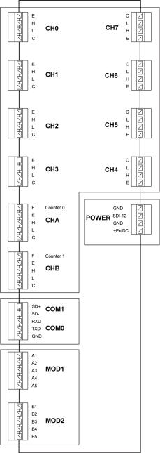
QML Logger Connector Block
The QML logger includes:
1.Ten measurement channels and one internal channel for pressure measurement.
2.One connector block for power supplies.
22 ___________________________________________________________________M210784EN-E
Chapter 2 __________________________________________________________ Product Overview
3.One connector block for communication channels.
4.Two blocks for optional communication modules.
Single-ended (H-C or L-C) or differential (H-L) measurements can be performed in the 10 measurement channels.
NOTE |
Each sensor in a basic setup has its own dedicated channel. Table 4 on |
|||
|
page 23 is to be used for reference purposes only. |
|||
|
|
|
|
|
|
Table 4 |
Analog Measurement Channels |
||
|
|
|
|
|
|
Channels |
|
Pin Name |
Description |
|
|
|
|
|
|
CH0, CH1, CH2, |
E |
12 V/25 mA voltage excitation ON/OFF, |
|
|
CH3 24-bit ADC |
|
voltage can be measured. |
|
|
|
|
|
OR: 100 A/1mA current excitation. |
|
|
|
H |
Analog input (High) |
|
|
|
L |
Analog input (Low) |
|
|
|
C |
The pin has been connected to ground |
|
|
|
|
(GND) via a 10 resistor so that the |
|
|
|
|
current can be measured. |
|
CH4, CH5, CH6, |
E |
100 A/1 mA current excitation |
|
|
CH7 24-bit ADC |
|
|
|
|
H |
Analog input (High) |
||
|
|
|
L |
Analog input (Low) |
|
|
|
C |
Common return and reference level for |
|
|
|
|
voltage measurements via the channel's |
|
|
|
|
own E-, H-, and L-pins. The pin has been |
|
|
|
|
connected directly to ground. |
|
CHA, CHB Suitable |
F |
Frequency input |
|
|
for fast-changing |
|
|
|
|
E |
0 ... 12 V/20 mA adjustable excitation |
||
|
input signals 12-bit |
|
voltage, can be measured. |
|
|
ADC |
|
|
|
|
|
H |
Fast analog input (High) |
|
|
|
|
||
|
|
|
L |
Fast analog input (Low) |
|
|
|
C |
Common return (Analog ground) |
|
Table 5 |
Power Channels |
||
|
|
|
|
|
|
Pin Name |
|
|
Description |
|
GND |
|
|
Ground |
|
SDI-12 |
|
|
SDI-12 |
|
GND |
|
|
Ground |
|
+ExtDC |
|
|
8 ... 30 VDC |
VAISALA_______________________________________________________________________ 23
User's Guide ______________________________________________________________________
Figure 4 Connector Blocks
24 ___________________________________________________________________M210784EN-E

Chapter 2 __________________________________________________________ Product Overview
Accessories
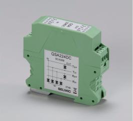
Sensor Multiplexer
|
Figure 5 |
Sensor Multiplexer QMU101 |
|
The QML logger provides the possibility to extend the measuring |
|
|
capacity with the optional QMU sensor multiplexer. It is designed to |
|
|
increase the number of analog measurement channels with eight 16-bit |
|
|
analog channels and two 12-bit analog channels. The unit increases the |
|
|
measuring capacity with ten differential measurements or alternatively |
|
|
with 20 single-ended measurements. |
|
|
The unit interfaces to the logger via the RS-485 line, and is also located |
|
|
inside the enclosure. The unit conforms to the same environmental |
|
|
immunity and emission standards as the logger. |
|
|
|
|
NOTE |
The multiplexer unit makes only analog measurements. |
|
|
|
|
|
|
|
NOTE |
The multiplexer unit can only be connected to the QML201 logger or |
|
|
newer. The type of the logger can be checked with the VER command. |
|
|
|
|
VAISALA_______________________________________________________________________ 25
User's Guide ______________________________________________________________________
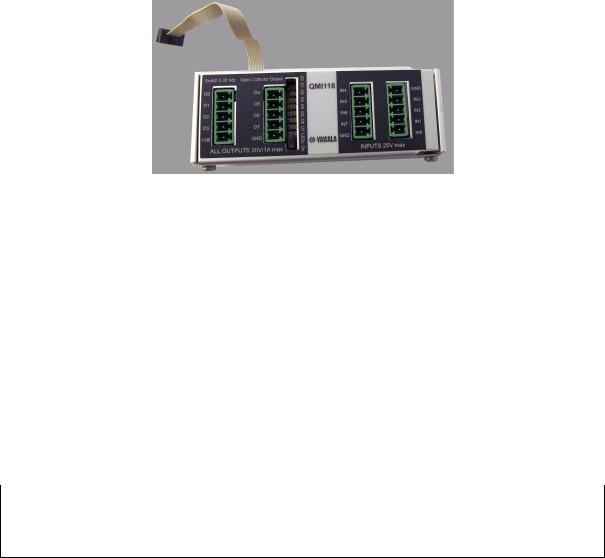
Digital I/O Module
|
Figure 6 |
Digital I/O Module QMI118 |
|
The QML logger provides the possibility to extend the I/O capacity with |
|
|
the optional digital I/O module (QMI) equipped with eight inputs and |
|
|
eight outputs. The digital I/O module interfaces to the logger via the SPI |
|
|
connector. The module is located inside the enclosure beside the logger |
|
|
and it conforms to the same environmental immunity and emission |
|
|
standards as the logger. |
|
|
The module has eight open collector outputs with 30 VDC/1 A |
|
|
continuous drive capability and LED indicators. The eight inputs of the |
|
|
module tolerate voltages from 0 to 25 VDC (the absolute maximum |
|
|
30 VDC) and they have 40 ms (typical) contact debouncing circuitry. |
|
|
The module allows connection of slow pulse inputs, for example, with |
|
|
tipping bucket rain gauges. |
|
|
|
|
NOTE |
The digital I/O module can only be connected to the QML201 logger |
|
|
or newer. The type of the logger can be checked with the VER |
|
command.
26 ___________________________________________________________________M210784EN-E
Chapter 2 __________________________________________________________ Product Overview
Transient Protection Devices
Each sensor input in the logger has a varistor (VDR) protection against induced transients. The maintenance terminal I/O ports have transzorb diodes in their inputs.
In case of long signal cables, additional transient protectors can be installed on the DIN rail. These surge protectors consist of a combination of VDR, transzorb diodes, and coils, thus providing excellent protection. These are easy to change in the field without tools.
Figure 7 Surge Protector for Serial Lines
Optional coaxial surge protectors can be used for UHF and VHF antennas as well as for the RF signal input when radio or satellite equipment is used.
VAISALA_______________________________________________________________________ 27
User's Guide ______________________________________________________________________
Communication Modules
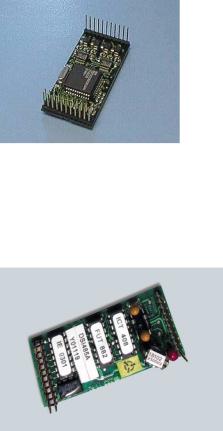
RS-232 Module
The RS-232 communication module is unisolated, providing either a double serial channel without handshaking (dual RS-232 module) or a single RS-232 with handshaking (single RS-232 module). The power consumption is less than 15 mA when communicating, less than 5 mA at standby.
The later version of the module (DSU232C) adds a separate SDI-12 interface that can be taken into use by jumper selection. Wiring for the SDI-12 is similar to the dual RS-485 module described in section DualIsolated RS-485 Communication Module on page 29.
In other aspects, the later version is compatible with the old one and can thus be used as a spare part without modifications to the system.
Figure 8 RS-232 Communication Module DSU232
Isolated RS-485 Communication Module
Figure 9 Isolated RS-485 Communication Module DSI485
28 ___________________________________________________________________M210784EN-E
Loading...