


D9V1
Table of contents
 Loading...
Ar
cher D9
AC19 00 Wi reles s Dual Band Gi gab it ADSL2+ M odem
Ro
uter
R
ev: 1.0.0
1910011060

CO
PYRIGHT & TRADEMARKS
S
pecifications are subject to change without notice.
i
s a registered trademark of
TP-LINK TECHNOLOGIES CO., LTD. Other brands and product names are trademarks or
registered tradem arks of thei r respectiv e holders.
No part of the specifications may be reproduced in any form or by any means or used to make any
derivative such as translation, transformation, or adaptation without permission from TP-LINK
TECHNOLOGIES CO., LTD. Copyright © 2014 TP-LINK TECHNOLOGIES CO., LTD. All rig hts
reserved.
http://www.tp-link.com

F
CC STATE MENT
T
his equipment has been tested and found to comply with the limits for a Class B digital device,
pursuant to part 15 of the FCC Rules. These limits are designed to provide reasonable protection
against harmful interference in a residential installation. This equipment generates, uses and can
radiate radio frequency energy and, if not installed and used in accordance with the instructions,
may cause harmful interference to radio communications. However, there is no guarantee that
interference will not occur in a particular installation. If this equipment does cause harmful
interference to radio or television reception, which can be determined by turning the equipment off
and on, the user is encouraged to try to correct the interference by one or more of the following
measures:
• Reorient or reloc ate the receivi ng antenna.
• I ncrease the separation betw een the equi pm ent and receiv er.
• Connect the equipment into an outlet on a circuit different from that to which the receiver
is connected.
• Consult the dealer or an experienced radio/ TV techni cian for help.
This device complies with part 15 of the FCC Rules. Operation is subject to the following two
conditions:
1) This devic e may not cause harmful interference.
2) This device must accept any interference received, including interference that may cause
undesired operation.
Any changes or modifications not expressly approved by the party responsible for compliance
could voi d the user’s authority to operate the equi pm ent.
Note: The manufacturer is not responsible for any radio or TV interference caused by
unauthorized modifications to this equipment. Such modifications could void the user’s authority to
operate the equipm ent.
FC
C RF Radiation Exposure Statement
T
his equipment complies with FCC RF radiation exposure limits set forth for an uncontrolled
environment. This device and its antenna must not be co-located or operating in conjunction with
any other antenna or transm itter.
“To comply with FCC RF exposure compliance requirements, this grant is applicable to only
Mobile Configurations. The antennas used for this transmitter must be installed to provide a
separation distance of at least 20 cm from all persons and must not be co-located or operating in
conjuncti on w i th any other antenna or transmit ter.”
CE
Ma rk Wa rning
at
ion distance of at least 22 cm from all persons and must not be co
conjuncti on w i th any other antenna or transmit ter. This device is indoor used only.
This device is indoor used only.

This is a class B product. In a domestic environment, this product may cause radio interference, in
w hic h case the user may be required to take adequate m eas ures.
National Restrict ions
This device is intended for home and office use in all EU countries (and other countries following
the EU directi ve 1999/5/E C) w i thout any lim itati on except for the countries m enti oned below :
Country Restriction Reason/remark
Bulgaria None
Gener al aut hor izat ion required for outdoor use and
public serv ice
France
Outdoor use limited to 10
mW e.i.r.p. within the band
2454-2483.5 M Hz
Military Radiolocation use. Refarm
ing of the 2.4 GHz
band has been ongoing in recent years to allow current
relaxed regulation. Full implement ation planned 2012
Italy None
If used out si de of own pre m ises, general aut hor ization is
required
Luxembourg None
General authorization required fo
r network and service
supply( not f or spectrum)
Norway Implemented
This s ubsection do es not apply for the geograph ic al area
within a radius of 20 k m from the centre of Ny-Ålesund
Russian Federat ion None Only for indoor applicat ions
Note: Please don’t use the product outdoors in France.
Canadian Compliance Statement
This device complies with Industry Canada license-exempt RSS standard(s). Operation is subject
to the following two conditions:
(1)This device m ay not cause interference, and
(2)This device must accept any interference, including interference that may cause undesired
operation of the devi ce.
Cet appareil est conforme aux norms CNR exemptes de licence d’Industrie Canada. Le
fonctionnem ent es t soum is aux deux conditions sui vantes:
(1)cet appareil ne doit pas provoquer d’interférences et
(2)cet appareil doit accepter toute interférence, y compris celles susceptibles de provoquer un
fonctionnem ent non s ouhaité de l’ appareil.
This device has been designed to operate with the antennas listed below, and having a maximum
gain of 5 dBi. Antennas not included in this list or having a gain greater than 5 dBi are strictly
prohibited for use with this device. The required antenna i mpedanc e is 50 ohms.
To reduce potential radio interference to other users, the antenna type and its gain should be so
chosen that the equivalent isotropically radiated power (e.i.r.p.) is not more than that permitted for
success ful com m uni cation.

Industry Canada Stat ement
Com pli es wit h the Canadian I CE S-003 Class B specifications.
Cet appareil numéri que de la classe B est conform e à la norme NM B -003 du Canada.
This device complies with RSS 210 of Industry Canada. This Class B device meets all the
requirem ents of the Canadian interference-causi ng equipm ent regulati ons.
Cet appareil numérique de la Classe B respecte toutes les exigences du Règlement sur le
mat ériel brouilleur du Canada.
Korea Warning St at ements:
당해 무선설비는 운용중 전파혼신 가능성이 있음.
NCC Not ice& BSM I Notice :
注意!
依據 低功率電波輻射性電機管理辦法
第十二條 經型式認證合格之低功率射頻電機,非經許可,公司、商號或使用者均不得擅自變更頻率、
加大功率或變更原設計之特性或功能。
第十四條 低功率射頻電機之使用不得影響飛航安全及干擾合法通行;經發現有干擾現象時,應立即
停用,並改善至無干擾時方得繼續使用。前項合法通信,指依電信規定作業之無線電信。低功率射
頻電機需忍受合法通信或工業、科學以及醫療用電波輻射性電機設備之干擾。
減少電磁波影響,請妥適使用。
安全諮詢及注意事項
●請使用原裝電源供應器或只能按照本產品注明的電源類型使用本產品。
●清潔本產品之前請先拔掉電源線。請勿使用液體、噴霧清潔劑或濕布進行清潔。
●注意防潮,請勿將水或其他液體潑灑到本產品上。
●插槽與開口供通風使用,以確保本產品的操作可靠並防止過熱,請勿堵塞或覆蓋開口。
●請勿將本產品置放於靠近熱源的地方。除非有正常的通風,否則不可放在密閉位置中。
●請不要私自打開機殼,不要嘗試自行維修本產品,請由授權的專業人士進行此項工作。
Продукт сертифіковано згідно с правилами системи УкрСЕПРО на відповідність вимогам
нормативних документів та вимогам, що передбачені чинними законодавчими актами
України.

Safety Information
When product has power button, the power button is one of the way to shut off the product;
when there is no power button, the only way to completely shut off power is to disconnect the
product or the pow er adapter from the power source.
Don’t disassemble the product, or make repairs yourself. You run the risk of electric shock
and voiding the lim it ed w arranty. If you need service, please c ontact us.
Avoid water and wet locations.
This product can be used in the follow ing countries:
AT BG BY CA CZ DE DK EE
ES FI FR GB GR HU IE IT
LT LV MT NL NO PL PT RO
RU SE SK TR UA US

TP-LINK TECHNOLOGIES CO., LTD
DECLARATION OF CONFORMITY
For the following equipm ent:
Product D escripti on: AC1900 Wireless Dual Band Gigabit ADSL2+ Modem Router
Model No.: Arche r D9
Trademark: TP-LINK
We declare under our own responsibility that the above products satisfy all the technical
regulations appl icabl e to the product within the scope of Council Direc tives:
Directives 1999/5/EC, Directives 2004/108/EC, Directives 2006/95/EC, Directives 1999/519/EC,
Directi ves 201 1/65/ EU
The above product is in conformity with the following standards or other normative documents
EN 300 328 V1.8.1: 2012
EN 301 489-1 V1.9.2:2011& EN 301 489-17 V2.2.1:2012
EN 55022:2010
EN 55024:2010
EN 61000-3-2:2006+A1:2009+A2:2009
EN 61000-3-3:2008
EN 60950-1:2006+A11: 2009+A1:2010+A12:2011
EN 50385:2002
EN 301 893 v1.7.1: 2012
The product carries the CE Mark:
Person responsibl e for m aking this declaration:
Yang Hongliang
Product M anager of International B usines s
Date of issue: 2014
TP-LINK TECHNOLO GIES CO ., LTD
Building 24 (floors 1, 3, 4, 5), and 28 (floors 1-4) Central Science and Technology Park,
Shennan Rd, Nanshan, Shenzhen, China

CONTENTS
Package Contents ................................................................................................................ 1
Chapter 1. Product Over vi ew ............................................................................................ 2
1.1 Overview of the Modem Router ........................................................................................2
1.2 Main Features....................................................................................................................3
1.3 Panel Layout......................................................................................................................4
1.3.1 The Fr ont Panel ...........................................................................................................4
1.3.2 The Bac k Panel ...........................................................................................................6
Chapter 2. Connecting the M ode m Route r .................................................................... 8
2.1 System Requirement s .......................................................................................................8
2.2 Installation Environment Requirements ............................................................................8
2.3 Connecting the Modem Router .........................................................................................8
Chapter 3. Quick Installation Guide............................................................................... 10
3.1 TCP/IP Configuration ......................................................................................................10
3.2 Quick Installation Guide ..................................................................................................11
Chapter 4. Confi gur ing the M ode m Route r ................................................................. 15
4.1 Login ................................................................................................................................15
4.2 Status...............................................................................................................................16
4.3 Quick Setup .....................................................................................................................18
4.4 O peration Mode ...............................................................................................................18
4.5 Network............................................................................................................................18
4.5.1 WA N S et tings ............................................................................................................ 19
4.5.2 Interfac e Grouping ..................................................................................................... 28
4.5.3 LAN Set tings ............................................................................................................. 29
4.5.4 IPv6 LA N S et tings ...................................................................................................... 30
4.5.5 MAC Clone ................................................................................................................ 32
4.5.6 ALG Sett ings ............................................................................................................. 32
4.5.7 DSL Set tings ............................................................................................................. 33
4.5.8 IPSec VPN ................................................................................................................ 33
4.6 IPTV .................................................................................................................................36
4.7 DHCP Serv er ...................................................................................................................37
4.7.1 DHCP S ett ings .......................................................................................................... 37

4.7.2 Clients List ................................................................................................................. 39
4.7.3 Addr ess Res ervat ion .................................................................................................. 39
4.7.4 Conditional Pool......................................................................................................... 40
4.8 Wireless 2.4GHz..............................................................................................................42
4.8.1 Basi c S et tings............................................................................................................ 42
4.8.2 WP S Set t i ngs ............................................................................................................ 44
4.8.3 Wirel ess S ecurity ....................................................................................................... 46
4.8.4 Wirel ess S chedule ..................................................................................................... 48
4.8.5 Wireless MA C Filtering ............................................................................................... 49
4.8.6 Wirel ess A dvanc ed .................................................................................................... 50
4.8.7 Wirel ess S tat us.......................................................................................................... 52
4.9 Wireless 5GHz.................................................................................................................52
4.9.1 Basi c S et tings............................................................................................................ 52
4.9.2 WP S Set t i ngs ............................................................................................................ 54
4.9.3 Wirel ess S ecurity ....................................................................................................... 56
4.9.4 Wirel ess S chedule ..................................................................................................... 58
4.9.5 Wireless MA C Filtering ............................................................................................... 59
4.9.6 Wirel ess A dvanc ed .................................................................................................... 61
4.9.7 Wirel ess S tat us.......................................................................................................... 62
4.10 Guest Network .................................................................................................................63
4.10.1 Basic Sett i ngs 2.4GHz .............................................................................................. 63
4.10.2 Basic Sett i ngs 5G Hz ................................................................................................. 64
4.10.3 Guest S t atus 2.4GHz ................................................................................................ 66
4.10.4 Guest S t atus 5GHz ................................................................................................... 66
4.11 USB Settings ...................................................................................................................67
4.11.1 USB Mass S torage ................................................................................................... 67
4.11.2 User A cc ount s .......................................................................................................... 68
4.11.3 St orage S hari ng........................................................................................................ 68
4.11.4 FTP Server............................................................................................................... 70
4.11.5 Media Se rver ............................................................................................................ 72
4.11.6 Print S erver .............................................................................................................. 73
4.12 Route Settings .................................................................................................................73
4.12.1 Default Gat eway ....................................................................................................... 74
4.12.2 St atic Route ............................................................................................................. 74
4.12.3 RIP Set tings ............................................................................................................. 75
4.13 IPv6 Route Settings.........................................................................................................75

4.13.1 IP v6 Def aul t Gateway ............................................................................................... 75
4.13.2 IP v6 S tati c Rout e ...................................................................................................... 76
4.14 Forwarding .......................................................................................................................77
4.14.1 Vi rt ual S erver ........................................................................................................... 77
4.14.2 Port T riggering.......................................................................................................... 79
4.14.3 DMZ ........................................................................................................................ 81
4.14.4 UPnP ....................................................................................................................... 81
4.15 Parental Control...............................................................................................................82
4.16 Firewall ............................................................................................................................84
4.16.1 Rule ......................................................................................................................... 84
4.16.2 LAN H ost ................................................................................................................. 85
4.16.3 W AN Host ................................................................................................................ 86
4.16.4 Schedule.................................................................................................................. 87
4.17 IPv6 Firewall ....................................................................................................................89
4.17.1 IP v6 Rule ................................................................................................................. 89
4.17.2 IP v6 LA N Hos t .......................................................................................................... 90
4.17.3 IPv6 WA N Ho st ........................................................................................................ 91
4.17.4 IP v6 S chedule .......................................................................................................... 92
4.18 IPv6 Tunnel......................................................................................................................93
4.19 Bandwidth Control ...........................................................................................................96
4.20 IP&MA C Binding ..............................................................................................................97
4.20.1 Bi ndi ng S et tings........................................................................................................ 97
4.20.2 ARP List................................................................................................................... 98
4.21 Dynamic DNS ..................................................................................................................99
4.22 Diagnostic ........................................................................................................................99
4.23 System Tools .................................................................................................................100
4.23.1 Sys t em Log ............................................................................................................ 100
4.23.2 Tim e S ett i ngs ......................................................................................................... 101
4.23.3 Mana ge Cont rol ...................................................................................................... 102
4.23.4 CWM P Sett i ngs ...................................................................................................... 103
4.23.5 SNMP Sett i ngs ....................................................................................................... 104
4.23.6 Back up & Restore................................................................................................... 105
4.23.7 Fac t ory De faults ..................................................................................................... 105
4.23.8 Firm war e Upgrade .................................................................................................. 106
4.23.9 Reboot ................................................................................................................... 107
4.23.10 Statistics ............................................................................................................. 107

4.24 Logout ............................................................................................................................109
Appe ndi x A: Specif ications ........................................................................................... 110
Appe ndi x B: Troubl e shoot ing ....................................................................................... 111
Appendix C: Technical Support ................................................................................... 114

Archer D9
A C1900 Wireless Dual Band Gigabit A DS L 2+ Modem Router User Guide
Package Contents
The following contents should be found in your package:
One Archer D9 AC1900 Wireless Dual Band Gigabit ADSL2+ Modem Router
One Power Adapter for Archer D9 AC1900 Wireless Dual Band Gigabit ADSL2+ Modem
Router
Quick Installation Guide
One RJ 45 cable
Two RJ11 cables
One ADS L splitter
One Resource CD for Archer D9 AC1900 Wireless Dual Band Gigabit ADSL2+ Modem
Router, inc luding:
• This User Guide
• Other H el pful Inform ati on
Note:
Make sure that the package contains the above items. If any of the listed items are damaged or
mi ssi ng, please contact your distributor.
1

Archer D9
A C1900 Wireless Dual Band Gigabit A DS L 2+ Modem Router User Guide
Chapter 1. Produ ct Ov erv iew
Thank you for choosing the Archer D9 AC1900 Wireless Dual Band Gigabit ADSL2+ Mode m
Router.
1.1 Overview of the Modem R outer
The Archer D9 AC1900 Wireless Dual Band Gigabit ADSL2+ Modem Router integrates 4-port
Switch, Firewall, NAT-Router and Wireless AP. The AC1900 Wireless Dual Band Gigabit ADSL2+
Modem Router delivers exceptional range and speed, which can fully meet the need of Small
Office/Home Office (SOHO) networks and the users demandi ng higher networki ng perform ance.
The Archer D9 AC1900 Wireless Dual Band Gigabit ADSL2+ Modem Router utilizes integrated
ADSL2+ transceiver and high speed MIPS CPU. The Router supports full-rate ADSL2+
connectiv ity c onform ing to the ITU and ANSI specifications.
In addition to the basic DMT physical layer functions, the ADSL2+ PHY supports dual latency
ADS L2+ fram ing (fast and interleaved) and the I .432 ATM P hysi cal Layer.
The modem router provides up to 600Mbps ( 2. 4G Hz) + 1300Mbps (5GHz) wireless connection with
other wireless clients. The incredible speed makes it ideal for handling multiple data streams at the
same time, which ensures your network stable and smooth. The performance of this 802.11ac
wireless modem router w ill give you the unexpected networking experience at speed much faster than
802.11n. It is also compa tible w ith all IEEE 802.11a, IEEE 802.11b, IEEE 802.11g and IEEE 802.11n,
products.
With multiple protection measures, including SSID broadcast control and wireless LAN 64/128
WEP encryption, Wi-Fi protected Access (WPA2-PSK, WPA-PSK), as well as advanced Firewall
protections, the Archer D9 AC1900 Wireless Dual Band Gigabit ADSL2+ Modem Router provides
com plete data privacy.
The modem router provides flexible access control, so that parents or network administrators can
establish restricted access policies for children or staffs. It also supports Virtual Server and DMZ
host for Port Triggering, and then the network administrators can manage and monitor the network
in real time with the remote m anagem ent function.
Since the modem router is compatible with virtually all the major operating systems, it is very easy
to manage. Quick Setup Wizard is supported and detailed instructions are provided step by step in
this user guide. Before installing the modem r outer , please look through this guide to know all the
modem r outer’s func tions.
2

Archer D9
A C1900 Wireless Dual Band Gigabit A DS L 2+ Modem Router User Guide
1.2 Main Features
Supports IEEE 802.11 ac.
Supports simultaneous 2.4GHz 600Mbps and 5GHz 1300Mbps connections for 1.9Gbps of
total avai lable bandw idth.
Four 10/100/1000Mbps Auto-N egotiati on RJ45 LAN ports (Auto M DI /M D I X), one RJ 11 port.
P rovides a U SB 3.0 port and a US B 2.0 port supporti ng file s haring and print server.
P rovides external splitt er.
A dopts A dvanced DMT modulati on and demodulation t echnology.
S upports bridge m ode and Router function.
Multi-user sharing a high-speed I nternet connec tion.
Downstream data rates up to 24Mbps, upstream data rates up to 1Mbps .
S upports long trans fers, the m ax line length can reach to 6.5K m.
S upports rem ote confi guration and m anagem ent through S N M P and CWM P .
Supports PPPoE, which allows connecting to the Internet on demand and disconnecting from
the Internet when idle.
P rovides rel iable E S D and surge-protect functi on w i th quick response sem i-conducti ve surge
protection ci rcuit.
High speed and asy m metrical data transmit mode, provides safe and exclusive bandwidth.
Compatible with all mainstreams DSLAM (CO).
P rovides i ntegrated acces s of internet and route function w hi ch face to SOHO user.
Real-time Configuration and dev ice m oni toring.
S upports M ulti ple PVC (Perm anent V irtual C ircui t).
Built-in DHCP server.
Built-in firewal l, supporting I P /M AC filter and U R L filter.
S upports V irtual Server, DM Z host and Port Triggering.
S upports Dy nam ic DN S, U PnP and Static Routing.
S upports sys tem log and flow Statistics.
S upports firm ware upgrade and Web m anagem ent.
P rovides W P A-PSK/WPA2-PS K data security, TKI P /A ES encryption s ecurity.
P rovides 64/ 128-bit WE P encryption securi ty and w i reless LAN ACL (Access Control List).
S upports E thernet WA N (EWA N ).
Supports Bandw i dth Control.
S upports I P v6.
S upports Guest Netw ork.
3
Archer D9
A C1900 Wireless Dual Band Gigabit A DS L 2+ Modem Router User Guide
1.3 Panel Layout
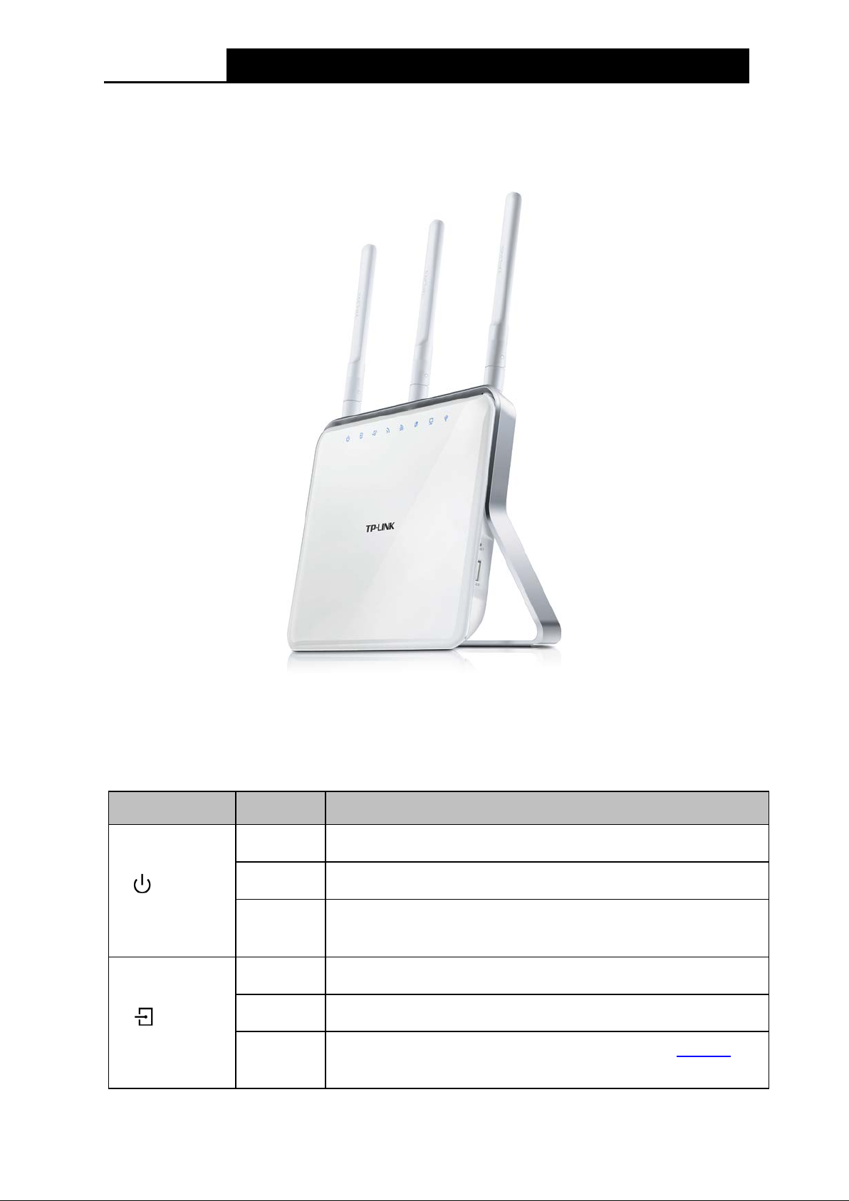
1.3.1 The Front Panel
Figure 1-1
The modem router’s LED s are located on the top panel (View fr om top to bottom). They i ndicate
the device’ s worki ng status. For details, pl ease refer to LED Explanation.
LED Explanation:
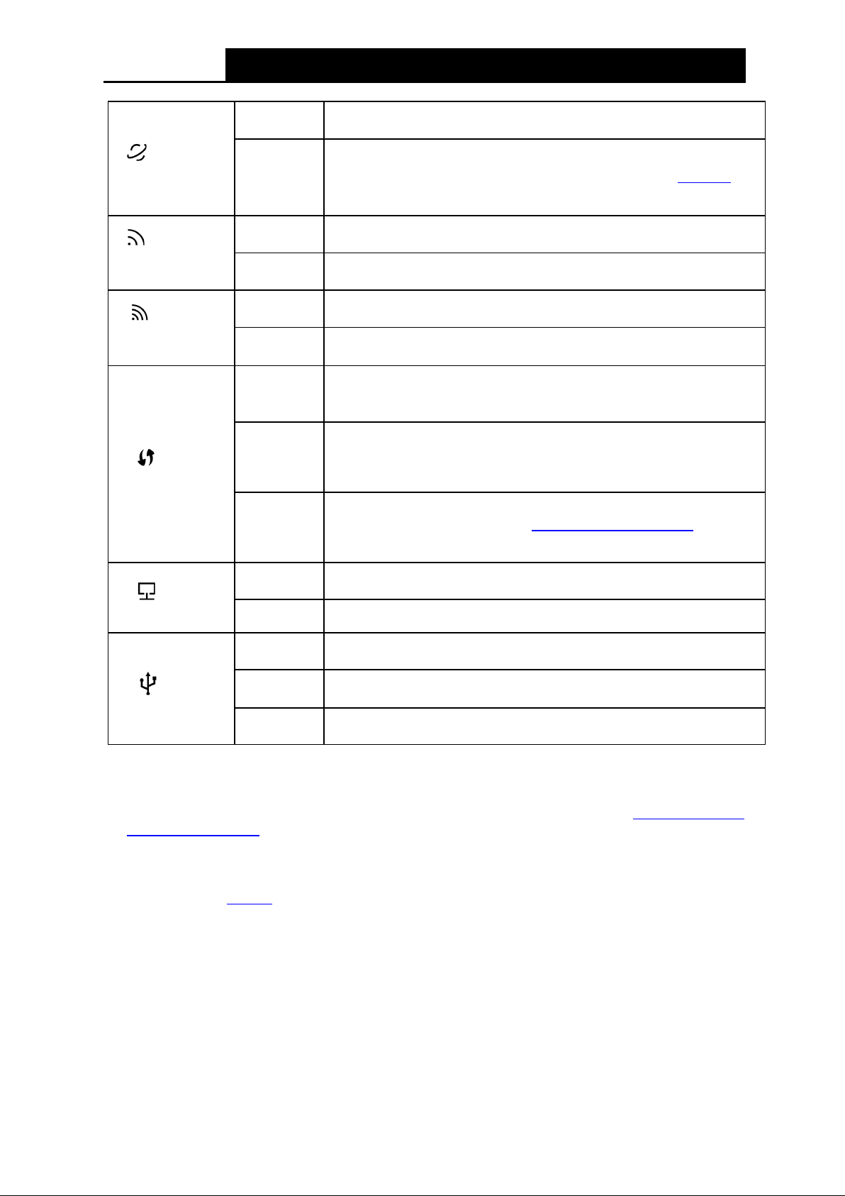
Name Status Indication
(Power)
On
System start-up compl ete.
Flashing
Sys tem starting up or device updating.
Off
Power is off. Please ensure that the power adapter
is connected
correctly.
(ADSL)
On
ADSL line is synchronized and ready to use.
Flashing
The ADS L negotiation is i n progress.
Off
ADSL synchronization fails. Please refer to Note 1
for
troubleshooting.
4
Archer D9
A C1900 Wireless Dual Band Gigabit A DS L 2+ Modem Router User Guide
(Internet)
On
The netw ork is availabl e w i th a successful Internet connection.
Off
There is no successful Internet connection or the modem router
is operating in Bridge mode. Please refer to Note 2 for
troubleshooting.
(Wireless
2.4GHz)
On
The w ireless 2.4GHz band is working properly.
Off
The 2.4GHz wireless function is disabled.
(Wireless
5GHz)
On
The w ireless 5GHz band is wor k ing properly.
Off
The 5GH z w i reless function is disabled.
(WPS)
On
A wireless device has been successfully added to the network by
WPS function.
Flashing
WPS handshaking is in process and will continue for about 2
minutes. Please press the WPS
button on other wireless devices
that you want to add to the network while the LED is flashing.
Off
A wireless device has failed to be added to the network by WPS
function. Please refer to 4.8.2 WPS Settings
for more
information.
(LAN)
On
At least one LAN port is connected.
Off No LAN port is connected.
(USB)
On
At least one USB por t is connected.
Flashing
The USB port is sending or receivi ng data.
Off
No USB port is connected.
Note:
1. If the ADSL LED is off, please check your Internet connection first. Refer to 2 .3 C onne c t ing
the Modem Router for more information about how to make Internet connection correctly. If
you have already made a right connection, please contact your ISP to make sure your Internet
service is availabl e now .
2. If the Internet LED is off, please check your ADSL LED first. If your ADSL LED is also off,
please refer to Note 1
. If your ADSL LED is ON, please check your Internet configuration. You
may need to check this par t of information with your ISP and make sure everything have been
input correctl y.
5
Archer D9
A C1900 Wireless Dual Band Gigabit A DS L 2+ Modem Router User Guide
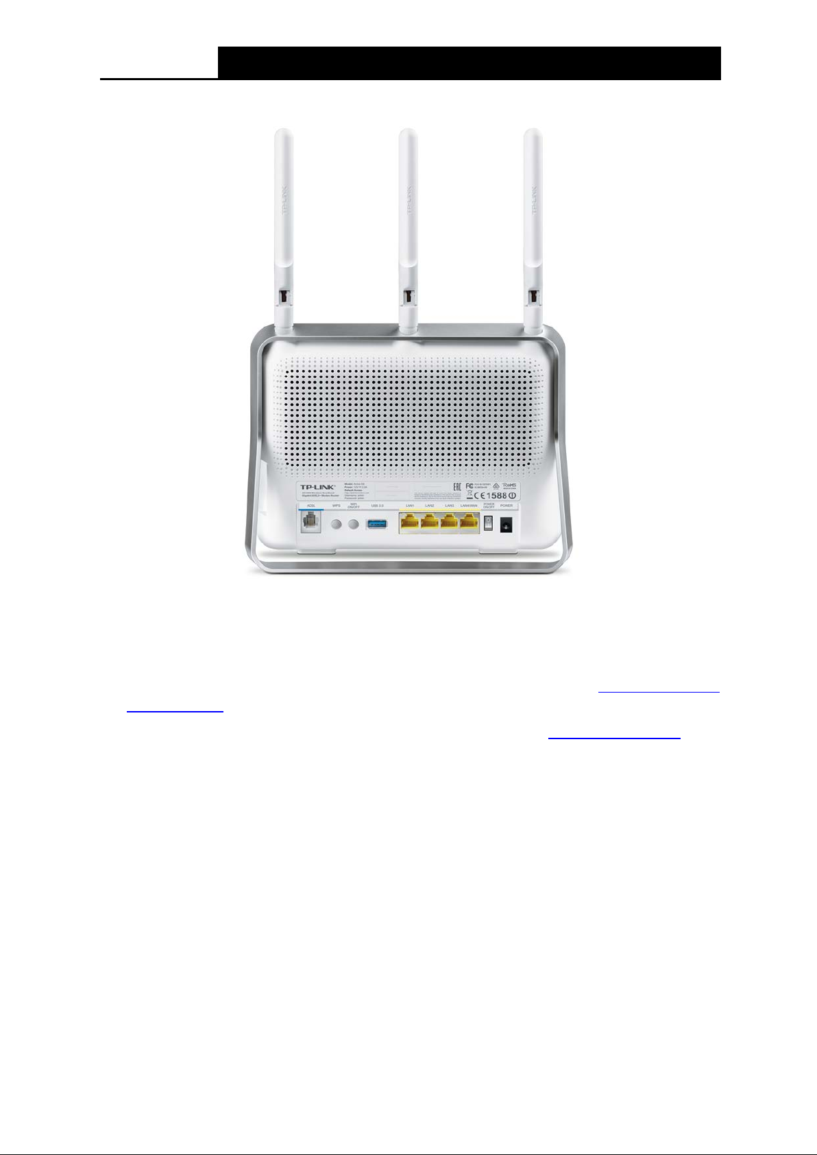
1.3.2 The Back Panel
Figure 1-2
The following parts are located on the rear panel (View from left to right).
ADSL: Through the port, you can connect the telephone to the modem router. Or yo u ca n
connect them by an external separate splitter. For details, please refer to
2.3 Connecting the
Modem Router.
WPS: The sw i tch for the WPS function. For details, pleas e refer to 4.8.2 WPS Settings.
WiFi ON/OFF: The swi tch for the WiFi func tion. Press it to enable/disable t he WiFi function.
USB 3.0: The US B 3.0 port connects to a US B 3.0 storage devi ce or a US B 3.0 printer.
LAN1, LAN2, LAN3, LAN4/WAN: Through these ports, you can connect the modem router to
your PC or other Ethernet network devices. In wireless router mode you will be able to
connect to Cable/FTTH/VDSL/ADSL devices.
POWER ON/OFF: The swi tch for the pow er.
POWER: The Power plug is where you will connect the power adapter.
Antennas: Used for w ireles s operation and data transmi t.
The following parts are located on the side panel (View from top to bottom).
USB 2.0: The US B 2.0 port connects to a U S B 2.0 storage dev ice or a US B 2.0 printer.
RESET: There are tw o ways to reset the modem router's factory defaults.
6

Archer D9
A C1900 Wireless Dual Band Gigabit A DS L 2+ Modem Router User Guide
Me t ho d one : With the modem router powered on, use a pin to press and hold the RESET
button for at least 8-10 seconds. And the modem router will reboot to its factory default
settings.
Method two : Restore the default setting from 4.23.7 Factory Defaults of the modem router's
Web-based Management.
7

Archer D9
A C1900 Wireless Dual Band Gigabit A DS L 2+ Modem Router User Guide
Chapter 2. Connecting the Modem Router
2.1 System R equireme nts
Broadband Internet A cces s Service (DS L/Cabl e/Et hernet).
PCs wi t h a worki ng Ethernet Adapter and an Ethernet cable w i th RJ45 connectors.
TCP/ I P protocol on each P C.
Web browser, such as Microsoft Internet Explorer, Mozilla F irefox and Apple Safari.
2.2 Inst allat ion Environm ent Requirement s
The Produc t should not be located w here it w i ll be ex posed to moi sture or exces sive heat.
Place the modem router in a location where it can be connected to the various devices as well
as to a power source.
Make sure the cables and power cord are safely placed out of the way so they do not cr eate a
tripping hazard.
The modem router can be placed on a shelf or desktop.
Keep away from the strong electromagnetic radiation and the device of electromagnetic
sensitive.
2.3 Connecting the Modem Router
Before installing the device, please make sure your broadband service provided by your ISP is
available. If there is any problem, please contact your ISP. Before cable connection, cut off the
pow er supply and keep your hands dry. Y ou can follow the steps bel ow to install it.
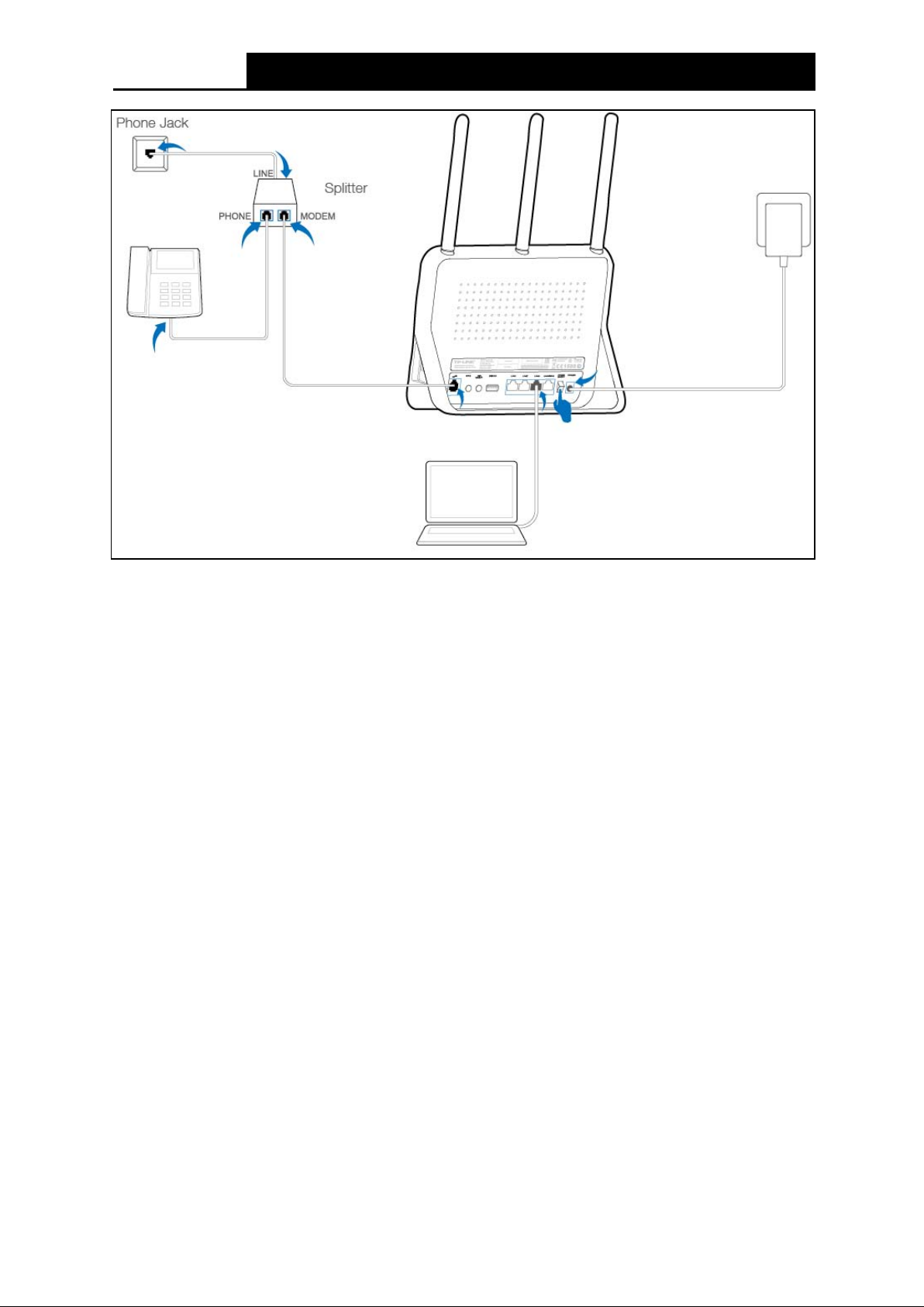
Step 1: Connect the A DS L Line.
Meth od on e: Pl ug one end of the twi sted-pair ADSL cable into the ADSL port on the rear
panel of Archer D9, and insert the other end into the Phone Jack.
Method two
:
You can use a separate splitter. External splitter can divide the data and
voice, and then you can access the Internet and make calls at the same time. The
ex ternal splitter has three ports:
• LINE: Connect to the P hone J ack
• PHONE: Connect to the phone sets
• MODEM: Connect to the ADSL port of Archer D9
Plug one end of the twisted-pair ADSL cable into the ADSL port on the rear panel of
Archer D9. Connect the other end to the MOD EM port of the external spli tter.
Step 2: Connect the Ethernet cable. Attach one end of a network cable to your computer’s
Ethernet port or a regular hub/switch port, and the other end to the LAN port on the
modem r outer Archer D9.
Step 3: Pow er on the comput ers and LAN devices.
Step 4: Attach the power adapter. Connect the power adapter to the power connector on the rear
of the device and plug in the adapter to an electrical outlet or power extension. The
electric al outlet shall be instal led near the device and shall be easil y accessible.
8
Archer D9
A C1900 Wireless Dual Band Gigabit A DS L 2+ Modem Router User Guide
Figure 2-1
9
Archer D9
A C1900 Wireless Dual Band Gigabit A DS L 2+ Modem Router User Guide
Chapter 3. Quick Installation G uid e
This chapter will show you ho w to configure the basic functions of your Archer D9 AC1900
Wirel ess Dual Band Gigabit A DS L2+ Modem Router using Quick Setup Wizard w i thin m inut es.
3.1 TCP/IP Configuration
The default IP address of the Arch er D 9 AC1900 Wireless Dual Band Gigabit ADSL2+ Modem
Router is 192.168.1.1. And the default Subnet Mask is 255.255.255.0. These values can be
changed as you desire. In this guide, we use all the default val ues for description.
Connect the local PC to the LAN/WAN port of the modem router. And then you can configure your
PC in the following way.
1) Set up the TCP/IP Protocol in "Obtain an IP address automatically" mode on your PC.
If you need instructions as to how to do this, please refer to T3 in
Appendix B:
Troubleshooting.
2) Then the built-in DHCP server w i ll assign IP address for the PC.
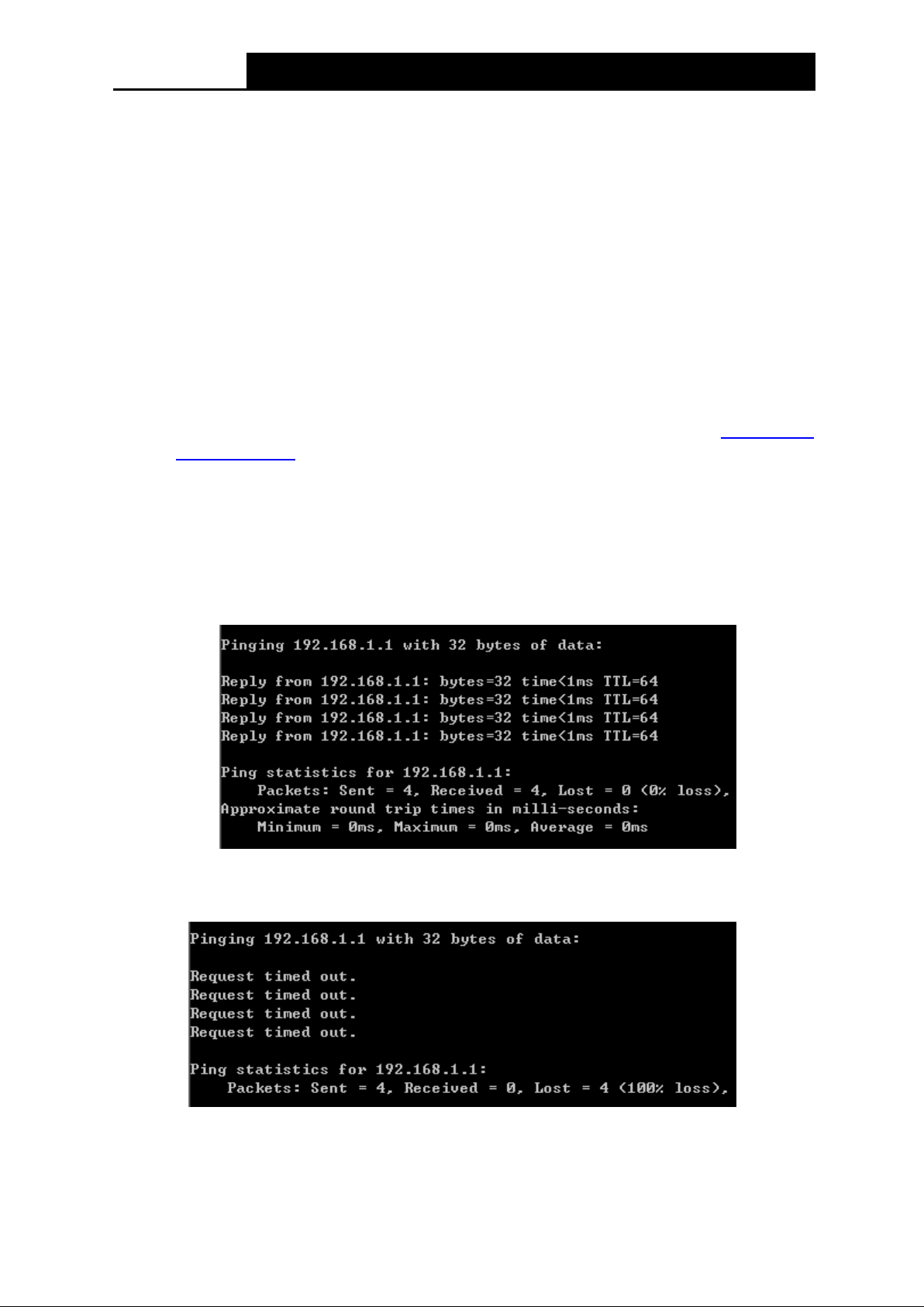
No w, you can run the Ping command in the command prompt to verify the network connection.
Please c lick the Start menu on your desktop, select run tab, type cmd or command in th e field
and press Enter. Type p ing 192.168.1.1 on the nex t screen, and then press Enter.
If the result displayed is similar to the screen below, the connection between your PC and the
router has been establi shed.
If the result displayed is similar to the screen shown below, it means that your PC has not
connected to the router.
You can check it following the steps below :
1) Is the connection be twee n y our P C a nd the router correct?
10
Archer D9
A C1900 Wireless Dual Band Gigabit A DS L 2+ Modem Router User Guide
The LEDs of LAN port which you link to the device and the LEDs on your PC's adapter should
be lit.
2) Is the T CP / IP confi guratio n for your PC c orrect?
If the router's IP address is 192.168.1.1, your PC's IP address must be within the range of
192.168.1.2 ~ 192.168.1. 254.
3.2 Quick Installation Guide
With a Web-based utility, it is easy to configure and manage the Archer D9 AC1900 Wireless Dual
Band Gigabit ADSL2+ Modem Router. The Web-based utility can be used on any Windows,
Macintosh or UNIX OS with a Web browser, such as Microsoft Internet Explorer, Mozilla Firefox or
Apple Safari.
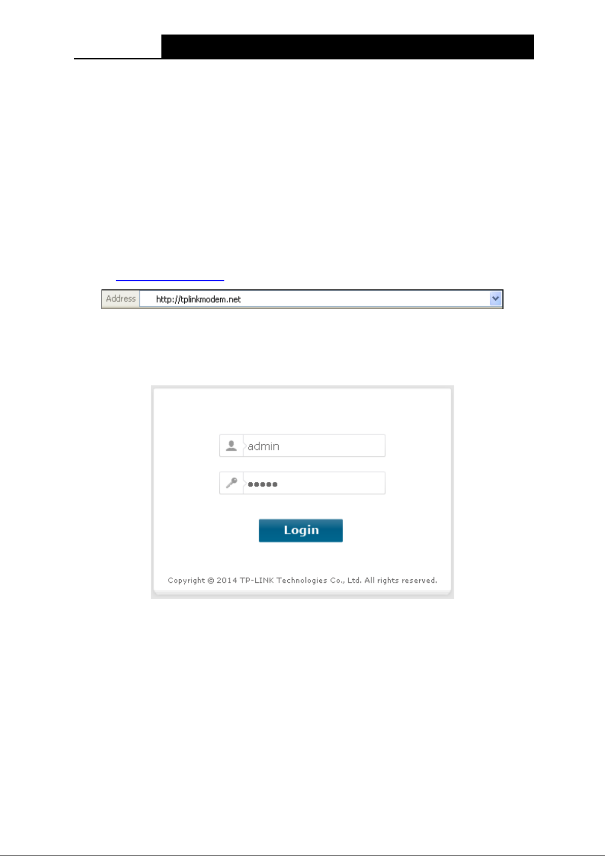
Step 1. To access the configuration utility, open a web-browser and type the default address
http://tplinkmodem.net/
in the address fiel d of the browser.
Figure 3-1
After a moment, a login window will appear, similar to the Figure 3-2. Enter admin for the
User Name and Password, both in lower case letters. Then click the Login button or
press the Enter key.
Figure 3-2
Note:
1) Do not mi x up the user name and password with your ADSL account user name and password
which are needed for PP P connections .
2) If the above screen does not pop up, it means that your Web-browser has been set to a pr oxy.
Go to Tools menu→Internet Options→Connections→LAN Settings, in the screen that
appears, cancel the U si ng Prox y checkbox , and click OK to finish it.
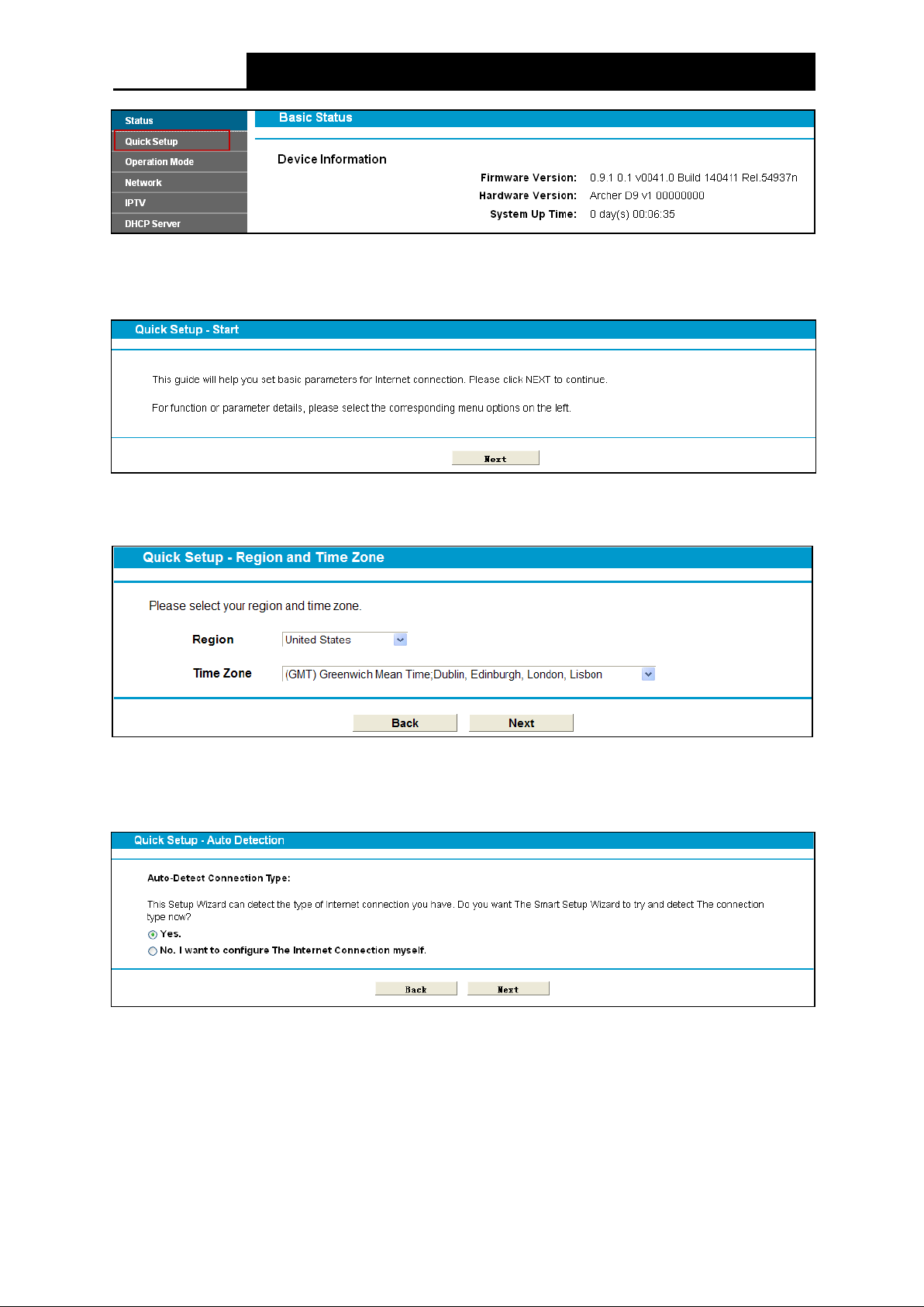
Step 2. After your successful login, you will see the Login screen as shown in Figure 3-3. Click
Quick Setup menu to access Quick Setup Wizard.
11
Archer D9
A C1900 Wireless Dual Band Gigabit A DS L 2+ Modem Router User Guide
Figure 3-3
Step 3. The Quick Setup page will appear for you to quickly configure your modem router. Click
Next to continue.
Figure 3-4
Step 4. Select the Region and the Time Zone from the drop-dow n l ist, and then click Next.
Figure 3-5
Step 5. Select Yes to auto detect your connection type and then click Next. It will t ake about two
minutes, please wait.
Figure 3-6
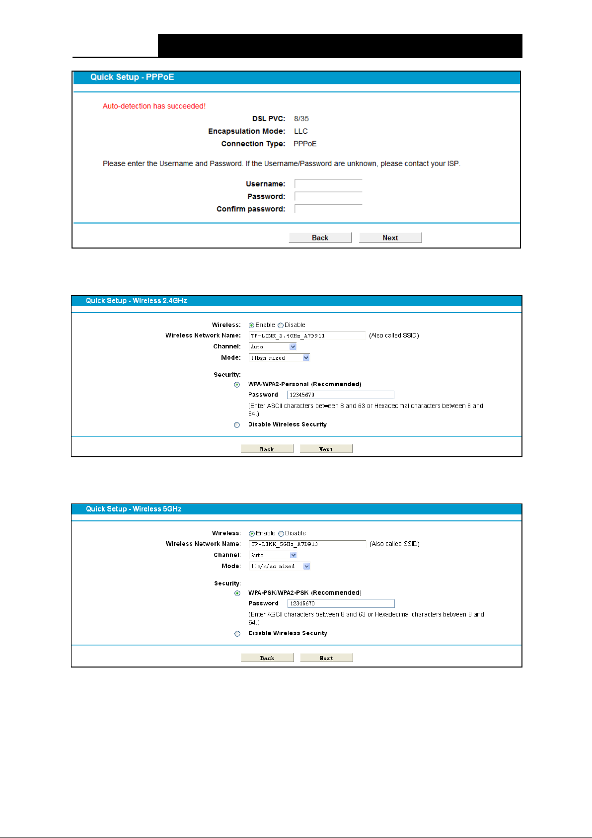
Step 6. Configure parameters for WAN connection. Here we take PPPoE as an example. Enter
usernam e and password provided by your I SP and click Next to c ontinue.
12
Archer D9
A C1900 Wireless Dual Band Gigabit A DS L 2+ Modem Router User Guide
Figure 3-7
Step 7. Configure the bas ic parameters for 2.4GHz w ireless network, and then clic k Next.
Figure 3-8
Step 8. Configure the bas ic parameters for 5GHz w ireless network and then cl ick Next.
Figure 3-9
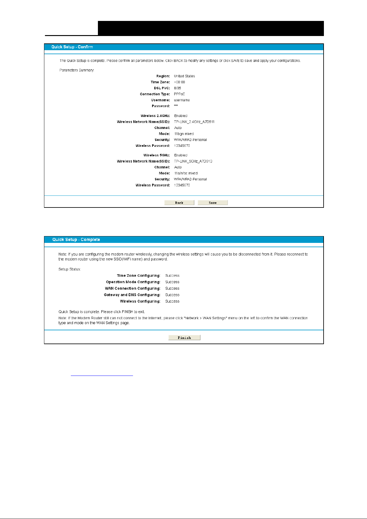
Step 9. On this page, please confirm all parameters. Click Save and wait a moment for your
settings taking effect.
13
Archer D9
A C1900 Wireless Dual Band Gigabit A DS L 2+ Modem Router User Guide
Figure 3-10
Step 10. You will see the Complete screen below. Click Finish to complete these setti ngs.
Figure 3-11
The basic settings for your modem router are completed. Please open the web browser and try to
log on to http://www.tp-link.com
to tes t your Internet connect ion.
14
Archer D9
A C1900 Wireless Dual Band Gigabit A DS L 2+ Modem Router User Guide
Chapter 4. Configuring the Modem Router
This chapter will show configuration for the key functions on the Web-based m anagem ent page.
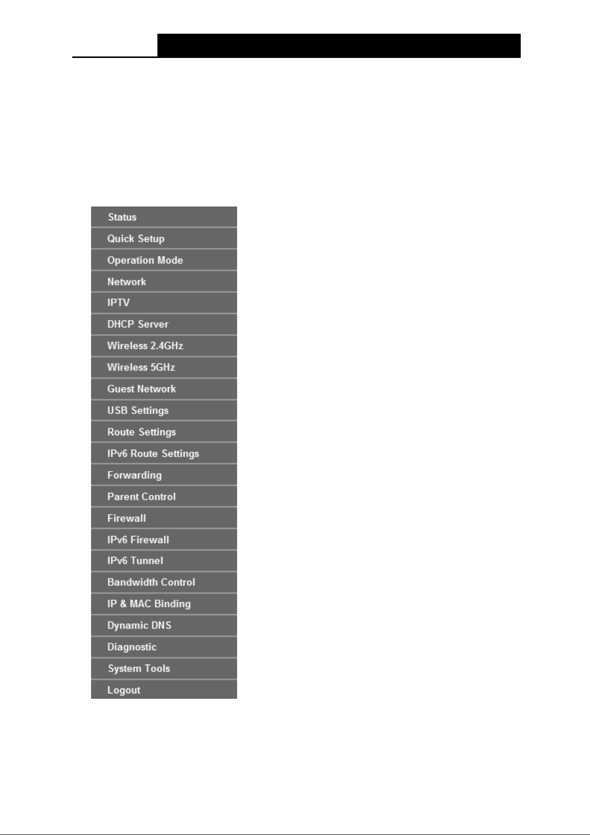
4.1 Login
After your successful login, you will see the twenty-three main menus on the left of the Web-based
utili ty. On the right, there are the corresponding explanations and inst ructions.
The detailed ex pl anations for each Web page’s key function are list ed below .
15

Archer D9
A C1900 Wireless Dual Band Gigabit A DS L 2+ Modem Router User Guide
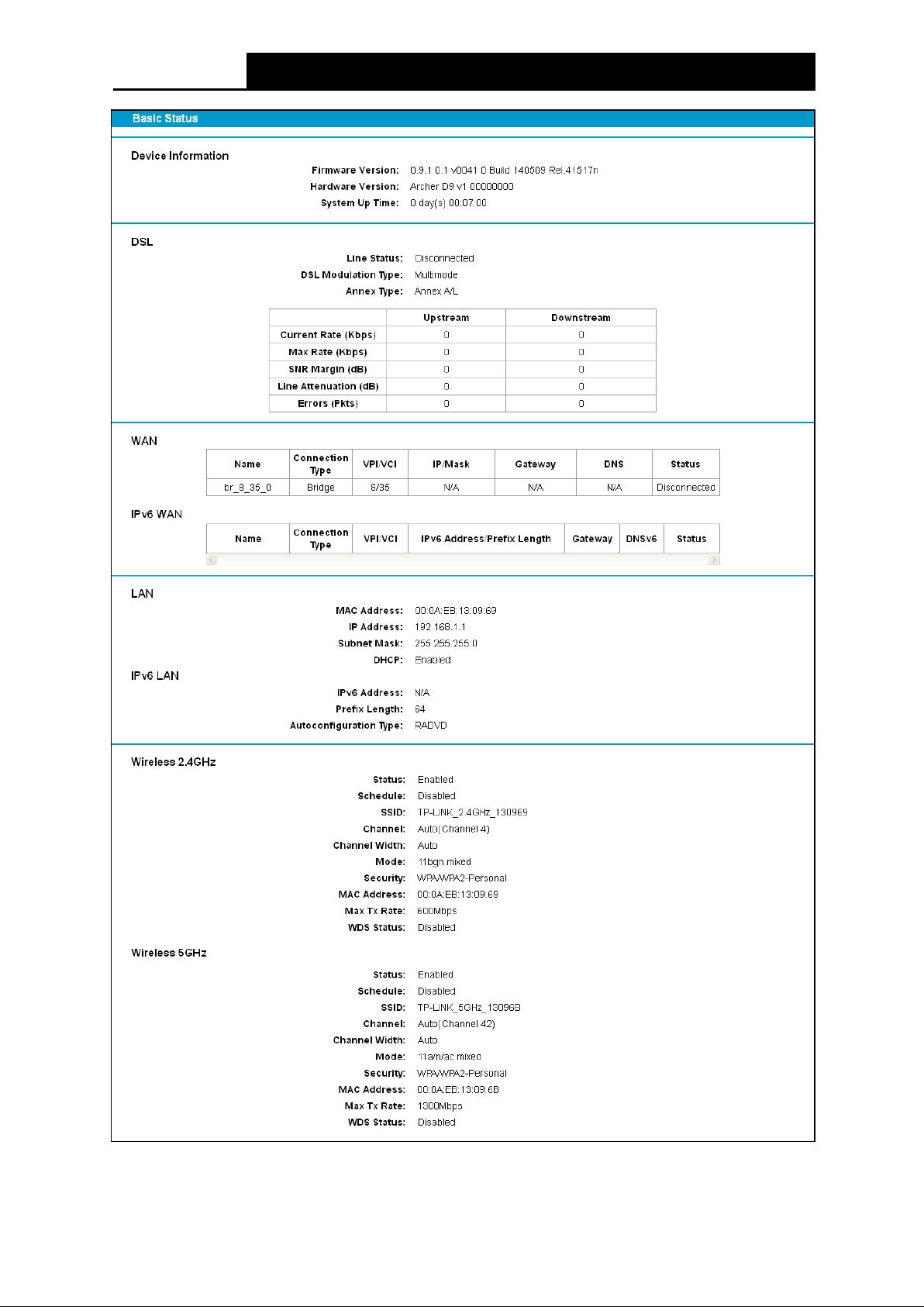
4.2 Status
Choose “Status”, you can see the corresponding information about Device Information, DSL,
WAN, LAN and Wireless.
16
Archer D9
A C1900 Wireless Dual Band Gigabit A DS L 2+ Modem Router User Guide
Figure 4-1
17
Archer D9
A C1900 Wireless Dual Band Gigabit A DS L 2+ Modem Router User Guide
4.3 Quick Setup
Pleas e refer to 3.2 Quick Installation Guide.
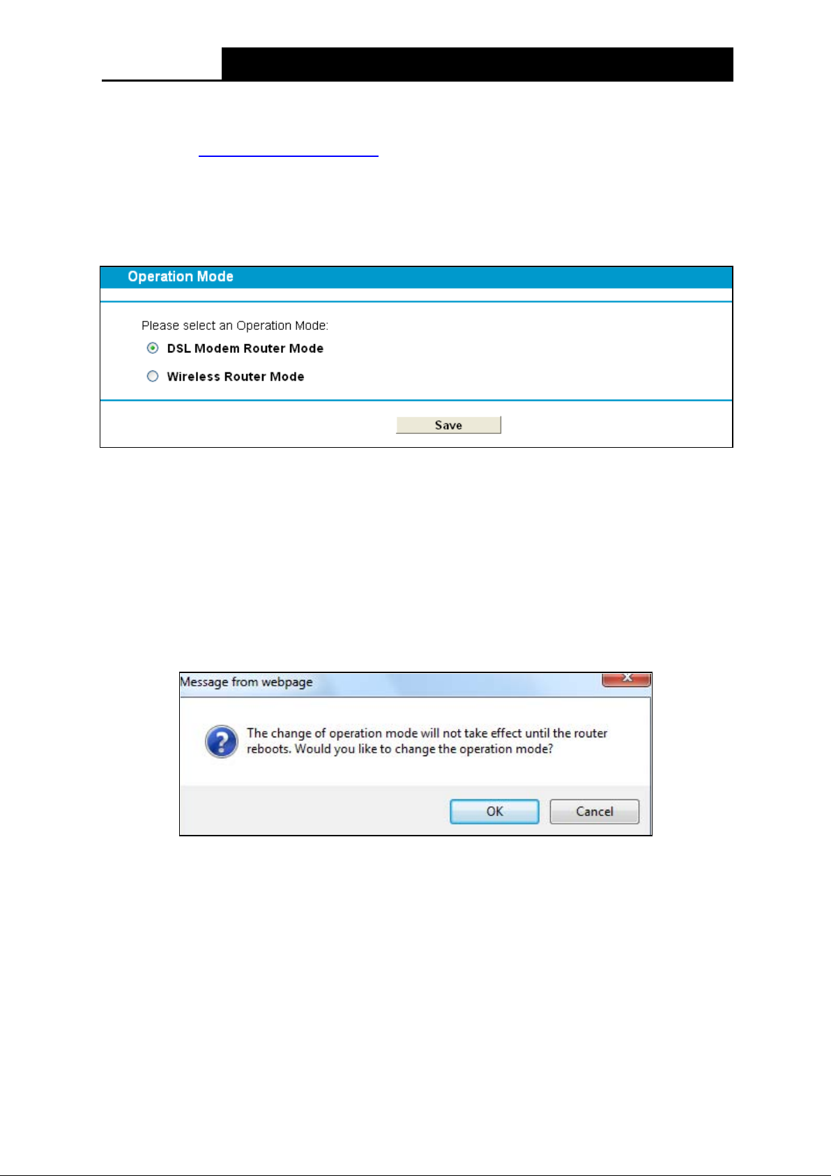
4.4 Operation Mode
Choose “Operation Mode”, and you will see the screen as shown in Figure 4-2. Select your
desired m ode and then click Save.
Figure 4-2
DSL Modem Router Mode: The devi ce enables mul ti-users to s hare I nternet via A DS L using
its ADSL port and share it wirelessly at 1300Mbps wireless speeds over the crystal clear 5GHz
band and 600Mbps over the 2.4GH z band.
Wireless Router Mode: The device enables m ulti-users to s hare I nternet via Ethernet WA N
(EWAN) using its interchangeable LA N 4/WA N port and share it wi relessl y at 1300Mbps
wireless speeds over the crystal clear 5GHz band and 600Mbps ov er the 2.4GH z band.
After you click the Save button, the Note Dialog will appear. Click OK and then the modem router
will re boot. Please wait.
Note Dialog
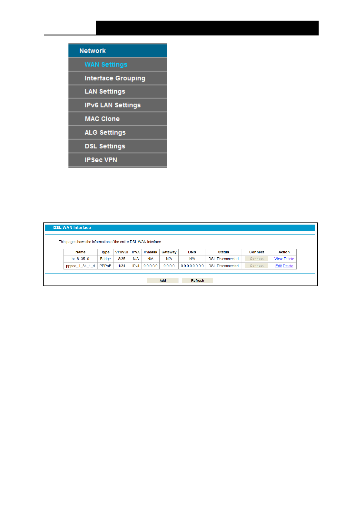
4.5 Network
Choose “Network”, there are many submenus under the main menu. Click any one of them, and
you w i ll be able to configure the corresponding f unction.
18
Archer D9
A C1900 Wireless Dual Band Gigabit A DS L 2+ Modem Router User Guide
4.5.1 WAN S e ttin g s
Choose “Network”“WAN Settings”, and you will see the WAN Port Information Table in the
screen similar to Figure 4-3. There are six different configurations for the connection types, which
are Static IP, Dyn amic I P, PPPoE, PPPo A, IPoA and Bridge. You can select the corresponding
types according to your needs.
Figure 4-3
Click Add to add a new entry, you can configure the param eters for ATM and WAN Service in the
next screen (shown in Figure 4-4).
19
Loading...