


 Loading...
User Manual
TDS 684A, TDS 744A & TDS 784A
Digitizing Oscilloscopes
070-8991-02
This document applies for firmware version 1.0 and above.
Copyright Tektronix, Inc. 1994. All rights reserved. Licensed software products are owned by Tektronix or its suppliers and are protected by United States copyright laws and international treaty provisions.
Use, duplication, or disclosure by the Government is subject to restrictions as set forth in subparagraph (c)(1)(ii) of the Rights in Technical Data and Computer Software clause at DFARS 252.227-7013, or subparagraphs (c)(1) and (2) of the Commercial Computer Software ± Restricted Rights clause at FAR 52.227-19, as applicable.
Tektronix products are covered by U.S. and foreign patents, issued and pending. Information in this publication supercedes that in all previously published material. Specifications and price change privileges reserved.
Printed in the U.S.A.
Tektronix, Inc., P.O. Box 1000, Wilsonville, OR 97070±1000
TEKTRONIX, TEK, FastFrame , FlexFormat , and InstaVu are registered trademarks of Tektronix, Inc.
WARRANTY
Tektronix warrants that this product will be free from defects in materials and workmanship for a period of three (3) years from the date of shipment. If any such product proves defective during this warranty period, Tektronix, at its option, either will repair the defective product without charge for parts and labor, or will provide a replacement in exchange for the defective product.
In order to obtain service under this warranty, Customer must notify Tektronix of the defect before the expiration of the warranty period and make suitable arrangements for the performance of service. Customer shall be responsible for packaging and shipping the defective product to the service center designated by Tektronix, with shipping charges prepaid. Tektronix shall pay for the return of the product to Customer if the shipment is to a location within the country in which the Tektronix service center is located. Customer shall be responsible for paying all shipping charges, duties, taxes, and any other charges for products returned to any other locations.
This warranty shall not apply to any defect, failure or damage caused by improper use or improper or inadequate maintenance and care. Tektronix shall not be obligated to furnish service under this warranty a) to repair damage resulting from attempts by personnel other than Tektronix representatives to install, repair or service the product; b) to repair damage resulting from improper use or connection to incompatible equipment; or c) to service a product that has been modified or integrated with other products when the effect of such modification or integration increases the time or difficulty of servicing the product.
THIS WARRANTY IS GIVEN BY TEKTRONIX WITH RESPECT TO THIS PRODUCT IN LIEU OF ANY OTHER WARRANTIES, EXPRESSED OR IMPLIED. TEKTRONIX AND ITS VENDORS DISCLAIM ANY IMPLIED WARRANTIES OF MERCHANTABILITY OR FITNESS FOR A PARTICULAR PURPOSE.
TEKTRONIX' RESPONSIBILITY TO REPAIR OR REPLACE DEFECTIVE PRODUCTS IS THE SOLE AND EXCLUSIVE REMEDY PROVIDED TO THE CUSTOMER FOR BREACH OF THIS WARRANTY. TEKTRONIX AND ITS VENDORS WILL NOT BE LIABLE FOR ANY INDIRECT, SPECIAL, INCIDENTAL, OR CONSEQUENTIAL DAMAGES IRRESPECTIVE OF WHETHER TEKTRONIX OR THE VENDOR HAS ADVANCE NOTICE OF THE POSSIBILITY OF SUCH DAMAGES.

German Postal Information
Certificate of the Manufacturer/Importer
We hereby certify that the TDS 684A, TDS 744A, and TDS 784A Digitizing Oscilloscopes and all factory-installed options comply with the RF Interference Suppression requirements of Postal Regulation Vfg. 243/1991, amended per Vfg. 46/1992.
The German Postal Service was notified that the equipment is being marketed.
The German Postal Service has the right to re-test the series and to verify that it complies.
TEKTRONIX
Bescheinigung des Herstellers/Importeurs
Hiermit wird bescheinigt, daû das TDS 684A, TDS 744A, and TDS 784A Digitizing Oscilloscopes und alle fabrikinstallierten Optionen in Übereinstimmung mit den Bestimmungen der Amtsblatt-Verfügung Vfg. 243/1991 und Zusatzverfügung 46/1992 funkentstört sind.
Der Deutschen Bundespost wurde das Inverkehrbringen dieses Gerätes angezeigt und die Berechtigung zur Überprüfung der Serie auf Einhalten der Bestimmungen eingeräumt.
TEKTRONIX
NOTICE to the user/operator:
The German Postal Service requires that systems assembled by the operator/user of this instrument must also comply with Postal Regulation, Vfg. 243/1991, Par. 2, Sect. 1.
HINWEIS für den Benutzer/Betreiber:
Die vom Betreiber zusammengestellte Anlage, innerhalb derer dieses Gerät eingesetzt wird, muû ebenfalls den Voraussetzungen nach Par. 2, Ziff. 1 der Vfg. 243/1991, genügen.
NOTICE to the user/operator:
The German Postal Service requires that this equipment, when used in a test setup, may only be operated if the requirements of Postal Regulation, Vfg. 243/1991, Par. 2, Sect. 1.8.1 are complied with.
HINWEIS für den Benutzer/Betreiber:
Dieses Gerät darf in Meûaufbauten nur betrieben werden, wenn die Voraussetzungen des Par. 2, Ziff. 1. 8.1 der Vfg. 243/1991 eingehalten werden.

EC Declaration of Conformity
We
Tektronix Holland N.V.
Marktweg 73A
8444 AB Heerenveen
The Netherlands
declare under sole responsibility that the
TDS 684A, TDS 744A, and TDS 784A Digitizing Oscilloscopes
meet the intent of Directive 89/336/EEC for Electromagnetic Compatibility. Compliance was demonstrated to the following specifications as listed in the official Journal of the European Communities:
EN 50081±1 Emissions: |
|
EN 55022 |
Radiated, Class B |
EN 55022 |
Radiated, Class B |
EN 60555±2 |
Power Harmonics |
EN 50082±1 Immunity: |
|
IEC 801±2 |
Electrostatic Discharge |
IEC 801±3 |
RF Radiated |
IEC 801±4 |
Fast Transients |
IEC 801±5 |
Surge |

Table of Contents
General Safety Summary . . . . . . . . . . . . . . . . . . . . . . . . . . . . . . . . . . . . |
ix |
Preface . . . . . . . . . . . . . . . . . . . . . . . . . . . . . . . . . . . . . . . . . . . . . . . . . . . |
xiii |
Related Manuals . . . . . . . . . . . . . . . . . . . . . . . . . . . . . . . . . . . . . . . . . . . . . . . . . . |
xiii |
Conventions . . . . . . . . . . . . . . . . . . . . . . . . . . . . . . . . . . . . . . . . . . . . . . . . . . . . . |
xiv |
Default Model . . . . . . . . . . . . . . . . . . . . . . . . . . . . . . . . . . . . . . . . . . . . . . . . . . . |
xiv |
Getting Started |
|
Product Description . . . . . . . . . . . . . . . . . . . . . . . . . . . . . . . . . . . . . . . . . |
1±1 |
Product Specification . . . . . . . . . . . . . . . . . . . . . . . . . . . . . . . . . . . . . . . . . . . . . . |
1±2 |
Start Up . . . . . . . . . . . . . . . . . . . . . . . . . . . . . . . . . . . . . . . . . . . . . . . . . . |
1±3 |
Preparation . . . . . . . . . . . . . . . . . . . . . . . . . . . . . . . . . . . . . . . . . . . . . . . . . . . . . . |
1±3 |
Putting into Service . . . . . . . . . . . . . . . . . . . . . . . . . . . . . . . . . . . . . . . . . . . . . . . |
1±4 |
Operating Basics |
|
Overview . . . . . . . . . . . . . . . . . . . . . . . . . . . . . . . . . . . . . . . . . . . . . . . . . . |
2±1 |
Operating Interface Maps . . . . . . . . . . . . . . . . . . . . . . . . . . . . . . . . . . . |
2±3 |
Tutorial . . . . . . . . . . . . . . . . . . . . . . . . . . . . . . . . . . . . . . . . . . . . . . . . . . . |
2±9 |
Setting Up for the Examples . . . . . . . . . . . . . . . . . . . . . . . . . . . . . . . . . . . . . . . . |
2±9 |
Example 1: Displaying a Waveform . . . . . . . . . . . . . . . . . . . . . . . . . . . . . . . . . . |
2±13 |
Example 2: Displaying Multiple Waveforms . . . . . . . . . . . . . . . . . . . . . . . . . . . . |
2±15 |
Example 3: Taking Automated Measurements . . . . . . . . . . . . . . . . . . . . . . . . . . |
2±19 |
Example 4: Saving Setups . . . . . . . . . . . . . . . . . . . . . . . . . . . . . . . . . . . . . . . . . . |
2±24 |
Reference |
|
Overview . . . . . . . . . . . . . . . . . . . . . . . . . . . . . . . . . . . . . . . . . . . . . . . . . . |
3±1 |
Acquiring and Displaying Waveforms . . . . . . . . . . . . . . . . . . . . . . . . . |
3±3 |
Coupling Waveforms to the Oscilloscope . . . . . . . . . . . . . . . . . . . . . . . . . . . . . . |
3±3 |
Setting up Automatically: Autoset and Reset . . . . . . . . . . . . . . . . . . . . . . . . . . . |
3±5 |
Selecting Channels . . . . . . . . . . . . . . . . . . . . . . . . . . . . . . . . . . . . . . . . . . . . . . . . |
3±7 |
Scaling and Positioning Waveforms . . . . . . . . . . . . . . . . . . . . . . . . . . . . . . . . . . |
3±9 |
Choosing an Acquisition Mode . . . . . . . . . . . . . . . . . . . . . . . . . . . . . . . . . . . . . . |
3±16 |
Customizing the Display . . . . . . . . . . . . . . . . . . . . . . . . . . . . . . . . . . . . . . . . . . . |
3±27 |
Customizing the Display Color . . . . . . . . . . . . . . . . . . . . . . . . . . . . . . . . . . . . . . |
3±33 |
Zooming on Waveforms . . . . . . . . . . . . . . . . . . . . . . . . . . . . . . . . . . . . . . . . . . . . |
3±37 |
Using InstaVu Acquisition Mode (TDS 700A Models Only) . . . . . . . . . . . . . . . |
3±43 |
Using FastFrame (TDS 700A Models Only) . . . . . . . . . . . . . . . . . . . . . . . . . . . . |
3±46 |
Triggering on Waveforms . . . . . . . . . . . . . . . . . . . . . . . . . . . . . . . . . . . . |
3±49 |
Triggering Concepts . . . . . . . . . . . . . . . . . . . . . . . . . . . . . . . . . . . . . . . . . . . . . . . |
3±49 |
Triggering from the Front Panel . . . . . . . . . . . . . . . . . . . . . . . . . . . . . . . . . . . . . |
3±53 |
Triggering on a Waveform Edge . . . . . . . . . . . . . . . . . . . . . . . . . . . . . . . . . . . . . |
3±57 |
Triggering Based on Logic . . . . . . . . . . . . . . . . . . . . . . . . . . . . . . . . . . . . . . . . . . |
3±60 |
Triggering on Pulses . . . . . . . . . . . . . . . . . . . . . . . . . . . . . . . . . . . . . . . . . . . . . . . |
3±70 |
TDS 684A, TDS 744A, & TDS 784A User Manual |
i |

Table of Contents
Delayed Triggering . . . . . . . . . . . . . . . . . . . . . . . . . . . . . . . . . . . . . . . . . . . . . . . |
3±80 |
Measuring Waveforms . . . . . . . . . . . . . . . . . . . . . . . . . . . . . . . . . . . . . . |
3±87 |
Taking Automated Measurements . . . . . . . . . . . . . . . . . . . . . . . . . . . . . . . . . . . . |
3±87 |
Taking Cursor Measurements . . . . . . . . . . . . . . . . . . . . . . . . . . . . . . . . . . . . . . . |
3±97 |
Taking Graticule Measurements . . . . . . . . . . . . . . . . . . . . . . . . . . . . . . . . . . . . . |
3±101 |
Optimizing Measurement Accuracy: SPC and Probe Cal . . . . . . . . . . . . . . . . . . |
3±102 |
Saving Waveforms and Setups . . . . . . . . . . . . . . . . . . . . . . . . . . . . . . . . |
3±111 |
Saving and Recalling Setups . . . . . . . . . . . . . . . . . . . . . . . . . . . . . . . . . . . . . . . . |
3±111 |
Saving and Recalling Waveforms . . . . . . . . . . . . . . . . . . . . . . . . . . . . . . . . . . . . |
3±114 |
Managing the File System . . . . . . . . . . . . . . . . . . . . . . . . . . . . . . . . . . . . . . . . . . |
3±117 |
Printing a Hardcopy . . . . . . . . . . . . . . . . . . . . . . . . . . . . . . . . . . . . . . . . . . . . . . . |
3±120 |
Communicating with Remote Instruments . . . . . . . . . . . . . . . . . . . . . . . . . . . . . . |
3±128 |
Determining Status and Accessing Help . . . . . . . . . . . . . . . . . . . . . . . . |
3±133 |
Displaying Status . . . . . . . . . . . . . . . . . . . . . . . . . . . . . . . . . . . . . . . . . . . . . . . . . |
3±133 |
Displaying Help . . . . . . . . . . . . . . . . . . . . . . . . . . . . . . . . . . . . . . . . . . . . . . . . . . |
3±135 |
Using Features for Advanced Applications . . . . . . . . . . . . . . . . . . . . . . |
3±137 |
Limit Testing . . . . . . . . . . . . . . . . . . . . . . . . . . . . . . . . . . . . . . . . . . . . . . . . . . . . |
3±137 |
Waveform Math . . . . . . . . . . . . . . . . . . . . . . . . . . . . . . . . . . . . . . . . . . . . . . . . . . |
3±142 |
Fast Fourier Transforms . . . . . . . . . . . . . . . . . . . . . . . . . . . . . . . . . . . . . . . . . . . . |
3±144 |
Waveform Differentiation . . . . . . . . . . . . . . . . . . . . . . . . . . . . . . . . . . . . . . . . . . |
3±161 |
Waveform Integration . . . . . . . . . . . . . . . . . . . . . . . . . . . . . . . . . . . . . . . . . . . . . |
3±165 |
Appendices |
|
Appendix A: Options and Accessories . . . . . . . . . . . . . . . . . . . . . . . . . . |
A±1 |
Appendix B: Algorithms . . . . . . . . . . . . . . . . . . . . . . . . . . . . . . . . . . . . . |
B±1 |
Appendix C: Packaging for Shipment . . . . . . . . . . . . . . . . . . . . . . . . . . |
C±1 |
Appendix D: Factory Initialization Settings . . . . . . . . . . . . . . . . . . . . . |
D±1 |
Appendix E: Probe Selection . . . . . . . . . . . . . . . . . . . . . . . . . . . . . . . . . |
E±1 |
Glossary
Index
ii |
TDS 684A, TDS 744A, & TDS 784A User Manual |

Table of Contents
List of Figures
Figure 1±1: Rear Panel Controls Used in Start Up . . . . . . . . . . . . . . . |
1±4 |
Figure 1±2: ON/STBY Button . . . . . . . . . . . . . . . . . . . . . . . . . . . . . . . . |
1±5 |
Figure 2±1: Connecting a Probe for the Examples (P6245 shown) . . |
2±9 |
Figure 2±2: SETUP Button Location . . . . . . . . . . . . . . . . . . . . . . . . . . . |
2±10 |
Figure 2±3: The Setup Menu . . . . . . . . . . . . . . . . . . . . . . . . . . . . . . . . . |
2±10 |
Figure 2±4: Trigger Controls . . . . . . . . . . . . . . . . . . . . . . . . . . . . . . . . . |
2±11 |
Figure 2±5: The Display After Factory Initialization . . . . . . . . . . . . . |
2±12 |
Figure 2±6: The VERTICAL and HORIZONTAL Controls . . . . . . . |
2±13 |
Figure 2±7: TRIGGER Controls . . . . . . . . . . . . . . . . . . . . . . . . . . . . . . |
2±14 |
Figure 2±8: AUTOSET Button Location . . . . . . . . . . . . . . . . . . . . . . . . |
2±14 |
Figure 2±9: The Display After Pressing Autoset . . . . . . . . . . . . . . . . . |
2±15 |
Figure 2±10: Display Signals Requiring Probe Compensation . . . . . . |
2±15 |
Figure 2±11: The Channel Buttons and Lights . . . . . . . . . . . . . . . . . . . |
2±16 |
Figure 2±12: The Vertical Main Menu and Coupling Side Menu . . . . |
2±17 |
Figure 2±13: The Menus After Changing Channels . . . . . . . . . . . . . . |
2±18 |
Figure 2±14: Measure Main Menu and Select Measurement |
|
Side Menu . . . . . . . . . . . . . . . . . . . . . . . . . . . . . . . . . . . . . . . . . . . . . |
2±20 |
Figure 2±15: Four Simultaneous Measurement Readouts . . . . . . . . . |
2±21 |
Figure 2±16: General Purpose Knob Indicators . . . . . . . . . . . . . . . . . |
2±22 |
Figure 2±17: Snapshot of Channel 1 . . . . . . . . . . . . . . . . . . . . . . . . . . . |
2±23 |
Figure 2±18: Save/Recall Setup Menu . . . . . . . . . . . . . . . . . . . . . . . . . . |
2±25 |
Figure 3±1: How Probe Compensation Affects Signals . . . . . . . . . . . . |
3±4 |
Figure 3±2: P6139A Probe Adjustment . . . . . . . . . . . . . . . . . . . . . . . . . |
3±4 |
Figure 3±3: The Channel Readout . . . . . . . . . . . . . . . . . . . . . . . . . . . . . |
3±8 |
Figure 3±4: Waveform Selection Priority . . . . . . . . . . . . . . . . . . . . . . . |
3±9 |
Figure 3±5: Scaling and Positioning . . . . . . . . . . . . . . . . . . . . . . . . . . . |
3±10 |
Figure 3±6: Vertical Readouts and Channel Menu . . . . . . . . . . . . . . . |
3±11 |
Figure 3±7: Record View and Time Base Readouts . . . . . . . . . . . . . . . |
3±13 |
Figure 3±8: Horizontal Controls . . . . . . . . . . . . . . . . . . . . . . . . . . . . . . |
3±14 |
Figure 3±9: Acquisition: Input Analog Signal, Sample, |
|
and Digitize . . . . . . . . . . . . . . . . . . . . . . . . . . . . . . . . . . . . . . . . . . . . |
3±17 |
Figure 3±10: Several Points May be Acquired for Each |
|
Point Used . . . . . . . . . . . . . . . . . . . . . . . . . . . . . . . . . . . . . . . . . . . . . |
3±17 |
TDS 684A, TDS 744A, & TDS 784A User Manual |
iii |

Table of Contents
Figure 3±11: Real-Time Sampling . . . . . . . . . . . . . . . . . . . . . . . . . . . . . |
3±17 |
Figure 3±12: Equivalent-Time Sampling . . . . . . . . . . . . . . . . . . . . . . . |
3±18 |
Figure 3±13: How the Acquisition Modes Work . . . . . . . . . . . . . . . . . |
3±21 |
Figure 3±14: Acquisition Menu and Readout . . . . . . . . . . . . . . . . . . . . |
3±23 |
Figure 3±15: Acquire Menu Ð Stop After . . . . . . . . . . . . . . . . . . . . . . |
3±25 |
Figure 3±16: Aliasing . . . . . . . . . . . . . . . . . . . . . . . . . . . . . . . . . . . . . . . . |
3±27 |
Figure 3±17: Display Menu Ð Style . . . . . . . . . . . . . . . . . . . . . . . . . . . |
3±29 |
Figure 3±18: Trigger Point and Level Indicators . . . . . . . . . . . . . . . . . |
3±30 |
Figure 3±19: Display Menu Ð Setting . . . . . . . . . . . . . . . . . . . . . . . . . |
3±33 |
Figure 3±20: Display Menu Ð Palette Colors . . . . . . . . . . . . . . . . . . . |
3±35 |
Figure 3±21: Display Menu Ð Map Reference Colors . . . . . . . . . . . . |
3±36 |
Figure 3±22: Display Menu Ð Restore Colors . . . . . . . . . . . . . . . . . . . |
3±37 |
Figure 3±23: Zoom Mode with Horizontal Lock Set to None . . . . . . . |
3±39 |
Figure 3±24: Dual Window (Preview) Mode . . . . . . . . . . . . . . . . . . . . . |
3±41 |
Figure 3±25: Dual Zoom Ð Shown in Dual Window (Preview) |
|
Mode . . . . . . . . . . . . . . . . . . . . . . . . . . . . . . . . . . . . . . . . . . . . . . . . . . |
3±42 |
Figure 3±26: Normal DSO Acquisition and Display Mode Versus InstaVu |
|
Mode . . . . . . . . . . . . . . . . . . . . . . . . . . . . . . . . . . . . . . . . . . . . . . . . . . |
3±44 |
Figure 3±27: InstaVu Display . . . . . . . . . . . . . . . . . . . . . . . . . . . . . . . . . |
3±45 |
Figure 3±28: Fast Frame . . . . . . . . . . . . . . . . . . . . . . . . . . . . . . . . . . . . . |
3±46 |
Figure 3±29: Horizontal Menu Ð FastFrame Setup . . . . . . . . . . . . . . |
3±47 |
Figure 3±30: Triggered Versus Untriggered Displays . . . . . . . . . . . . . |
3±49 |
Figure 3±31: Trigger Holdoff Time Ensures Valid Triggering . . . . . . |
3±52 |
Figure 3±32: Slope and Level Controls Help Define the Trigger . . . . |
3±53 |
Figure 3±33: TRIGGER Controls and Status Lights . . . . . . . . . . . . . . |
3±54 |
Figure 3±34: Example Trigger Readouts Ð Edge Trigger |
|
Selected . . . . . . . . . . . . . . . . . . . . . . . . . . . . . . . . . . . . . . . . . . . . . . . . |
3±56 |
Figure 3±35: Record View, Trigger Position, and Trigger Level Bar |
|
Readouts . . . . . . . . . . . . . . . . . . . . . . . . . . . . . . . . . . . . . . . . . . . . . . . |
3±56 |
Figure 3±36: Edge Trigger Readouts . . . . . . . . . . . . . . . . . . . . . . . . . . . |
3±57 |
Figure 3±37: Main Trigger Menu Ð Edge Type . . . . . . . . . . . . . . . . . |
3±58 |
Figure 3±38: Violation Zones for Setup/Hold Triggering . . . . . . . . . . |
3±63 |
Figure 3±39: Logic Trigger Readouts Ð State Class Selected . . . . . . |
3±64 |
Figure 3±40: Logic Trigger Menu . . . . . . . . . . . . . . . . . . . . . . . . . . . . . |
3±65 |
Figure 3±41: Logic Trigger Menu Ð Time Qualified TRUE . . . . . . . |
3±67 |
Figure 3±42: Triggering on a Setup/Hold Time Violation . . . . . . . . . . |
3±70 |
Figure 3±43: Pulse Trigger Readouts . . . . . . . . . . . . . . . . . . . . . . . . . . |
3±71 |
Figure 3±44: Main Trigger Menu Ð Glitch Class . . . . . . . . . . . . . . . . |
3±73 |
Figure 3±45: Main Trigger Menu Ð Runt Class . . . . . . . . . . . . . . . . . |
3±75 |
iv |
TDS 684A, TDS 744A, & TDS 784A User Manual |
Table of Contents
Figure 3±46: Main Trigger Menu Ð Slew Rate Class . . . . . . . . . . . . . |
3±79 |
Figure 3±47: Delayed Runs After Main . . . . . . . . . . . . . . . . . . . . . . . . . |
3±81 |
Figure 3±48: Delayed Triggerable . . . . . . . . . . . . . . . . . . . . . . . . . . . . . |
3±81 |
Figure 3±49: How the Delayed Triggers Work . . . . . . . . . . . . . . . . . . . |
3±82 |
Figure 3±50: Delayed Trigger Menu . . . . . . . . . . . . . . . . . . . . . . . . . . . |
3±84 |
Figure 3±51: Graticule, Cursor and Automated Measurements . . . . |
3±87 |
Figure 3±52: Measurement Readouts . . . . . . . . . . . . . . . . . . . . . . . . . . |
3±90 |
Figure 3±53: Measure Menu . . . . . . . . . . . . . . . . . . . . . . . . . . . . . . . . . . |
3±91 |
Figure 3±54: Measure Menu Ð Gating . . . . . . . . . . . . . . . . . . . . . . . . . |
3±92 |
Figure 3±55: Measure Menu Ð Reference Levels . . . . . . . . . . . . . . . . |
3±93 |
Figure 3±56: Measure Delay Menu Ð Delay To . . . . . . . . . . . . . . . . . . |
3±94 |
Figure 3±57: Snapshot Menu and Readout . . . . . . . . . . . . . . . . . . . . . . |
3±96 |
Figure 3±58: Cursor Types . . . . . . . . . . . . . . . . . . . . . . . . . . . . . . . . . . . |
3±97 |
Figure 3±59: Cursor Modes . . . . . . . . . . . . . . . . . . . . . . . . . . . . . . . . . . |
3±98 |
Figure 3±60: H Bars Cursor Menu and Readouts . . . . . . . . . . . . . . . . |
3±99 |
Figure 3±61: Paired Cursor Menu and Readouts . . . . . . . . . . . . . . . . |
3±100 |
Figure 3±62: Performing a Signal Path Compensation . . . . . . . . . . . . |
3±104 |
Figure 3±63: Probe Cal Menu and Gain Compensation Display . . . . |
3±106 |
Figure 3±64: Re-use Probe Calibration Data Menu . . . . . . . . . . . . . . . |
3±108 |
Figure 3±65: Save/Recall Setup Menu . . . . . . . . . . . . . . . . . . . . . . . . . . |
3±112 |
Figure 3±66: Save Waveform Menu . . . . . . . . . . . . . . . . . . . . . . . . . . . |
3±115 |
Figure 3±67: More Menu . . . . . . . . . . . . . . . . . . . . . . . . . . . . . . . . . . . . |
3±116 |
Figure 3±68: File Utilities . . . . . . . . . . . . . . . . . . . . . . . . . . . . . . . . . . . . |
3±118 |
Figure 3±69: File System Ð Labeling Menu . . . . . . . . . . . . . . . . . . . . . |
3±119 |
Figure 3±70: Utility Menu Ð System I/O . . . . . . . . . . . . . . . . . . . . . . . |
3±122 |
Figure 3±71: Hardcopy Formats . . . . . . . . . . . . . . . . . . . . . . . . . . . . . . |
3±123 |
Figure 3±72: Date and Time Display . . . . . . . . . . . . . . . . . . . . . . . . . . . |
3±124 |
Figure 3±73: Connecting the Oscilloscope Directly to the |
|
Hardcopy Device . . . . . . . . . . . . . . . . . . . . . . . . . . . . . . . . . . . . . . . . |
3±125 |
Figure 3±74: Connecting the Oscilloscope and |
|
Hardcopy Device Via a PC . . . . . . . . . . . . . . . . . . . . . . . . . . . . . . . . |
3±127 |
Figure 3±75: Typical GPIB Network Configuration . . . . . . . . . . . . . . |
3±129 |
Figure 3±76: Stacking GPIB Connectors . . . . . . . . . . . . . . . . . . . . . . . |
3±130 |
Figure 3±77: Connecting the Oscilloscope to a Controller . . . . . . . . . |
3±131 |
Figure 3±78: Utility Menu . . . . . . . . . . . . . . . . . . . . . . . . . . . . . . . . . . . . |
3±132 |
Figure 3±79: Status Menu Ð System . . . . . . . . . . . . . . . . . . . . . . . . . . |
3±134 |
Figure 3±80: Banner Display . . . . . . . . . . . . . . . . . . . . . . . . . . . . . . . . . |
3±134 |
Figure 3±81: Initial Help Screen . . . . . . . . . . . . . . . . . . . . . . . . . . . . . . |
3±135 |
Figure 3±82: Comparing a Waveform to a Limit Template . . . . . . . . |
3±137 |
TDS 684A, TDS 744A, & TDS 784A User Manual |
v |

Table of Contents
Figure 3±83: Acquire Menu Ð Create Limit Test Template . . . . . . . . |
3±139 |
Figure 3±84: More Menu . . . . . . . . . . . . . . . . . . . . . . . . . . . . . . . . . . . . |
3±142 |
Figure 3±85: Dual Waveform Math Main and Side Menus . . . . . . . . |
3±143 |
Figure 3±86: System Response to an Impulse . . . . . . . . . . . . . . . . . . . . |
3±146 |
Figure 3±87: Define FFT Waveform Menu . . . . . . . . . . . . . . . . . . . . . . |
3±147 |
Figure 3±88: FFT Math Waveform in Math1 . . . . . . . . . . . . . . . . . . . . |
3±148 |
Figure 3±89: Cursor Measurement of an FFT Waveform . . . . . . . . . . |
3±150 |
Figure 3±90: Waveform Record vs. FFT Time Domain Record . . . . . |
3±151 |
Figure 3±91: FFT Time Domain Record vs. |
|
FFT Frequency Domain Record . . . . . . . . . . . . . . . . . . . . . . . . . . . |
3±152 |
Figure 3±92: How Aliased Frequencies Appear in an FFT . . . . . . . . . |
3±156 |
Figure 3±93: Windowing the FFT Time Domain Record . . . . . . . . . . |
3±159 |
Figure 3±94: FFT Windows and Bandpass Characteristics . . . . . . . . |
3±161 |
Figure 3±95: Derivative Math Waveform . . . . . . . . . . . . . . . . . . . . . . . |
3±163 |
Figure 3±96: Peak-Peak Amplitude Measurement of a |
|
Derivative Waveform . . . . . . . . . . . . . . . . . . . . . . . . . . . . . . . . . . . . |
3±164 |
Figure 3±97: Integral Math Waveform . . . . . . . . . . . . . . . . . . . . . . . . . |
3±167 |
Figure 3±98: H Bars Cursors Measure an Integral Math Waveform |
3±168 |
Figure B±1: MCross Calculations . . . . . . . . . . . . . . . . . . . . . . . . . . . . . |
B±4 |
Figure B±2: Fall Time . . . . . . . . . . . . . . . . . . . . . . . . . . . . . . . . . . . . . . . |
B±7 |
Figure B±3: Rise Time . . . . . . . . . . . . . . . . . . . . . . . . . . . . . . . . . . . . . . . |
B±11 |
Figure B±4: Choosing Minima or Maxima to Use for |
|
Envelope Measurements . . . . . . . . . . . . . . . . . . . . . . . . . . . . . . . . . . |
B±13 |
Figure E±1: Typical High Voltage Probes . . . . . . . . . . . . . . . . . . . . . . . |
E±2 |
Figure E±2: A6303 Current Probe Used in the AM 503S Opt. 03 . . . |
E±4 |
vi |
TDS 684A, TDS 744A, & TDS 784A User Manual |

Table of Contents
List of Tables
Table 1±1: Key Features of the TDS Oscilloscopes . . . . . . . . . . . . . . . |
1±1 |
Table 1±2: Fuse and Fuse Cap Part Numbers . . . . . . . . . . . . . . . . . . . |
1±5 |
Table 3±1: Autoset Defaults . . . . . . . . . . . . . . . . . . . . . . . . . . . . . . . . . . |
3±6 |
Table 3±2: How Interleaving Affects Sample Rate . . . . . . . . . . . . . . . . |
3±19 |
Table 3±3: Additional Resolution Bits . . . . . . . . . . . . . . . . . . . . . . . . . |
3±22 |
Table 3±4: TDS 744A Sampling Mode Selection |
|
(When Fit to Screen is Off) . . . . . . . . . . . . . . . . . . . . . . . . . . . . . . . |
3±24 |
Table 3±5: TDS 784A Sampling Mode Selection |
|
(When Fit to Screen is Off) . . . . . . . . . . . . . . . . . . . . . . . . . . . . . . . |
3±25 |
Table 3±6: XY Format Pairs . . . . . . . . . . . . . . . . . . . . . . . . . . . . . . . . . |
3±32 |
Table 3±7: Pattern and State Logic . . . . . . . . . . . . . . . . . . . . . . . . . . . . |
3±62 |
Table 3±8: Pulse Trigger Definitions . . . . . . . . . . . . . . . . . . . . . . . . . . . |
3±71 |
Table 3±9: Measurement Definitions . . . . . . . . . . . . . . . . . . . . . . . . . . |
3±88 |
Table 3±10: Probe Cal Status . . . . . . . . . . . . . . . . . . . . . . . . . . . . . . . . |
3±109 |
Table A±1: Options . . . . . . . . . . . . . . . . . . . . . . . . . . . . . . . . . . . . . . . . . |
A±1 |
Table A±2: Standard Accessories . . . . . . . . . . . . . . . . . . . . . . . . . . . . . |
A±3 |
Table A±3: Optional Accessories . . . . . . . . . . . . . . . . . . . . . . . . . . . . . . |
A±4 |
Table A±4: Accessory Software . . . . . . . . . . . . . . . . . . . . . . . . . . . . . . . |
A±5 |
Table D±1: Factory Initialization Defaults . . . . . . . . . . . . . . . . . . . . . . |
D±1 |
TDS 684A, TDS 744A, & TDS 784A User Manual |
vii |

Table of Contents
viii |
TDS 684A, TDS 744A, & TDS 784A User Manual |

General Safety Summary
|
Review the following safety precautions to avoid injury and prevent damage to |
|
this product or any products connected to it. |
|
Only qualified personnel should perform service procedures. |
Injury Precautions |
|
Use Proper Power Cord |
To avoid fire hazard, use only the power cord specified for this product. |
Avoid Electric Overload |
To avoid electric shock or fire hazard, do not apply a voltage to a terminal that is |
|
outside the range specified for that terminal. |
Ground the Product |
This product is grounded through the grounding conductor of the power cord. To |
|
avoid electric shock, the grounding conductor must be connected to earth |
|
ground. Before making connections to the input or output terminals of the |
|
product, ensure that the product is properly grounded. |
Do Not Operate Without |
To avoid electric shock or fire hazard, do not operate this product with covers or |
Covers |
panels removed. |
Use Proper Fuse |
To avoid fire hazard, use only the fuse type and rating specified for this product. |
Do Not Operate in |
To avoid electric shock, do not operate this product in wet or damp conditions. |
Wet/Damp Conditions |
|
Do Not Operate in |
To avoid injury or fire hazard, do not operate this product in an explosive |
Explosive Atmosphere |
atmosphere. |
Keep Probe Surface Clean |
To avoid electric shock and erroneous readings, keep probe surface clean. |
Product Damage Precautions
Use Proper Power Source Do not operate this product from a power source that applies more than the voltage specified.
TDS 684A, TDS 744A, & TDS 784A User Manual |
ix |

General Safety Summary
Provide Proper Ventilation |
To prevent product overheating, provide proper ventilation. |
Do Not Operate With |
If you suspect there is damage to this product, have it inspected by qualified |
Suspected Failures |
service personnel. |
Do Not Immerse in Liquids |
Clean the probe using only a damp cloth. Refer to cleaning instructions. |
Safety Terms and Symbols
Terms in This Manual These terms may appear in this manual:
WARNING. Warning statements identify conditions or practices that could result in injury or loss of life.
CAUTION. Caution statements identify conditions or practices that could result in damage to this product or other property.
Terms on the Product These terms may appear on the product:
DANGER indicates an injury hazard immediately accessible as you read the marking.
WARNING indicates an injury hazard not immediately accessible as you read the marking.
CAUTION indicates a hazard to property including the product.
x |
TDS 684A, TDS 744A, & TDS 784A User Manual |

General Safety Summary
Symbols on the Product The following symbols may appear on the product:
DANGER |
Protective Ground |
ATTENTION |
Double |
High Voltage |
(Earth) Terminal |
Refer to |
Insulated |
|
|
Manual |
|
Certifications and Compliances
CSA Certified Power CSA Certification includes the products and power cords appropriate for use in Cords the North America power network. All other power cords supplied are approved
for the country of use.
TDS 684A, TDS 744A, & TDS 784A User Manual |
xi |

General Safety Summary
xii |
TDS 684A, TDS 744A, & TDS 784A User Manual |

Preface
This is the User Manual for the TDS 684A, TDS 744A, and TDS 784A
Digitizing Oscilloscopes.
The chapter Getting Started briefly describes the TDS Oscilloscope, prepares you to install it, and tells you how to put it into service.
The chapter Operating Basics covers basic principles of the operation of the oscilloscope. The operating interface illustrations and the tutorial examples rapidly help you understand how your oscilloscope operates.
The chapter Reference teaches you how to perform specific tasks. See page 3±1 for a complete list of operating tasks covered in that chapter.
The Appendices provide an options listing, an accessories listing, and other useful information.
Related Manuals
The following documents are related to the use or service of the oscilloscope.
HThe TDS Family Digitizing Oscilloscopes Programmer Manual (Tektronix part number 070-8709-xx) describes using a computer to control the oscilloscope through the GPIB interface.
HThe TDS 684A, TDS 744A, & TDS 784A Reference (Tektronix part number 070-8999-xx) gives you a quick overview of how to operate the oscilloscope.
HThe TDS 684A, TDS 744A, & TDS 784A Performance Verification and Specifications (Tektronix part number 070-8990-xx) tells how to verify the performance of the oscilloscope and lists its specifications.
HThe TDS Family Option 05 Video Trigger Instruction Manual (Tektronix part number 070-8748-xx) describes use of the video trigger option (for TDS oscilloscopes equipped with that option only).
HThe TDS 684A, TDS 744A, & TDS 784A Service Manual (Tektronix part number 070-8992-xx) provides information for maintaining and servicing the oscilloscope to the module level.
TDS 684A, TDS 744A, & TDS 784A User Manual |
xiii |

Preface
Conventions
In this manual, you will find various procedures which contain steps of instructions for you to perform. To keep those instructions clear and consistent, this manual uses the following conventions:
HIn procedures, names of front panel controls and menu labels appear in boldface print.
HNames also appear in the same case (initial capitals or all uppercase) in the manual as is used on the oscilloscope front panel and menus. Front panel names are all upper case letters, for example, VERTICAL MENU and CH 1.
HInstruction steps are numbered. The number is omitted if there is only one step.
HWhen steps require that you make a sequence of selections using front panel controls and menu buttons, an arrow ( ) marks each transition between a front panel button and a menu, or between menus. Also, whether a name is a main menu or side menu item is clearly indicated: Press VERTICAL MENU Coupling (main) DC (side) Bandwidth (main)
250 MHz (side).
Using the convention just described results in instructions that are graphically intuitive and simplifies procedures. For example, the instruction just given replaces these five steps:
1.Press the front panel button VERTICAL MENU.
2.Press the main-menu button Coupling.
3.Press the side-menu button DC.
4.Press the main-menu button Bandwidth.
5.Press the side-menu button 250 MHz.
Sometimes you may have to make a selection from a pop-up menu: Press TRIGGER MENU Type (main) Edge (pop-up). In this example, you repeatedly press the main menu button Type until Edge is highlighted in the pop-up menu.
Default Model
This manual documents the TDS 684A, TDS 744A, and TDS 784A Digitizing Oscilloscopes. However, the TDS 684A display screen appears as the default screen wherever a display screen is illustrated in this manual. Also, this manual uses the name ªTDS 700Aº when providing information common to both the TDS 744A and TDS 784A model oscilloscopes.
xiv |
TDS 684A, TDS 744A, & TDS 784A User Manual |

Product Description
The Tektronix TDS Oscilloscope is a superb tool for acquiring, displaying, and measuring waveforms. Its performance addresses the needs of both benchtop lab and portable applications with the following features:
Table 1±1: Key Features of the TDS Oscilloscopes
|
Feature |
TDS 684A |
TDS 744A |
TDS 784A |
||||||||||
|
|
|
|
|
|
|
|
|
|
|
|
|
||
|
Digitizing rate, maxi- |
5 GS/s on each chan- |
2 GS/s |
4 GS/s |
||||||||||
|
mum |
nel simultaneously |
|
|
|
|
|
|
|
|
|
|
|
|
|
|
|
|
|
|
|
|
|
|
|
|
|
||
|
Analog bandwidth |
1 GHz |
500 MHz |
1 GHz |
||||||||||
|
|
|
|
|
|
|
|
|
|
|
|
|
|
|
|
Channels |
Four, each with 8-bit resolution |
|
|
|
|
|
|
|
|
|
|||
|
|
|
|
|
|
|
|
|
|
|
|
|||
|
Record lengths, maxi- |
15 K samples per |
Up to 50 K standard, up to 250 K (2 channels) |
|||||||||||
|
mum |
channel |
and 500 K (1 channel) with Option 1M |
|||||||||||
|
|
|
|
|
|
|
|
|
|
|
|
|||
|
Acquisition modes |
Sample, envelope, |
Sample, envelope, average, high-resolution, |
|||||||||||
|
|
and average |
and peak-detect |
|
|
|
|
|
|
|
|
|
||
|
|
|
InstaVuTM mode, which updates the display at |
|||||||||||
|
|
|
rates rivaling the fastest analog oscilloscopes |
|||||||||||
|
|
|
|
|
|
|
|
|
|
|
|
|
|
|
|
Display |
Color |
Color |
|
|
|
|
|
|
|
|
|
||
|
|
Zoom, which allows |
Dual Window Zoom, which shows a waveform |
|||||||||||
|
|
you to magnify a |
magnified and unmagnified on the same |
|||||||||||
|
|
waveform |
display |
|
|
|
|
|
|
|
|
|
||
|
|
|
|
|
|
|
|
|
|
|
|
|
|
|
|
|
|
|
|
|
|
|
|
|
|
|
|
|
|
|
|
|
|
|
|
|
|
|
|
|
|
|
|
|
|
|
|
|
|
|
|
|
|
|
|
|
|
|
|
|
|
|
|
|
|
|
|
|
|
|
|
|
|
|
|
|
|
|
|
|
|
|
|
|
|
|
|
|
|
|
|
|
|
|
|
|
|
|
|
|
|
|
|
|
|
|
|
|
|
|
|
|
|
|
|
|
|
|
|
|
|
|
|
|
|
|
|
|
|
|
|
|
|
|
TDS 684A, TDS 744A, & TDS 784A User Manual |
1±1 |

Product Description
Table 1±1: Key Features of the TDS Oscilloscopes (Cont.)
Feature |
TDS 684A |
TDS 744A |
TDS 784A |
|
|
|
|
Trigger modes |
Include: edge, logic, and pulse. Video trigger, with option 05, modes |
||
|
include: |
|
|
|
NTSC, SECAM, PAL, HDTV, and FlexFormatT. |
|
|
|
|
||
Storage |
1.44 Mbyte, 3.5 inch, DOS 3.3-or-later floppy disk. |
||
|
NVRAM storage for saving waveforms, hardcopies, and setups |
||
|
|
|
|
I/O |
Full GPIB programmability. |
|
|
|
Hardcopy output using GPIB, RS-232, or Centronics ports |
||
|
|
|
|
Product Specification
The product specification is found in the technical reference TDS 684A,
TDS 744A, & TDS 784A Performance Verification and Specifications that is shipped as a standard accessory with the TDS Oscilloscope.
1±2 |
TDS 684A, TDS 744A, & TDS 784A User Manual |

Start Up
Before you use the TDS Oscilloscope, ensure that it is properly installed and powered on.
Preparation
To ensure maximum accuracy for your most critical measurements, you should know about signal path compensation and the proper use of the probe you choose to use with your oscilloscope.
Signal Path Compensation Be sure you compensate your oscilloscope for the surrounding temperature. This action, called Signal Path Compensation (SPC), ensures maximum possible accuracy for your most critical measurements. See Signal Path Compensation on page 3±102 for a description of and operating information on this feature.
Recommended Probes The TDS 744A Oscilloscope ships with four general-purpose, P6139A 500 MHz passive probes. The TDS 684A and TDS 784A Oscilloscopes ship without probes. To take advantage of the higher bandwidth of the TDS 684A and
TDS 784A Oscilloscopes, order the P6245 Active Probe. See Appendix A: Options and Accessories in this manual for more information on optional-acces- sory probes for all three oscilloscope models.
Probe Usage Be sure you use the appropriate probe for the measurement. For instance, do not use the P6245 Active Probe to measure signals greater than ±8 volts or with more than ±10 volts of offset since errors in signal measurement will result. (See the User manual for the probe for more information.) Instead, use a passive probe, such as P6139A passive probe, that allows higher voltage measurements. The P6139A probe is for measurements up to ±500 volts.
CAUTION. Using the P6245 Active Probe to measure signals greater than
±40 volts may damage the probe.
Input Coupling Be sure to choose the proper input coupling and impedance for the probe or other cabling you use to couple signals to your oscilloscope. You should read Input Impedance Considerations on page 3±5 for information needed to ensure proper coupling of your input signals.
TDS 684A, TDS 744A, & TDS 784A User Manual |
1±3 |
Start Up
Putting into Service
To learn how to install, access the front panel, power on, do a self test, and power off the oscilloscope, do the following procedures:
Installation To properly install and power on the oscilloscope, do the following steps:
1.Be sure you have the appropriate operating environment. Specifications for temperature, relative humidity, altitude, vibrations, and emissions are included in the TDS 684A, TDS 744A, & TDS 784A Performance Verification and Specifications manual (Tektronix part number 070-8990-xx).
2.Leave space for cooling. Do this by verifying that the air intake and exhaust holes on the sides of the cabinet (where the fan operates) are free of any airflow obstructions. Leave at least 5.1 cm (2 inches) free on each side.
WARNING. To avoid electrical shock, be sure that the power cord is disconnected before checking the fuse.
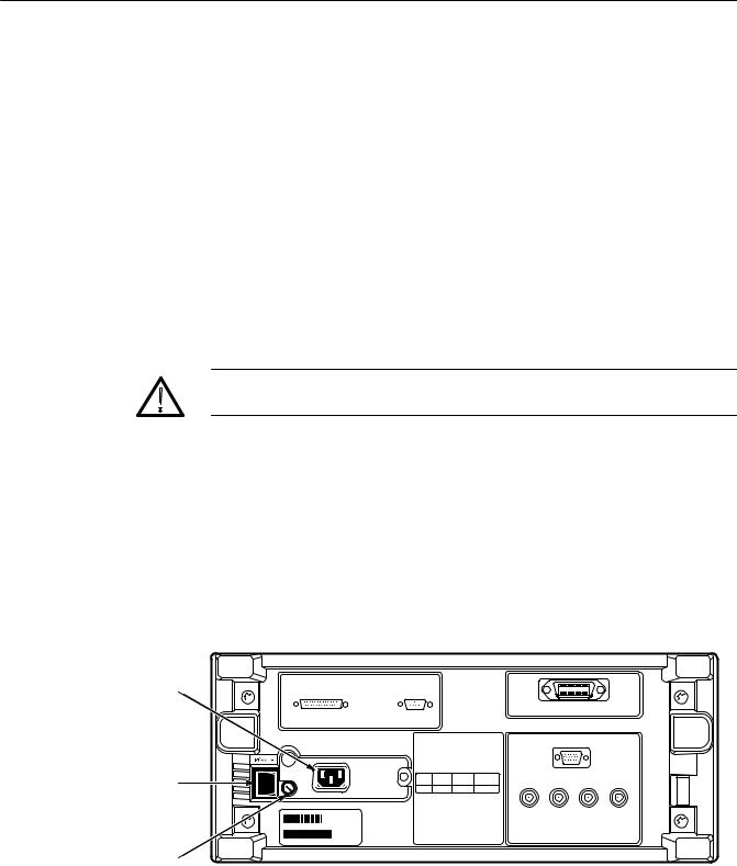
3.Check the fuse to be sure it is the proper type and rating (see Figure 1±1). You can use either of two fuses. Each fuse requires its own cap (see
Table 1±2). The oscilloscope is shipped with the UL approved fuse installed.
4.Check that you have the proper electrical connections. The oscilloscope
requires 90 to 250 VACRMS, continuous range, 45 Hz to 440 Hz, and may require up to 300 W.
5.Connect the proper power cord from the rear-panel power connector (see Figure 1±1) to the power system.
Power Connector
Principal Power Switch |
Fuse
Figure 1±1: Rear Panel Controls Used in Start Up
1±4 |
TDS 684A, TDS 744A, & TDS 784A User Manual |

Start Up
Table 1±2: Fuse and Fuse Cap Part Numbers
|
|
Fuse Cap |
Fuse |
Fuse Part Number |
Part Number |
|
|
|
0.25 inch ×1.25 inch (UL 198.6, 3AG): 6 A |
159-0013-00 |
200-2264-00 |
FAST, 250 V. |
|
|
|
|
|
5 mm ×20 mm (IEC 127): 5 A (T), 250 V. |
159-0210-00 |
200-2265-00 |
|
|
|
Front Cover Removal To remove the front cover, grasp its left and right edges and snap it off of the front subpanel. (To reinstall it, align it to the front subpanel and snap it back on.)
Power On To power on the oscilloscope, do the following steps:
1.Check that the rear-panel principal power switch is on (see Figure 1±1). The principal power switch controls all AC power to the instrument.
2.If the oscilloscope is not powered on (the screen is blank), push the front-panel ON/STBY button to toggle it on (see Figure 1±2).
ON/STBY Button
Figure 1±2: ON/STBY Button
TDS 684A, TDS 744A, & TDS 784A User Manual |
1±5 |

Start Up
The ON/STBY button controls power to most of the instrument circuits. Power continues to go to certain parts even when this switch is set to STBY.
Once the oscilloscope is installed, it is typical to leave the principal power switch on and use the ON/STBY button instead of the power switch.
Self Test The oscilloscope automatically performs power-up tests each time it is turned on. It will come up with a display screen that states whether or not it passed the self test. To determine the self test results, check the screen. (If the self test passed, the status display screen will be removed after a few seconds.)
If the self test fails, call your local Tektronix Service Center. Depending on the type of failure, you may still be able to use the oscilloscope before it is serviced.
Power Off To power off the oscilloscope, toggle the ON/STBY switch.
1±6 |
TDS 684A, TDS 744A, & TDS 784A User Manual |

Overview
This chapter describes the basic concepts of operating the TDS Oscilloscope. Understanding the basic concepts of your oscilloscope will help you use it much more effectively.
The first section, Operating Interface Maps, quickly shows you how the oscilloscope controls are organized and where you can read about them. It also illustrates the general procedures for operating the menu system. This section includes the titles:
HFront Panel Map
HRear Panel Map
HDisplay Map
HTo Operate a Menu
HTo Operate a Pop-Up Menu
The second section, Tutorial, contains example procedures that lead you through the fundamental tasks needed to display a waveform measurement. It also includes an example procedure that teaches you how to store a setup of the oscilloscope controls for later use. This section includes the following tuto-
rial examples:
HSetting Up for the Examples
HExample 1: Displaying a Waveform
HExample 2: Displaying Multiple Waveforms
HExample 3: Taking Automated Measurements
HExample 4: Saving Setups
To explore these topics in more depth and to read about topics not covered in this section, see Reference. A list of the topics covered begins on Page 3±1.
TDS 684A, TDS 744A, & TDS 784A User Manual |
2±1 |

Overview
2±2 |
TDS 684A, TDS 744A, & TDS 784A User Manual |
Loading...