


User Manual
WFM 601i
Serial Digital Component Monitor
070-8966-01
Please check for change information at the rear of this manual.
First Printing: May 1994
Revised: November 1995
Copyright Tektronix, Inc., 1994. All rights reserved. Printed in U.S.A. Tektronix products are covered by U.S. and foreign patents, issued and pending.
Information in this publication supersedes that in all previously published material. Specifications and price change privileges reserved. The following are registered trademarks: TEKTRONIX and TEK.
For further information, contact: Tektronix, Inc., Corporate Offices, P.O. Box 1000, Wilsonville, OR 97070±1000, U.S.A. Phone: (503) 627±7111; TLX: 192825; TWX: (910) 467±8708; Cable: TEKWSGT.
Tektronix' Television Division participates in the Broadcast Professionals Forum (BPFORUM) on the CompuServe Information Service. Press releases on new
products, product-specific newsletters, application information and technical papers are among the types of information uploaded.
Additionally, product specialists from Tektronix will be ªon lineº to answer questions regarding product applications, operation and maintenance.
Instructions for accessing the information on CompuServe can be found in the current Tektronix Television Products Catalog.
CompuServe access is currently available in the U.S.A., Canada, Europe, Japan, Australia, New Zealand, Argentina, Venezuela, Korea, and Taiwan.
WARRANTY
Tektronix warrants that this product, that it manufactures and sells, will be free from defects in materials and workmanship for a period of three (3) years from the date of shipment. If any such product proves defective during this warranty period, Tektronix, at its option, either will repair the defective product without charge for parts and labor, or will provide a replacement in exchange for the defective product.
In order to obtain service under this warranty, Customer must notify Tektronix of the defect before the expiration of the warranty period and make suitable arrangements for the performance of service. Customer shall be responsible for packaging and shipping the defective product to the service center designated by Tektronix, with shipping charges prepaid. Tektronix shall pay for the return of the product to Customer if the shipment is to a location within the country in which the Tektronix service center is located. Customer shall be responsible for paying all shipping charges, duties, taxes, and any other charges for products returned to any other locations.
This warranty shall not apply to any defect, failure or damage caused by improper use or improper or inadequate maintenance and care. Tektronix shall not be obligated to furnish service under this warranty a) to repair damage resulting from attempts by personnel other than Tektronix representatives to install, repair or service the product; b) to repair damage resulting from improper use or connection to incompatible equipment; c) to repair any damage or malfunction caused by the use of non-Tektronix supplies; or d) to service a product that has been modified or integrated with other products when the effect of such modification or integration increases the time or difficulty of servicing the product.
THIS WARRANTY IS GIVEN BY TEKTRONIX WITH RESPECT TO THIS PRODUCT IN LIEU OF ANY OTHER WARRANTIES, EXPRESSED OR IMPLIED. TEKTRONIX AND ITS VENDORS DISCLAIM ANY IMPLIED WARRANTIES OF MERCHANTABILITY OR FITNESS FOR A PARTICULAR PURPOSE. TEKTRONIX' RESPONSIBILITY TO REPAIR OR REPLACE DEFECTIVE PRODUCTS IS THE SOLE AND EXCLUSIVE REMEDY PROVIDED TO THE CUSTOMER FOR BREACH OF THIS WARRANTY. TEKTRONIX AND ITS VENDORS WILL NOT BE LIABLE FOR ANY INDIRECT, SPECIAL, INCIDENTAL, OR CONSEQUENTIAL DAMAGES IRRESPECTIVE OF WHETHER TEKTRONIX OR THE VENDOR HAS ADVANCE NOTICE OF THE POSSIBILITY OF SUCH DAMAGES.

EC Declaration of Conformity
We
Tektronix Holland N.V.
Marktweg 73A
8444 AB Heerenveen
The Netherlands
declare under sole responsibility that the
WFM 601i Serial Digital Component Monitor
meets the intent of Directive 89/336/EEC for Electromagnetic Compatibility. Compliance was demonstrated to the following specifications as listed in the Official Journal of the European Communities:
EN 50081-1 Emissions:
EN 55022 Class B Radiated and Conducted Emissions
EN 50082-1 Immunity:
IEC 801-2 Electrostatic Discharge Immunity
IEC 801-3 RF Electromagnetic Field Immunity
IEC 801-4 Electrical Fast Transient/Burst Immunity
High-quality shielded cables must be used to ensure compliance to the above listed standards.
This product complies when installed into any of the following Tektronix instrument enclosures:
1700F00 Standard Cabinet
1700F02 Portable Cabinet
1700F05 Rack Adapter

.8 |
|
|
.7 |
100% |
|
.6 |
|
|
.5 |
|
|
.4 |
50% |
|
.3 |
||
|
||
.2 |
|
|
.1 |
|
|
±.1 |
|
|
±.2 |
|
|
±.3 |
|
|
Tek |
COMPONENT ANALOG 2% & 4% KPB |
|
VERT POS |
HORIZ POS |
CLEAR
MENU
|
|
|
|
|
|
|
|
SERIAL COMPONENT |
||||||||||||||
|
|
|
|
|
|
|
MONITOR |
|||||||||||||||
|
|
|
|
|
|
|
|
|
DISPLAY |
|
|
|
|
|
|
|
|
|
|
|||
|
|
|
EYE |
|
|
VECTOR |
|
|
WAVEFORM |
|||||||||||||
|
|
|
|
|
|
|
||||||||||||||||
|
|
|
EQ EYE |
|
|
LIGHTNING |
|
|
PARADE |
|||||||||||||
|
|
|
|
|
|
|
||||||||||||||||
|
|
|
|
|
|
|
||||||||||||||||
|
|
|
|
|
|
|
|
|
|
|||||||||||||
|
|
|
|
|
|
|
|
|
|
|
|
|
|
|
|
|
|
|
|
|
|
|
|
|
MULTIPLE |
|
|
PICTURE |
|
|
BOWTIE |
||||||||||||||
|
|
|
|
|
|
|||||||||||||||||
|
|
|
|
|
|
|||||||||||||||||
|
|
|
|
|
|
|
|
|
|
|
|
|
|
|
|
|
|
|
|
|
|
|
|
|
|
|
|
|
|
|
|
|
|
|
|
|
|
|
|
|
|
|
|||
|
|
VIDEO IN |
|
|
|
|
SWEEP |
|
|
|
|
|
MENU |
|
|
|
|
|||||
|
|
|
|
|
|
|
|
|
LINE |
|
|
|
|
FILTER |
|
|
||||||
|
|
|
CH1 |
|
|
FIELD |
|
|
|
|
|
|
||||||||||
|
|
|
|
|
|
|
|
|
|
|
|
|
|
|
||||||||
|
|
|
|
|
|
|
|
|
|
|
|
|
|
|
|
|
CURSOR |
|
|
|||
|
|
|
CH2 |
|
|
|
MAG |
|
|
|
|
|
|
|
||||||||
|
|
|
|
|
|
|
|
|
LIN SEL |
|
|
|||||||||||
|
|
|
|
|
|
|
|
|
|
|
||||||||||||
|
|
|
|
|
|
|
|
|
|
|
|
|
|
|
|
|
|
|
||||
|
|
|
|
|
|
|
|
|
|
|
|
|
|
|
|
|
PRESET |
|
|
|||
|
|
|
CH3 |
|
|
SERIAL |
|
|
|
|
|
|
|
|
||||||||
|
|
|
|
|
|
|
|
|
|
|
|
|
||||||||||
|
|
|
|
|
|
|
|
|
|
|
CONFIG |
|
|
|||||||||
|
|
|
|
|
|
|
|
|
|
|
|
|
||||||||||
|
|
|
|
|
|
|
|
|
|
|
|
|
|
|
|
|||||||
|
|
|
|
|
|
|
|
|
|
|
|
|
|
|
|
|
|
|
|
|
|
|
|
|
|
SERIAL A |
|
|
|
|
|
|
|
|
|
|
|
||||||||
|
|
|
|
|
|
|
|
|
|
|
|
|
||||||||||
|
|
|
|
|
|
|
|
|
|
|
|
|
|
|
|
|
|
|
|
|
||
|
|
|
SERIAL B |
|
ALARM |
|
|
|
|
GAIN |
|
|
||||||||||
|
|
|
|
|
|
|
|
|
|
|
|
|
|
|
|
|
CRT |
|
|
|||
|
|
|
|
|
|
|
|
|
REF |
|
|
|
|
|
|
|
|
|
||||
|
|
|
|
|
|
|
|
|
EXT |
|
|
|
|
POWER |
|
|||||||
|
|
|
|
|
|
|
|
|
|
|
|
|
|
|||||||||
|
|
|
|
|
|
|
|
|
|
|
|
|
|
|
|
|
ON |
|
|
|
||
|
|
|
|
|
|
|
|
|
|
|
|
|
|
|
|
|
|
|
|
|||
|
|
|
|
|
|
|
|
|
|
|
|
|
|
|
|
|
|
|
|
|
|
|
|
|
|
|
|
|
|
|
|
|
|
|
|
|
|
|
|
|
|
|
|
|
|
WFM 601i Serial Digital Component Monitor

Table of Contents
List of Figures . . . . . . . . . . . . . . . . . . . . . . . . . . . . . . . . . . . . . . . . . . . . . |
iii |
List of Tables . . . . . . . . . . . . . . . . . . . . . . . . . . . . . . . . . . . . . . . . . . . . . . |
v |
Safety Summary . . . . . . . . . . . . . . . . . . . . . . . . . . . . . . . . . . . . . . . . . . . |
vii |
Manual Overview . . . . . . . . . . . . . . . . . . . . . . . . . . . . . . . . . . . . . . . . . . . . . . . . . |
ix |
Getting Started |
|
Product Description . . . . . . . . . . . . . . . . . . . . . . . . . . . . . . . . . . . . . . . . . |
1±1 |
Features . . . . . . . . . . . . . . . . . . . . . . . . . . . . . . . . . . . . . . . . . . . . . . . . . . . . . . . . |
1±1 |
Accessories . . . . . . . . . . . . . . . . . . . . . . . . . . . . . . . . . . . . . . . . . . . . . . . . . . . . . . |
1±2 |
Options . . . . . . . . . . . . . . . . . . . . . . . . . . . . . . . . . . . . . . . . . . . . . . . . . . . . . . . . . |
1±4 |
Installation . . . . . . . . . . . . . . . . . . . . . . . . . . . . . . . . . . . . . . . . . . . . . . . . |
1±5 |
Packaging . . . . . . . . . . . . . . . . . . . . . . . . . . . . . . . . . . . . . . . . . . . . . . . . . . . . . . . |
1±5 |
Packaged Accessories . . . . . . . . . . . . . . . . . . . . . . . . . . . . . . . . . . . . . . . . . . . . . |
1±6 |
Internal Jumper . . . . . . . . . . . . . . . . . . . . . . . . . . . . . . . . . . . . . . . . . . . . . . . . . . . |
1±6 |
Mechanical Installation . . . . . . . . . . . . . . . . . . . . . . . . . . . . . . . . . . . . . . . . . . . . |
1±7 |
Connecting Power . . . . . . . . . . . . . . . . . . . . . . . . . . . . . . . . . . . . . . . . . . . . . . . . |
1±13 |
Remote Control . . . . . . . . . . . . . . . . . . . . . . . . . . . . . . . . . . . . . . . . . . . . . . . . . . |
1±13 |
Installing the WFM 601i in a Serial Video System . . . . . . . . . . . . . . . . . . . . . . . |
1±14 |
Functional Check . . . . . . . . . . . . . . . . . . . . . . . . . . . . . . . . . . . . . . . . . . . |
1±17 |
Required Equipment . . . . . . . . . . . . . . . . . . . . . . . . . . . . . . . . . . . . . . . . . . . . . . . |
1±17 |
Initial Equipment Connections . . . . . . . . . . . . . . . . . . . . . . . . . . . . . . . . . . . . . . . |
1±18 |
Procedure . . . . . . . . . . . . . . . . . . . . . . . . . . . . . . . . . . . . . . . . . . . . . . . . . . . . . . . |
1±18 |
Operating Basics |
|
At A Glance . . . . . . . . . . . . . . . . . . . . . . . . . . . . . . . . . . . . . . . . . . . . . . . |
2±1 |
Front Panel Controls and Indicators . . . . . . . . . . . . . . . . . . . . . . . . . . . . . . . . . . . |
2±1 |
Rear Panel Connectors . . . . . . . . . . . . . . . . . . . . . . . . . . . . . . . . . . . . . . . . . . . . . |
2±4 |
Functional Overview . . . . . . . . . . . . . . . . . . . . . . . . . . . . . . . . . . . . . . . . |
2±7 |
Video Display Modes . . . . . . . . . . . . . . . . . . . . . . . . . . . . . . . . . . . . . . . . . . . . . . |
2±7 |
Eye Pattern Display . . . . . . . . . . . . . . . . . . . . . . . . . . . . . . . . . . . . . . . . . . . . . . . |
2±8 |
Serial Readout Screens . . . . . . . . . . . . . . . . . . . . . . . . . . . . . . . . . . . . . . . . . . . . . |
2±11 |
Using the Menus . . . . . . . . . . . . . . . . . . . . . . . . . . . . . . . . . . . . . . . . . . . . . . . . . |
2±15 |
Remote Operation . . . . . . . . . . . . . . . . . . . . . . . . . . . . . . . . . . . . . . . . . . . . . . . . |
2±22 |
Calibration . . . . . . . . . . . . . . . . . . . . . . . . . . . . . . . . . . . . . . . . . . . . . . . . . . . . . . |
2±22 |
Reference |
|
Graticules . . . . . . . . . . . . . . . . . . . . . . . . . . . . . . . . . . . . . . . . . . . . . . . . . |
3±1 |
Electronic Graticules . . . . . . . . . . . . . . . . . . . . . . . . . . . . . . . . . . . . . . . . . . . . . . |
3±3 |
Measurement Applications . . . . . . . . . . . . . . . . . . . . . . . . . . . . . . . . . . . |
3±5 |
Measuring Serial Sources . . . . . . . . . . . . . . . . . . . . . . . . . . . . . . . . . . . . . . . . . . . |
3±5 |
Monitoring Transmission Channels . . . . . . . . . . . . . . . . . . . . . . . . . . . . . . . . . . . |
3±10 |
Measuring Error Rate . . . . . . . . . . . . . . . . . . . . . . . . . . . . . . . . . . . . . . . . . . . . . . |
3±12 |
Advanced Eye Pattern Modes . . . . . . . . . . . . . . . . . . . . . . . . . . . . . . . . . . . . . . . |
3±14 |
Rev Aug 1994 |
i |
WFM 601i Serial Component Monitor |

Contents
Using the Diamond Display . . . . . . . . . . . . . . . . . . . . . . . . . . . . . . . . . . . . . . . . . |
3±16 |
Measurement Theory . . . . . . . . . . . . . . . . . . . . . . . . . . . . . . . . . . . . . . . |
3±19 |
Eye Pattern Display . . . . . . . . . . . . . . . . . . . . . . . . . . . . . . . . . . . . . . . . . . . . . . . |
3±19 |
Vector Display . . . . . . . . . . . . . . . . . . . . . . . . . . . . . . . . . . . . . . . . . . . . . . . . . . . |
3±19 |
Lightning Display . . . . . . . . . . . . . . . . . . . . . . . . . . . . . . . . . . . . . . . . . . . . . . . . . |
3±21 |
Diamond Display . . . . . . . . . . . . . . . . . . . . . . . . . . . . . . . . . . . . . . . . . . . . . . . . . |
3±23 |
Bowtie Display . . . . . . . . . . . . . . . . . . . . . . . . . . . . . . . . . . . . . . . . . . . . . . . . . . . |
3±24 |
Appendices |
|
Appendix A: Specifications . . . . . . . . . . . . . . . . . . . . . . . . . . . . . . . . . . . |
A±1 |
Appendix B: Multipin Connectors . . . . . . . . . . . . . . . . . . . . . . . . . . . . . |
B±1 |
REMOTE Connector . . . . . . . . . . . . . . . . . . . . . . . . . . . . . . . . . . . . . . . . . . . . . . |
B±1 |
RS232 Connector . . . . . . . . . . . . . . . . . . . . . . . . . . . . . . . . . . . . . . . . . . . . . . . . . |
B±3 |
Appendix C: User Service . . . . . . . . . . . . . . . . . . . . . . . . . . . . . . . . . . . . |
C±1 |
Cleaning or Replacing the Fan Filter . . . . . . . . . . . . . . . . . . . . . . . . . . . . . . . . . . |
C±1 |
Fuse Replacement . . . . . . . . . . . . . . . . . . . . . . . . . . . . . . . . . . . . . . . . . . . . . . . . |
C±1 |
Graticule Light Replacement . . . . . . . . . . . . . . . . . . . . . . . . . . . . . . . . . . . . . . . . |
C±1 |
Cleaning . . . . . . . . . . . . . . . . . . . . . . . . . . . . . . . . . . . . . . . . . . . . . . . . . . . . . . . . |
C±3 |
Replacing the CRT Filter . . . . . . . . . . . . . . . . . . . . . . . . . . . . . . . . . . . . . . . . . . . |
C±4 |
ii |
WFM 601i Serial Component Monitor |

Contents
List of Figures
Figure 1-1: Dimensions of the 1700F00 plain cabinet. . . . . . . . . . . . . . . . |
|
1±7 |
Figure 1-2: 1700F02 portable cabinet. . . . . . . . . . . . . . . . . . . . . . . . . . . . |
|
1±8 |
Figure 1-3: Rear view of the WFM 601i. . . . . . . . . . . . . . . . . . . . . . . . . . |
|
1±9 |
Figure 1-4: The 1700F05 side-by-side rack adaptor. . . . . . . . . . . . . . . . . |
|
1±10 |
Figure 1-5: Instrument in 1700F05 with blank front-panel (1700F06). . . |
|
1±10 |
Figure 1-6: 1700F05 cabinet with 1700F07 utility drawer. . . . . . . . . . . . |
|
1±11 |
Figure 1-7: Custom installation considerations. . . . . . . . . . . . . . . . . . . . . |
|
1±12 |
Figure 1-8: Monitoring the video bit stream of a serial receiver . . . . . . |
. |
1±14 |
Figure 1-9: Monitoring serial digital signals around a routing switcher. . |
|
1±15 |
Figure 1-10: Eye pattern display of a termination with good return loss. . |
|
1±16 |
Figure 1-11: Eye pattern display of a termination with poor return loss. . |
|
1±16 |
Figure 1-12: Channel 1 of color bar with level reference on the WFM 601i. 1±19 |
||
Figure 1-13: Eye pattern display. . . . . . . . . . . . . . . . . . . . . . . . . . . . . . . . |
|
1±20 |
Figure 1-14: Parade display of Y and PB. . . . . . . . . . . . . . . . . . . . . . . . . . |
|
1±21 |
Figure 1-15: Parade display of Y, PB, and PR. . . . . . . . . . . . . . . . . . . . . . |
|
1±21 |
Figure 1-16: WFM 601i on screen RGB display. . . . . . . . . . . . . . . . . . . . |
|
1±22 |
Figure 1-17: WFM601i calibrator display. . . . . . . . . . . . . . . . . . . . . . . . . |
|
1±23 |
Figure 1-18: Calibrator signal, both gains misadjusted. . . . . . . . . . . . . . . |
|
1±24 |
Figure 1-19: One field display of CH 1 (Y) signal. . . . . . . . . . . . . . . . . . |
|
1±25 |
Figure 1-20: Two field display of CH 1 (Y) signal. . . . . . . . . . . . . . . . . . |
|
1±25 |
Figure 1-21: Two Line Magnified Display. . . . . . . . . . . . . . . . . . . . . . . . . |
|
1±26 |
Figure 1-22: A two-line differentiated step display. . . . . . . . . . . . . . . . . . |
|
1±27 |
Figure 1-23: Two field line select display; line number 150 selected. . . . |
|
1±28 |
Figure 1-24: Line select, 15-line display; lines 150±164 displayed. . . . . . |
|
1±28 |
Figure 1-25: Vector color bar display with electronic graticule. . . . . . . . . |
|
1±29 |
Figure 1-26: Picture monitor display of the color bar signal. . . . . . . . . . . |
|
1±30 |
Figure 1-27: Lightning display of component color difference signals. . . |
|
1±31 |
Figure 1-28: Diamond display. . . . . . . . . . . . . . . . . . . . . . . . . . . . . . . . . . |
|
1±31 |
Figure 1-29: The Bowtie display. . . . . . . . . . . . . . . . . . . . . . . . . . . . . . . . |
|
1±32 |
Figure 2-1: WFM601i front panel. . . . . . . . . . . . . . . . . . . . . . . . . . . . . . . |
|
2±1 |
Figure 2-2: Rear panel of the WFM601i Monitor. . . . . . . . . . . . . . . . . . . |
|
2±4 |
Figure 2-3: Overlay Eye display. . . . . . . . . . . . . . . . . . . . . . . . . . . . . . . . . |
|
2±9 |
Figure 2-4: 10-EYE display screen. . . . . . . . . . . . . . . . . . . . . . . . . . . . . . |
|
2±10 |
Figure 2-5: Basic Status Screen . . . . . . . . . . . . . . . . . . . . . . . . . . . . . . . . . |
|
2±12 |
Rev Jun 1994 |
|
iii |
WFM 601i Serial Component Monitor |
|
|

Contents
Figure 2-6: Status screen with 525 line, 10-bit video. . . . . . . . . . . . . . . . |
2±13 |
Figure 2-7: Loss of signal condition is indicated. . . . . . . . . . . . . . . . . . . . |
2±13 |
Figure 2-8: Basic FORMAT Screen. . . . . . . . . . . . . . . . . . . . . . . . . . . . . . |
2±14 |
Figure 2-9: Elements of the WFM601i menu driven selections. . . . . . . . |
2±15 |
Figure 2-10: Parade display of YPBPR shown in line select. . . . . . . . . . . |
2±17 |
Figure 2-11: Configure menu screen. . . . . . . . . . . . . . . . . . . . . . . . . . . . . |
2±18 |
Figure 3-1: Waveform measurement graticule. . . . . . . . . . . . . . . . . . . . . . |
3±1 |
Figure 3-2: Vectorscope graticule. . . . . . . . . . . . . . . . . . . . . . . . . . . . . . . . |
3±3 |
Figure 3-3: Lightning display graticule. . . . . . . . . . . . . . . . . . . . . . . . . . . |
3±4 |
Figure 3-4: Graticule for the Diamond display. . . . . . . . . . . . . . . . . . . . . |
3±4 |
Figure 3-5: Measuring a source. . . . . . . . . . . . . . . . . . . . . . . . . . . . . . . . . |
3±5 |
Figure 3-6: Measuring 20±80% risetime using cursors. . . . . . . . . . . . . . . |
3±7 |
Figure 3-7: Connection for point-to-point error measurements. . . . . . . . . |
3±12 |
Figure 3-8: Construction of the Diamond Display. . . . . . . . . . . . . . . . . . . |
3±17 |
Figure 3-9: Out-of-Gamut signals as displayed by Diamond. . . . . . . . . . . |
3±18 |
Figure 3-10: Vector display relationship of the R±Y (V) and B±Y (U). . . |
3±20 |
Figure 3-11: Construction of the Lightning waveform. . . . . . . . . . . . . . . |
3±21 |
Figure 3-12: Lightning graticule showing interchannel timing errors. . . . |
3±22 |
Figure 3-13: Construction of the Diamond GBR display. . . . . . . . . . . . . . |
3±24 |
Figure 3-14: Typical Bowtie display on the WFM 601i. . . . . . . . . . . . . . . |
3±25 |
Figure B-1: REMOTE connector. . . . . . . . . . . . . . . . . . . . . . . . . . . . . . . |
B±1 |
Figure B±2: RS232 REMOTE connector. . . . . . . . . . . . . . . . . . . . . . . . . . |
B±3 |
Figure C-1: Graticule light replacement. . . . . . . . . . . . . . . . . . . . . . . . . . . |
C±2 |
iv |
Rev Aug 1994 |
WFM 601i Serial Component Monitor |
Contents
List of Tables
Table 1±1: Serial Output Jumper Settings (J6 Deserializer board) . . . . . . |
1±6 |
Table 3±1: Risetime conversions for WFM 601i . . . . . . . . . . . . . . . . . . . |
3±8 |
Table A±1: Waveform Vertical Deflection . . . . . . . . . . . . . . . . . . . . . . . . |
A±1 |
Table A±2: Serial Digital Video Interface (SER A & SER B) . . . . . . . . . |
A±2 |
Table A±3: Serial Video Output (follows SER A/B channel selection) . . |
A±3 |
Table A±4: Eye Pattern Display . . . . . . . . . . . . . . . . . . . . . . . . . . . . . . |
A±3 |
Table A±5: Video Error Detection and Diagnostics . . . . . . . . . . . . . . . . . |
A±4 |
Table A±6: External Reference . . . . . . . . . . . . . . . . . . . . . . . . . . . . . . . |
A±4 |
Table A±7: Waveform Horizontal Deflection . . . . . . . . . . . . . . . . . . . . |
A±5 |
Table A±8: Calibrator . . . . . . . . . . . . . . . . . . . . . . . . . . . . . . . . . . . . . . . |
A±5 |
Table A±9: Component Vector Mode . . . . . . . . . . . . . . . . . . . . . . . . . . . |
A±5 |
Table A±10: Lightning and Diamond Mode . . . . . . . . . . . . . . . . . . . . . |
A±6 |
Table A±11: Bowtie Mode . . . . . . . . . . . . . . . . . . . . . . . . . . . . . . . . . . . |
A±6 |
Table A±12: Picture Monitor Outputs . . . . . . . . . . . . . . . . . . . . . . . . . . |
A±6 |
Table A±13: Power Source . . . . . . . . . . . . . . . . . . . . . . . . . . . . . . . . . . |
A±7 |
Table A±14: Crt Display . . . . . . . . . . . . . . . . . . . . . . . . . . . . . . . . . . . . |
A±7 |
Table A±15: Environmental Characteristics . . . . . . . . . . . . . . . . . . . . . . |
A±7 |
Table A±16: Certification . . . . . . . . . . . . . . . . . . . . . . . . . . . . . . . . . . . . . |
A±8 |
Table A±17: Physical Characteristics . . . . . . . . . . . . . . . . . . . . . . . . . . . . |
A±8 |
Table B±1: Remote Connector Pin Assignments and Functions . . . . . . |
B±1 |
WFM 601i Serial Component Monitor |
v |

Contents
vi |
WFM 601i Serial Component Monitor |
Safety Summary
Symbols and Terms
These Terms Appear in
Manuals:
These Terms Appear on Equipment:
These Symbols Appear on Equipment:
Specific Precautions
Use the Proper Power
Source
Ground the Product
CAUTION. statements identify conditions or practices that could result in damage to the equipment or other property.
WARNING. statements identify conditions or practices that could result in personal injury or loss of life.
HCAUTION indicates a personal injury hazard not immediately accessible as one reads the marking, or a hazard to property, including the equipment itself. Refer to the manual for information.
HDANGER indicates a personal injury hazard immediately accessible as one reads the marking.
DANGER |
Protective ground |
ATTENTION |
High Voltage |
(earth) terminal |
Refer to |
|
|
manual |
This product is intended to operate from a power source that will apply no more than 250 V rms between the supply conductors or between either supply conductor and ground. A protective-ground connection by way of the grounding conductor in the power cord is essential for safe operation.
This product is grounded through the grounding conductor of the power cord. To avoid electrical shock, plug the power cord into a properly wired receptacle before connecting to the product input or output terminals. A protective-ground connection by way of the grounding conductor in the power cord is essential for safe operation.
WFM 601i Serial Component Monitor |
vii |

Safety Summary
Danger May Arise from Upon loss of the protective-ground connection, all accessible conductive parts
Loss of Ground (including knobs and controls that may appear to be insulating) can render an electric shock.
Use the Proper Fuse To avoid fire hazard, use only the fuse of correct type, voltage rating, and current rating as specified in the parts list for your product. Refer fuse replacement to qualified service personnel.
Do Not Operate in To avoid explosion, do not operate this product in an explosive atmosphere.
Explosive Atmospheres
Do Not Operate Without a |
To avoid personal injury, do not remove the product covers or panels. Do not operate |
Cabinet |
the product without the covers and panels properly installed. |
Do Not Service Alone Do not perform internal service or adjustment of this product unless another person capable of rendering first aid and resuscitation is present.
viii |
WFM 601i Serial Component Monitor |

Preface
This manual is a guide for operators of the WFM 601i monitor.
Please complete and mail the ªBusiness Reply Cardº at the front of this manual to receive a service manual when it becomes available.
Manual Overview
Getting Started provides the material needed to place the instrument in service.
It contains ªProduct Descriptionº, ªInstallationº, and ªFunctional Checkº.
Operation Basics provides information needed for daily operation. It has ªAt a Glanceº, which describes the controls and connectors, and ªFunctional Overviewº which discusses operation of the instrument.
Reference provides detailed descriptions of instrument operation and theory. ªGraticulesº, ªMeasurement Applicationsº, and ªMeasurement Theoryº are in this section.
Appendix A provides instrument specifications, both electrical and mechanical.
Appendix B describes the rear panel remote control connectors.
Appendix C covers routine service procedures, such as replacing fuses and graticule light bulbs.
The appendices are followed by a glossary of specialized terms and an index.
WFM 601i Serial Component Monitor |
ix |

Preface
x |
WFM 601i Serial Component Monitor |

Getting Started

Product Description
The WFM 601i is capable of measuring and monitoring 4:2:2 component serial digital. It displays the video signal in the familiar component analog representation, either paraded or overlaid. An equivalent time sampler is incorporated to show the eye pattern of the serial signal. Data integrity is verified by the EDH (Error Detection and Handling) system, and by a suite of serial digital format checks.
Features
The following list composes the feature set for the WFM 601i.
HEye Pattern Display of the Selected Serial Input.
HSerial Jitter Measurement; three selectable bandwidths.
HSerial Format Checking.
HEDH: (Follows A/B switching) LED for presence and an alarm, rear panel TTL low through Remote Connector.
HRGB or Y PB PR display format.
HAny or all of channels 1, 2, or 3 displayed.
HParade or Overlay display.
HFlat, Low Pass, or Diff'd Step filtering.
HX1, X5, X10, and Variable Vertical gain.
HLine and Field sweeps.
H200 ns/div Line sweep.
HBar Cursors; amplitude, time, amplitude + time, and marker.
HLine Select with readout; 1 line or 15 line, all fields or 1 of 2 fields. Bright up of selected lines on Picture Monitor Out (Y or G Channel).
HVector Display; fixed or variable gain, 75% or 100% bars, SMPTE/EBU N10.
HLightning or Diamond display; vertical gain, 75% or 100% bars, SMPTE/EBU N10.
HElectronic graticules for Lightning, Diamond, and Vector displays.
WFM 601i Serial Component Monitor |
1±1 |

Product Description
HMonitor Output; GBR or Y PB PR (follows A/B switching). Gamut error bright up.
HReclocked Serial Component Digital output following A/B switching.
HVideo Reference: Internal Serial Component signal (follows A/B switching), External Composite.
Menu An expanded feature set is available through menus and multi-use buttons and knobs. When the operator selects a menu item, such as Voltage and Timing Cursors, an on-screen label shows the current function of the controls.
The operator can also recall up to 10 front-panel setups through the Preset menu; 9 presets are user-programmable and 1 is factory-programmed.
Calibrator Vertical and horizontal instrument gain can be set using the calibrator signal. The calibrator signal is a 700 mV 100 kHz signal.
Accessories
Standard Accessories The following accessory items are included with this product:
1User Manual with Service Manual request card (070±8966±00)
1Power Cord: United States and Japan only (161±0216±XX)
1Replacement Fuse Cartridge: 3AG, 2A, 250V, fast-blow (159±0021±00)
4Replacement Graticule Light Bulbs (150±0168±00)
4Replacement Air Filters for Fan (378±0335±00)
275 End-line Terminations: 26 dB to 300 MHz (011±0163±00)
1 Smoke Grey CRT Filter (installed on instrument) (378±0258±00)
1±2 |
WFM 601i Serial Component Monitor |
Product Description
Optional Accessories The following items can be ordered with the monitor, or purchased through a Tektronix field office or distributor. When ordering, include both the name and number of the option.
Viewing Hood (016-0475-00)
Front Panel Cover (200-3897-01)
Camera, C9 Option 20
1700F00 Plain Cabinet Ð This plain metal half-rack size cabinet is painted silver-gray. Ventilating holes in the top, bottom, and sides of the cabinet allow heat generated within the instrument to dissipate.
1700F02 Carrying Case ÐThis portable cabinet is similar to the 1700F00, but has feet, a carrying handle, flipstand, and front cover.
1700F05 Side!by!Side Rack Adapter Ð The 1700F05 allows the user to mount two half-rack width instruments in a standard 19-inch rack.
1700F06 Blank Panel Ð If only one section of a 1700F05 is used, the 1700F06 Blank Panel can be inserted in the unused section to improve appearance and air flow.
1700F07 Utility Drawer Ð When only one side of a 1700F05 is used, this utility drawer can be installed in the unused section to provide storage. The drawer opens and closes freely, unless latched for transport.
WFM 601i Serial Component Monitor |
1±3 |

Product Description
Options
Power Cord Options Power cord options are the only options currently available. Any of the following power cord options can be ordered for the WFM 601i Serial Component Monitor. If no power cord option is specified, instruments are shipped with a North American 125 V power cord and one replacement fuse.
Power cords for use in North America are UL listed and CSA certified. Cords for use in areas other than North America are approved by at least one test house acceptable in the country to which the product is shipped.
Option A1. Power, Universal Europe, 220 V/16 A (Locking Power Cord)
Option A2. Power, United Kingdom, 240 V/15 A (Power Cord)
Option A3. Power, Australia, 240 V/10 A (Power Cord)
Option A4. Power, North America, 250V/10 A (Power Cord)
Option A5. Power, Swiss, 240 V/6 A (Power Cord)
1±4 |
WFM 601i Serial Component Monitor |

Installation
Packaging
At installation time, save the shipping carton and packing materials (including anti-static bag) in case it becomes necessary to ship the instrument to a Tektronix Service Center for service or repair.
Repackaging for Shipment If it becomes necessary to ship the instrument to a Tektronix Service Center for service or repair, follow these instructions for repackaging:
1.Attach a tag to the instrument showing: the owner, complete address and phone number of someone at your firm who can be contacted, the instrument serial number and a description of the required service.
2.Repackage the instrument in the original packaging materials. If the original packaging materials are not available, follow these directions:
a.Obtain a carton of corrugated cardboard having inside dimensions six or more inches greater than the dimensions of the instrument. Use a shipping carton that has a test strength of at least 275 pounds.
b.Surround the instrument with a protective bag (anti-static preferred). For instruments which are not in a cabinet, wrap a cardboard piece around the bagged instrument to protect components.
c.Pack dunnage or urethane foam between the instrument and the carton. If using Styrofoam kernels, overfill the box and compress by closing the lid. There should be three inches of tightly packed cushioning on all sides of the instrument.
3.Seal the carton with shipping tape, industrial stapler, or both.
WFM 601i Serial Component Monitor |
1±5 |

Installation
Packaged Accessories
The following accessory items are included with these monitors:
HUser Manual with Service Manual request card.
HPower Cord
HReplacement Fuse Cartridge (Qty. 1)
HReplacement Graticule Light Bulbs (Qty. 4)
HReplacement Air Filters for Fan (Qty. 4)
H75 End-line Terminations, 26 dB to 300 MHz (Qty. 2)
Internal Jumper
Jumper J6 changes the rear panel Serial Out signal amplitude. Normal Output amplitude is 800 mV, but some equipment may work best at 740 mV. Jumper J6, located on the Deserializer board, can be changed so that the Serial Output is 740 mV. Table 1±1 gives the jumper settings.
Looking at the front of the WFM 601i, the Deserializer board is located on the left hand side, near the rear instrument.
Table 1±1: Serial Output Jumper Settings
(J6 Deserializer board)
Pins |
Monitor Output |
|
|
1 to 2 |
800 mV (default setting) |
|
|
2 to 3 |
740 mV |
|
|
1±6 |
WFM 601i Serial Component Monitor |

Installation
Mechanical Installation
|
8.250 |
0.688 |
6.875 |
5.105 |
Rear |
1.060 |
6.130 |
16.180 |
12.725 |
Bottom |
Side |
0.156 Diameter
(4)
Figure 1-1: Dimensions of the 1700F00 plain cabinet.
Cabinets The cabinets available for this instrument not only provide necessary shielding, and protection against accidental electrical shock, but also provide internal circuitry with protection against build up of dust. A supply of filtered, cooling air is provided from the rear panel and exits through the cabinet vent holes. Operation in air flow restricted environments may lead to excessive heat build up.
All qualification testing for the WFM 601i was performed in a 1700F00 cabinet. To guarantee compliance with specifications, the instrument should be operated in a cabinet. The plain cabinet, 1700F00, is shown in Figure 1-1.
NOTE. To meet EMI emission specifications, the WFM 601i must be installed in a Tektronix 1700F00, 1700F02, or 1700F05 enclosure. The enclosure front edges must securely contact the instrument's conductive front bezel on all four sides.
The optional 1700F00 cabinet is the basic element for all of the cabinets that fit this instrument. The 1700F02 Portable carrying case is an enhanced version of
WFM 601i Serial Component Monitor |
1±7 |

Installation
this cabinet, as is the 1700F05 side-by-side rack mount assembly. All of these cabinets are available from Tektronix. If you need one of these cabinets, contact your nearest Tektronix field office or representative for assistance in ordering.
8.250
0.688 
 6.875
6.875
5.105 |
Rear |
1.625 |
5.000 |
0.141 Diameter (4) |
16.180 |
9.435 |
|
|
|
3.310 |
Bottom |
Side |
Figure 1-2: 1700F02 portable cabinet.
The portable cabinet, 1700F02, is shown in Figure 1-2. The 1700F02 has a handle, four feet, and a flip-up stand. The mounting hole sizes and spacing are different from those of the 1700F00.
1±8 |
WFM 601i Serial Component Monitor |
Installation
Cabinetizing
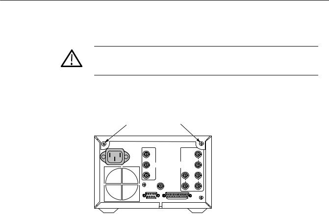
Do not attempt to carry a cabinetized instrument without installing the mounting screws. Without the mounting screws there is nothing to hold the instrument in the cabinet if it is tipped forward.
The instrument is secured to the cabinet by two 6-32 Pozidriver screws, located in the upper corners of the rear panel. See Figure 1-3.
Cabinet Mounting Screws
Figure 1-3: Rear view of the WFM 601i.
Rack Adapter The optional 1700F05 side-by-side rack adapter, shown in Figure 1-4, consists of two attached cabinets. It can be used to mount the WFM601i and another half-rack width instrument, such as an analog component monitor (Tektronix WFM300A or 1760-Series), in a standard 19-inch rack.
WFM 601i Serial Component Monitor |
1±9 |

Installation
18.970
 CONTROLS FRONT PANEL
TO RACK
ALIGNMENT. 
6.875
5.250
Mounting |
17.270 |
Holes |
|
|
Rear View |
Figure 1-4: The 1700F05 side-by-side rack adapter.
The rack adapter is adjustable, so that the WFM 601i can be more closely aligned with other equipment in the rack. See Figure 1-4.
1700F05
1700F06
Figure 1-5: Instrument in 1700F05 with blank front-panel (1700F06).
1±10 |
Rev May 1994 |
WFM 601i Serial Component Monitor |

Installation
If only one side of the rack adapter is used, a 1700F06 Blank Panel can be inserted in the unused section. See Figure 1-5. The rack adapter and panel are available through your local Tektronix field office or representative.
When only one instrument is mounted in the side-by-side adaptor an accessory drawer (1700F07) can be installed in the blank side of the cabinet. See Figure 1-6.
1700F05
1700F07
Figure 1-6: 1700F05 cabinet with 1700F07 utility drawer.
Custom Installation For applications such as consoles the instrument can be mounted with the front molding flush or protruding from the console. In both cases, allow approximately 3 inches of rear clearance for BNC and power-cord connections.
WFM 601i Serial Component Monitor |
1±11 |

Installation
To mount the WFM601i safely, attach it to a shelf strong enough to hold its weight. Install the mounting screws through the four 0.156-inch diameter holes in the bottom of the 1700F00 cabinet. See Figure 1-7.
For Flush Front Panel: Cut hole the same size as the monitor front molding to allow the monitor front panel to align with the custom panel surface.
Requires four 0.156º holes below the 1700F00 cabinet to secure the instrument to the shelf.
For Protruding Front Molding: Cut hole in panel the same size as the opening in the monitor cabinet to allow the front panel molding to cover the hole.
Figure 1-7: Custom installation considerations.
1±12 |
WFM 601i Serial Component Monitor |
 Loading...