


Service Manual
THS 710 & THS 720
TekScope
070-9246-03
This document applies to firmware version 1.00 and above.
Warning
The servicing instructions are for use by qualified personnel only. To avoid personal injury, do not perform any servicing unless you are qualified to do so. Refer to all safety summaries prior to performing service.
Copyright E Tektronix, Inc. 1995. All rights reserved.
Tektronix products are covered by U.S. and foreign patents, issued and pending. Information in this publication supercedes that in all previously published material. Specifications and price change privileges reserved.
Printed in the U.S.A.
Tektronix, Inc., P.O. Box 1000, Wilsonville, OR 97070±1000
TEKTRONIX and TEK are registered trademarks of Tektronix, Inc.
Tek Secure is a registered trademark of Tektronix, Inc.
TekTools, TekScope, and IsolatedChannel are trademarks of Tektronix, Inc.
WARRANTY
Tektronix warrants that this product will be free from defects in materials and workmanship for a period of three (3) years from the date of shipment. If any such product proves defective during this warranty period, Tektronix, at its option, either will repair the defective product without charge for parts and labor, or will provide a replacement in exchange for the defective product.
In order to obtain service under this warranty, Customer must notify Tektronix of the defect before the expiration of the warranty period and make suitable arrangements for the performance of service. Customer shall be responsible for packaging and shipping the defective product to the service center designated by Tektronix, with shipping charges prepaid. Tektronix shall pay for the return of the product to Customer if the shipment is to a location within the country in which the Tektronix service center is located. Customer shall be responsible for paying all shipping charges, duties, taxes, and any other charges for products returned to any other locations.
This warranty shall not apply to any defect, failure or damage caused by improper use or improper or inadequate maintenance and care. Tektronix shall not be obligated to furnish service under this warranty a) to repair damage resulting from attempts by personnel other than Tektronix representatives to install, repair or service the product; b) to repair damage resulting from improper use or connection to incompatible equipment; or c) to service a product that has been modified or integrated with other products when the effect of such modification or integration increases the time or difficulty of servicing the product.
THIS WARRANTY IS GIVEN BY TEKTRONIX WITH RESPECT TO THIS PRODUCT IN LIEU OF ANY OTHER WARRANTIES, EXPRESSED OR IMPLIED. TEKTRONIX AND ITS VENDORS DISCLAIM ANY IMPLIED WARRANTIES OF MERCHANTABILITY OR FITNESS FOR A PARTICULAR PURPOSE.
TEKTRONIX' RESPONSIBILITY TO REPAIR OR REPLACE DEFECTIVE PRODUCTS IS THE SOLE AND EXCLUSIVE REMEDY PROVIDED TO THE CUSTOMER FOR BREACH OF THIS WARRANTY. TEKTRONIX AND ITS VENDORS WILL NOT BE LIABLE FOR ANY INDIRECT, SPECIAL, INCIDENTAL, OR CONSEQUENTIAL DAMAGES IRRESPECTIVE OF WHETHER TEKTRONIX OR THE VENDOR HAS ADVANCE NOTICE OF THE POSSIBILITY OF SUCH DAMAGES.
Service Assurance
If you have not already purchased Service Assurance for this product, you may do so at any time during the product's warranty period. Service Assurance provides Repair Protection and Calibration Services to meet your needs.
Repair Protection extends priority repair services beyond the product's warranty period; you may purchase up to three years of Repair Protection.
Calibration Services provide annual calibration of your product, standards compliance and required audit documentation, recall assurance, and reminder notification of scheduled calibration. Coverage begins upon registration; you may purchase up to five years of Calibration Services.
Service Assurance Advantages
HPriced well below the cost of a single repair or calibration
HAvoid delays for service by eliminating the need for separate purchase authorizations from your company
HEliminates unexpected service expenses
For Information and Ordering
For more information or to order Service Assurance, contact your Tektronix representative and provide the information below. Service Assurance may not be available in locations outside the United States of America.
Name |
VISA or Master Card number and expiration |
Company |
date or purchase order number |
Address |
Repair Protection (1,2, or 3 years) |
City, State, Postal code |
Calibration Services (1,2,3,4, or 5 years) |
Country |
Instrument model and serial number |
Phone |
Instrument purchase date |

Table of Contents
General Safety Summary . . . . . . . . . . . . . . . . . . . . . . . . . . . . . . . . . . . . |
v |
Service Safety Summary . . . . . . . . . . . . . . . . . . . . . . . . . . . . . . . . . . . . . |
vii |
Preface . . . . . . . . . . . . . . . . . . . . . . . . . . . . . . . . . . . . . . . . . . . . . . . . . . . |
ix |
Related Manuals . . . . . . . . . . . . . . . . . . . . . . . . . . . . . . . . . . . . . . . . . . . . . . . . . . |
ix |
Conventions . . . . . . . . . . . . . . . . . . . . . . . . . . . . . . . . . . . . . . . . . . . . . . . . . . . . . |
x |
Specifications |
|
Specifications . . . . . . . . . . . . . . . . . . . . . . . . . . . . . . . . . . . . . . . . . . . . . . |
1±1 |
Operator Information |
|
Internal and External Power Sources . . . . . . . . . . . . . . . . . . . . . . . . . . . . . . . . . . |
2±1 |
Understanding the Front Panel . . . . . . . . . . . . . . . . . . . . . . . . . . . . . . . . . . . . . . . |
2±3 |
Connecting and Using the Probes . . . . . . . . . . . . . . . . . . . . . . . . . . . . . . . . . . . . |
2±7 |
Theory of Operation |
|
Main Board . . . . . . . . . . . . . . . . . . . . . . . . . . . . . . . . . . . . . . . . . . . . . . . . . . . . . . |
3±1 |
Inverter Board . . . . . . . . . . . . . . . . . . . . . . . . . . . . . . . . . . . . . . . . . . . . . . . . . . . |
3±1 |
Display Module . . . . . . . . . . . . . . . . . . . . . . . . . . . . . . . . . . . . . . . . . . . . . . . . . . |
3±2 |
Switch Assembly . . . . . . . . . . . . . . . . . . . . . . . . . . . . . . . . . . . . . . . . . . . . . . . . . |
3±2 |
Performance Verification |
|
Test Record . . . . . . . . . . . . . . . . . . . . . . . . . . . . . . . . . . . . . . . . . . . . . . . . . . . . . . |
4±2 |
Performance Verification Procedures . . . . . . . . . . . . . . . . . . . . . . . . . . . . . . . . . . |
4±4 |
Adjustment Procedures |
|
Required Equipment . . . . . . . . . . . . . . . . . . . . . . . . . . . . . . . . . . . . . . . . . . . . . . . |
5±1 |
Overview of the Adjustment Process . . . . . . . . . . . . . . . . . . . . . . . . . . . . . . . . . . |
5±2 |
Accessing the Adjustment-Lockout Jumper . . . . . . . . . . . . . . . . . . . . . . . . . . . . |
5±3 |
Oscilloscope Adjustment . . . . . . . . . . . . . . . . . . . . . . . . . . . . . . . . . . . . . . . . . . . |
5±5 |
Meter Adjustment . . . . . . . . . . . . . . . . . . . . . . . . . . . . . . . . . . . . . . . . . . . . . . . . . |
5±8 |
Replacing the Adjustment-Lockout Jumper . . . . . . . . . . . . . . . . . . . . . . . . . . . . . |
5±11 |
Maintenance |
|
Preparation . . . . . . . . . . . . . . . . . . . . . . . . . . . . . . . . . . . . . . . . . . . . . . . . . . . . . . |
6±1 |
Preventing ESD . . . . . . . . . . . . . . . . . . . . . . . . . . . . . . . . . . . . . . . . . . . . . . . . . . |
6±1 |
Inspection and Cleaning . . . . . . . . . . . . . . . . . . . . . . . . . . . . . . . . . . . . . . . . . . . . |
6±2 |
Removal and Installation Procedures . . . . . . . . . . . . . . . . . . . . . . . . . . . . . . . . . . |
6±5 |
Troubleshooting . . . . . . . . . . . . . . . . . . . . . . . . . . . . . . . . . . . . . . . . . . . . . . . . . . |
6±28 |
Repackaging Instructions . . . . . . . . . . . . . . . . . . . . . . . . . . . . . . . . . . . . . . . . . . . |
6±40 |
THS 710 & THS 720 Service Manual |
i |

Contents
Options
Options . . . . . . . . . . . . . . . . . . . . . . . . . . . . . . . . . . . . . . . . . . . . . . . . . . . |
7±1 |
Electrical Parts List |
|
Electrical Parts List . . . . . . . . . . . . . . . . . . . . . . . . . . . . . . . . . . . . . . . . . |
8±1 |
Diagrams |
|
Diagrams . . . . . . . . . . . . . . . . . . . . . . . . . . . . . . . . . . . . . . . . . . . . . . . . . |
9±1 |
Mechanical Parts List |
|
Parts Ordering Information . . . . . . . . . . . . . . . . . . . . . . . . . . . . . . . . . . . . . . . . . |
10±1 |
Using the Replaceable Parts List . . . . . . . . . . . . . . . . . . . . . . . . . . . . . . . . . . . . . |
10±2 |
ii |
THS 710 & THS 720 Service Manual |

Contents
List of Figures
Figure 3±1: Module-level block diagram . . . . . . . . . . . . . . . . . . . . . . . |
3±2 |
Figure 5±1: Location of adjustment-lockout jumper . . . . . . . . . . . . . . |
5±4 |
Figure 5±2: Oscilloscope adjustment setups . . . . . . . . . . . . . . . . . . . . . |
5±6 |
Figure 5±3: Meter adjustment setups . . . . . . . . . . . . . . . . . . . . . . . . . . |
5±9 |
Figure 5±4: Relocating the adjustment-lockout jumper . . . . . . . . . . . |
5±11 |
Figure 6±1: Removing the tilt stand . . . . . . . . . . . . . . . . . . . . . . . . . . . |
6±8 |
Figure 6±2: Installing the tilt stand . . . . . . . . . . . . . . . . . . . . . . . . . . . . |
6±9 |
Figure 6±3: Installing a new front-panel label . . . . . . . . . . . . . . . . . . . |
6±10 |
Figure 6±4: Removing the battery door . . . . . . . . . . . . . . . . . . . . . . . . |
6±12 |
Figure 6±5: Assembling a new front cover . . . . . . . . . . . . . . . . . . . . . . |
6±13 |
Figure 6±6: Installing the gasket . . . . . . . . . . . . . . . . . . . . . . . . . . . . . . |
6±14 |
Figure 6±7: Installing the handle . . . . . . . . . . . . . . . . . . . . . . . . . . . . . . |
6±15 |
Figure 6±8: Removing the display module . . . . . . . . . . . . . . . . . . . . . . |
6±17 |
Figure 6±9: Opening the display cable connector . . . . . . . . . . . . . . . . |
6±18 |
Figure 6±10: Routing cables to the inverter board . . . . . . . . . . . . . . . |
6±19 |
Figure 6±11: Lifting the chassis . . . . . . . . . . . . . . . . . . . . . . . . . . . . . . . |
6±20 |
Figure 6±12: Foam pad and hole plug locations on the |
|
back cover . . . . . . . . . . . . . . . . . . . . . . . . . . . . . . . . . . . . . . . . . . . . . |
6±21 |
Figure 6±13: Routing the battery wires . . . . . . . . . . . . . . . . . . . . . . . . . |
6±22 |
Figure 6±14: Removing the main board and switch |
|
flex-circuit assembly . . . . . . . . . . . . . . . . . . . . . . . . . . . . . . . . . . . . . |
6±24 |
Figure 6±15: Foam pad locations on the chassis . . . . . . . . . . . . . . . . . . |
6±25 |
Figure 6±16: Reassembling the chassis . . . . . . . . . . . . . . . . . . . . . . . . . |
6±27 |
Figure 6±17: Battery connector location . . . . . . . . . . . . . . . . . . . . . . . . |
6±29 |
Figure 6±18: Bypassing the ON/STBY switch . . . . . . . . . . . . . . . . . . . |
6±31 |
Figure 10±1: Exploded diagram . . . . . . . . . . . . . . . . . . . . . . . . . . . . . . . |
10±5 |
THS 710 & THS 720 Service Manual |
iii |

Contents
List of Tables
Table 1±1: Oscilloscope specifications . . . . . . . . . . . . . . . . . . . . . . . . . |
1±1 |
Table 1±2: DMM specifications . . . . . . . . . . . . . . . . . . . . . . . . . . . . . . . |
1±6 |
Table 1±3: General specifications . . . . . . . . . . . . . . . . . . . . . . . . . . . . . |
1±8 |
Table 5±1: Summary of oscilloscope adjustment steps . . . . . . . . . . . . |
5±5 |
Table 5±2: Summary of meter adjustment steps . . . . . . . . . . . . . . . . . |
5±8 |
Table 6±1: Internal inspection check list . . . . . . . . . . . . . . . . . . . . . . . |
6±3 |
Table 6±2: Removal and installation procedures . . . . . . . . . . . . . . . . . |
6±6 |
Table 7±1: TekScope instrument options . . . . . . . . . . . . . . . . . . . . . . . |
7±1 |
Table 10±1: Replaceable standard accessories . . . . . . . . . . . . . . . . . . . |
10±6 |
iv |
THS 710 & THS 720 Service Manual |

General Safety Summary
|
Review the following safety precautions to avoid injury and prevent damage to |
|
this product or any products connected to it. |
|
Only qualified personnel should perform service procedures. |
Injury Precautions |
|
Avoid Electric Overload |
To avoid injury or fire hazard, do not apply a voltage to any input, including the |
|
common inputs, that varies from ground by more than the maximum rating for |
|
that input. |
Avoid Electric Shock |
To avoid injury or loss of life, do not connect or disconnect probes or test leads |
|
while they are connected to a voltage source. |
Do Not Operate Without |
To avoid electric shock or fire hazard, do not operate this product with covers or |
Covers |
panels removed. |
Do Not Operate in |
To avoid electric shock, do not operate this product in wet or damp conditions. |
Wet/Damp Conditions |
|
Do Not Operate in |
To avoid injury or fire hazard, do not operate this product in an explosive |
Explosive Atmosphere |
atmosphere. |
Product Damage Precautions
Use Proper Power Source Do not operate this product from a power source that applies more than the voltage specified.
Do Not Operate With |
If you suspect there is damage to this product, have it inspected by qualified |
Suspected Failures |
service personnel. |
THS 710 & THS 720 Service Manual |
v |

General Safety Summary
Safety Terms and Symbols
Terms in This Manual These terms may appear in this manual:
WARNING. Warning statements identify conditions or practices that could result in injury or loss of life.
CAUTION. Caution statements identify conditions or practices that could result in damage to this product or other property.
Terms on the Product These terms may appear on the product:
DANGER indicates an injury hazard immediately accessible as you read the marking.
WARNING indicates an injury hazard not immediately accessible as you read the marking.
CAUTION indicates a hazard to property including the product.
Symbols on the Product The following symbols may appear on the product:
DANGER |
Protective Ground |
ATTENTION |
Double |
High Voltage |
(Earth) Terminal |
Refer to Manual |
Insulated |
Certifications and Compliances
CSA Certified AC Adapter CSA Certification includes the AC adapters appropriate for use in the North America power network. All other AC adapters supplied are approved for the country of use.
Compliances Consult the product specifications for Installation Category, Pollution Degree, and Safety Class.
vi |
THS 710 & THS 720 Service Manual |
Service Safety Summary
Only qualified personnel should perform service procedures. Read this Service
Safety Summary and the General Safety Summary before performing any service procedures.
Do Not Service Alone Do not perform internal service or adjustments of this product unless another person capable of rendering first aid and resuscitation is present.
Use Care When Servicing Dangerous voltages or currents may exist in this product. Disconnect power, With Power On remove battery (if applicable), and disconnect test leads before removing
protective panels, soldering, or replacing components.
To avoid electric shock, do not touch exposed connections.
THS 710 & THS 720 Service Manual |
vii |

Service Safety Summary
viii |
THS 710 & THS 720 Service Manual |

Preface
This is the Service Manual for the THS 700 Series TekScope instruments. This manual provides information to troubleshoot and repair the instrument to the module level.
Related Manuals
Additional documentation for the instrument is contained in the related manuals listed below.
|
User Manual |
Reference |
Programmer Manual |
Language |
Part Number |
Part Number |
Part Number |
|
|
|
|
English |
070-9247-XX |
070-9257-XX |
070-9245-XX |
|
|
|
|
French |
070-9248-XX |
070-9275-XX |
|
|
|
|
|
German |
070-9249-XX |
070-9276-XX |
|
|
|
|
|
Italian |
070-9250-XX |
070-9277-XX |
|
|
|
|
|
Korean |
070-9251-XX |
070-9278-XX |
|
|
|
|
|
Portuguese |
070-9252-XX |
070-9279-XX |
|
|
|
|
|
Spanish |
070-9253-XX |
070-9280-XX |
|
|
|
|
|
Simple Chinese |
070-9254-XX |
070-9281-XX |
|
|
|
|
|
Standard |
070-9255-XX |
070-9256-XX |
|
Chinese |
|
|
|
|
|
|
|
Japanese |
070-9258-XX |
|
|
|
|
|
|
THS 710 & THS 720 Service Manual |
ix |
Preface
Conventions
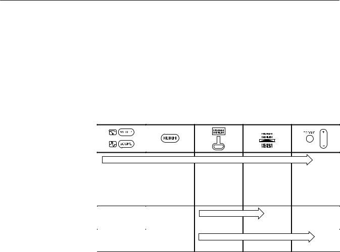
In the Performance Verification, Adjustments, and Maintenance chapters of this manual, TekScope instrument setups are shown in tables similar to the one shown below.
The header of each table contains icons that represent the controls and menu items used to set up the instrument. To make a specific setup, read the table from left to right and then from top to bottom as shown below. The table contains the symbol ªÐº if no action is required.
1. Choose scope |
2. Press this but- |
3. Press this |
mode or meter |
ton on the front |
bezel button. |
mode. |
panel. |
|
|
|
|
|
|
|
|
|
|
|
|
|
|
|
|
|
|
|
|
|
|
|
|
|
|
|
|
|
|
|
|
|
|
|
|
|
|
|
|
|
|
|
|
|
|
|
|
|
4. Press the |
5. Use the |
|||||||
bezel button |
+/± rocker to set |
|||||||
again until this |
the value for a |
|||||||
selection is high- |
parameter. |
|||||||
lighted. |
|
|
|
|
|
|
||
6. |
7. |
Ð |
8. |
9. |
10. |
x |
THS 710 & THS 720 Service Manual |

Specifications
This chapter contains the oscilloscope, DMM, and general specifications for the THS 710 and THS 720 TekScope instruments. All specifications are guaranteed unless noted ªtypical.º Specifications that are marked with the n symbol are checked in the chapter Performance Verification.
All specifications apply to both the THS 710 and THS 720 unless noted otherwise. All specifications assume horizontal MAG is off, unless noted otherwise. To meet specifications, two conditions must first be met:
HThe TekScope instrument must have been operating continuously for ten minutes within the operating temperature range specified.
HYou must perform the Compensate Signal Path operation, accessible through the utility menu, if the ambient temperature changes by more than 5° C.
Table 1±1: Oscilloscope specifications
Acquisition
Acquisition Modes |
Sample (Normal), Peak detect, Envelope, and Average |
||
|
|
|
|
Acquisition Rate, |
Up to 25 waveforms per second (2 channels, sample acquisition mode, |
||
typical |
MAG on, no measurements) |
|
|
|
|
|
|
Single Sequence |
Acquisition Mode |
Acquisition Stops After |
|
|
|
|
|
|
Sample, Peak Detect |
Single acquisition, one or two |
|
|
|
channels simultaneously |
|
|
|
|
|
|
Average, Envelope |
N acquisitions, one or two chan- |
|
|
|
nels simultaneously, N is settable |
|
|
|
from 2 to 256 or ∞ |
|
Inputs |
|
|
|
|
|
|
|
Input Coupling |
DC, AC, or GND |
|
|
|
|
||
Input Impedance, |
1 M ±1% in parallel with 25 pF ±2 pF |
||
DC Coupled |
|
|
|
|
|
|
|
Maximum Voltage |
Overvoltage Category |
Maximum Voltage |
|
Between Signal and |
|
|
|
CAT II Environment |
300 VRMS |
||
Common at Input |
|||
CAT III Environment |
150 VRMS |
||
BNC |
|||
|
For steady-state sinusoidal waveforms, derate at 20 dB/decade above |
||
|
100 kHz to 13 Vpk at 3 MHz and above. Also, refer to Overvoltage |
||
|
Category description on page 1±10. |
|
|
Maximum Voltage |
30 VRMS, 42.4 Vpk |
|
|
Between Common |
|
|
|
and Earth Ground |
|
|
|
at BNC |
|
|
|
THS 710 & THS 720 Service Manual |
1±1 |

Specifications
Table 1±1: Oscilloscope specifications (Cont.)
Inputs
Channel-to-Channel |
100:1 at frequencies ≤50 MHz, measured on MATH Ch1 ± Ch2 |
||
Common Mode |
waveform, with test signal applied between signal and common of both |
||
Rejection, typical |
channels, and with the same VOLTS/DIV and coupling settings on each |
||
|
channel |
|
|
Channel-to-Channel |
≥ 100:1 at 50 MHz, measured on one channel, with test signal applied |
||
Crosstalk, typical |
between signal and common of the other channel, and with the same |
||
|
VOLTS/DIV and coupling settings on each channel |
||
|
|
|
|
Common to Chassis |
65 pF |
|
|
Capacitance, typical |
|
|
|
|
|
|
|
Vertical |
|
|
|
|
|
|
|
Number of Channels |
2 |
|
|
|
|
|
|
Digitizers |
8 bit resolution, separate digitizers for each channel sample |
||
|
simultaneously |
|
|
|
|
|
|
VOLTS/DIV Range |
5 mV/div to 50 V/div at input BNC |
|
|
|
|
|
|
Polarity |
Normal and Invert |
|
|
|
|
|
|
Position Range |
±10 divisions |
|
|
nAnalog Bandwidth |
THS 710 |
THS 720 |
|
at BNC, DC Coupled |
|
|
|
60 MHz at input BNC |
100 MHz at input BNC |
||
(at 5 mV/div, typical) |
|||
|
(90 MHz above 35° C) |
||
|
|
||
Peak Detect or Enve- |
THS 710 |
THS 720 |
|
lope Bandwidth, |
|
|
|
50 MHz (1 ms/div or slower) |
75 MHz (1 ms/div or slower) |
||
typical |
|||
|
|
|
|
Analog Bandwidth |
Selectable between 20 MHz or full |
|
|
Limit, typical |
|
|
|
|
|
||
Lower Frequency |
≤10 Hz at BNC, reduced by a factor of ten when using a 10X passive |
||
Limit, AC Coupled, |
probe |
|
|
typical |
|
|
|
|
|
|
|
Rise Time at BNC, |
THS 710 |
THS 720 |
|
typical |
|
|
|
5.8 ns |
3.5 ns |
||
|
|||
|
|
|
|
Peak Detect or Enve- |
Captures 50% or greater amplitude of pulses ≥ 8 ns wide (≥ 20 ns wide |
||
lope Pulse Response, |
at 500 ns/div) |
|
|
typical |
|
|
|
|
|
||
DC Gain Accuracy |
±2% for Sample or Average acquisition mode |
||
Position Accuracy |
±[0.4% ×|(position ×volts/div)| + (0.1 div ×volts/div)] |
||
1±2 |
THS 710 & THS 720 Service Manual |

Specifications
Table 1±1: Oscilloscope specifications (Cont.)
Vertical
nDC Measurement |
Measurement Type |
Accuracy |
|
Accuracy, Average |
Average of ≥ 16 waveforms |
±[2% ×|reading + |
|
Acquisition Mode |
|||
|
(position ×volts/div)| + |
||
|
|
||
|
|
(0.1 div ×volts/div)] |
|
|
Delta volts between any two |
±[2% ×|reading| + |
|
|
averages of ≥ 16 waveforms |
(0.05 div ×volts/div)] |
|
|
acquired under same setup and |
|
|
|
ambient conditions |
|
|
DC Measurement |
±[2% ×|reading + (position ×volts/div)| + (0.15 div ×volts/div) + |
||
Accuracy, Sample |
0.6 mV] |
|
|
Acq. Mode, typical |
|
|
|
|
|
|
|
Horizontal |
|
|
|
|
|
|
|
Sample Rate Range |
THS 710 |
THS 720 |
|
|
|
|
|
|
5 S/s to 250 MS/s, in a 1.25, 2.5, |
5 S/s to 500 MS/s, in a 1.25, 2.5, |
|
|
5 sequence |
5 sequence |
|
|
|
|
|
Record Length |
2500 samples for each channel |
|
|
|
|
|
|
SEC/DIV Range |
THS 710 |
THS 720 |
|
(including MAG) |
|
|
|
10 ns/div to 50 s/div |
5 ns/div to 50 s/div |
||
|
|||
|
|
|
|
nSample Rate and |
±200 ppm over any ≥ 1 ms time interval |
||
Delay Time Accuracy |
|
|
|
|
|
|
|
Delay Time Range |
Zero to 50 s |
|
|
|
|
|
|
Trigger |
|
|
|
|
|
|
|
n Trigger Sensitivity, |
Coupling |
Sensitivity |
|
Edge Trigger Type |
|
|
|
DC |
0.35 div from DC to 50 MHz, |
||
|
|||
|
|
increasing to 1 div at 100 MHz |
|
|
|
|
|
Trigger Sensitivity, |
Coupling |
Sensitivity |
|
Edge Trigger Type, |
|
|
|
NOISE REJ |
3.5 times the DC-coupled limits |
||
typical |
|||
|
|
||
HF REJ |
1.5 times the DC-coupled limit |
||
|
|||
|
|
from DC to 30 kHz, attenuates |
|
|
|
signals above 30 kHz |
|
|
|
|
|
|
LF REJ |
1.5 times the DC-coupled limits |
|
|
|
for frequencies above 1 kHz, |
|
|
|
attenuates signals below 1 kHz |
|
Trigger Level Range |
±4 divisions from center of screen |
|
|
Trigger Level |
±0.2 divisions, for signals having rise and fall times ≥ 20 ns |
||
Accuracy, typical |
|
|
|
|
|
|
|
SET LEVEL TO 50%, |
Operates with input signals ≥ 50 Hz |
|
|
typical |
|
|
|
|
|
||
Width Range, Pulse |
99 ns to 1 s, with resolution of 33 ns or approximately 1% of setting |
||
Trigger Type, typical |
(whichever is greater) |
|
|
|
|
|
|
THS 710 & THS 720 Service Manual |
1±3 |

Specifications
Table 1±1: Oscilloscope specifications (Cont.)
Trigger
Width Tolerance |
5%, 10%, 15%, or 20% |
|
|
Range, Pulse Trigger |
|
|
|
Type, typical |
|
|
|
Sensitivity, Video |
Composite video signal with negative sync pulse amplitude from 0.6 |
||
Trigger Type, typical |
to 2.5 divisions |
|
|
|
|
|
|
Signal Formats and |
Broadcast systems |
Supports NTSC, PAL, and |
|
Field Rates, Video |
|
SECAM |
|
Trigger Type |
|
|
|
Interlaced |
Field 1 or field 2 |
||
|
|||
|
|
|
|
|
Non-interlaced |
Any field or any line |
|
|
|
|
|
|
Line Rates |
15 kHz to 65 kHz, in five ranges |
|
|
|
|
|
Holdoff Range |
495 ns to 10 s |
|
|
|
|
|
|
Measurements |
|
|
|
|
|
||
Cursors |
Voltage difference between cursors (DV) |
||
|
Time difference between cursors (DT) |
||
|
Reciprocal of DT in Hertz (1/DT) |
|
|
|
|
||
Automated |
Amplitude, Burst Width, Cycle Mean, Cycle RMS, Fall Time, |
||
Measurements |
Frequency, High, Low, Max, Mean, Min, Negative Duty Cycle, Negative |
||
|
Overshoot, Negative Width, Pk ± Pk, Period, Positive Duty Cycle, |
||
|
Positive Overshoot, Positive Width, Rise Time, and RMS |
||
|
|
|
|
With P6113B Probe |
|
|
|
|
|
|
|
Analog Bandwidth, |
THS 710 |
THS 720 |
|
DC Coupled |
|
|
|
60 MHz |
100 MHz |
||
|
|||
|
|
|
|
Probe Attenuation |
10X |
|
|
|
|
|
|
Maximum Voltage |
Overvoltage Category |
Maximum Voltage |
|
Between Probe Tip |
|
|
|
CAT II Environment |
300 VRMS |
||
and Reference Lead |
|||
CAT III Environment |
150 VRMS |
||
|
|||
|
For steady-state sinusoidal waveforms, derate at 20 dB/decade above |
||
|
100 kHz to 13 Vpk at 3 MHz and above. Also, refer to Overvoltage |
||
|
Category description on page 1±10. |
|
|
Maximum Voltage |
30 VRMS, 42.4 Vpk |
|
|
Between Reference |
|
|
|
Lead and Earth |
|
|
|
Ground Using |
|
|
|
P6113B Probe |
|
|
|
1±4 |
THS 710 & THS 720 Service Manual |

Specifications
Table 1±1: Oscilloscope specifications (Cont.)
With P5102 Probe
Analog Bandwidth, |
THS 710 |
THS 720 |
|
DC Coupled |
|
|
|
60 MHz |
100 MHz |
||
|
|||
|
|
|
|
Probe Attenuation |
10X |
|
|
|
|
|
|
Maximum Voltage |
Overvoltage Category |
Maximum Voltage |
|
Between Probe Tip |
|
|
|
CAT II Environment |
1000 VRMS |
||
and Reference Lead, |
|||
DC Coupled |
CAT III Environment |
600 VRMS |
|
Maximum Voltage |
Overvoltage Category |
Maximum Voltage |
|
Between Probe Tip |
|
|
|
CAT II Environment |
±1000 VDC |
||
and Reference Lead, |
|||
AC Coupled |
CAT III Environment |
±600 VDC |
|
Maximum Voltage |
Overvoltage Category |
Maximum Voltage |
|
Between Reference |
|
|
|
CAT II Environment |
600 VRMS |
||
Lead and Earth |
|||
Ground |
CAT III Environment |
300 VRMS |
|
Single Channel Com- |
1000:1 from DC to 100 kHz, measured on either channel, with probe tip |
||
mon Lead Feed- |
and reference lead connected together, and with test signal applied |
||
through with P5102 |
between tip/reference and earth ground |
||
Probe, typical |
A 3000 V/ms slew rate results in ≤0.5 division feedthrough, measured |
||
|
|||
|
on either channel, with probe tip and reference lead connected |
||
|
together, and with test signal applied between tip/reference and earth |
||
|
ground |
|
|
|
|
|
|
THS 710 & THS 720 Service Manual |
1±5 |
Specifications
Table 1±2: DMM specifications
General
Resolution |
33⁄ digit, 4000 count full scale reading except as noted |
||
|
4 |
|
|
Input Resistance, AC |
10 M ±10% |
|
|
or DC Voltage |
|
|
|
|
|
|
|
Input Capacitance, |
≤100 pF |
|
|
AC or DC Voltage, |
|
|
|
typical |
|
|
|
Maximum Voltage |
Overvoltage Category |
Maximum Voltage |
|
Between DMM and |
|
|
|
CAT II Environment |
600 VRMS |
||
COM Inputs |
|||
CAT III Environment |
300 VRMS |
||
|
|||
Maximum Voltage |
Overvoltage Category |
Maximum Voltage |
|
Between DMM or |
|
|
|
CAT II Environment |
600 VRMS |
||
COM Input and Earth |
|||
Ground |
CAT III Environment |
300 VRMS |
|
DC Voltage |
|
|
|
|
|
|
|
Ranges and |
Range |
Resolution |
|
Resolution |
|
|
|
400.0 mV |
0.1 mV |
||
|
|||
|
|
|
|
|
4.000 V |
1 mV |
|
|
|
|
|
|
40.00 V |
10 mV |
|
|
|
|
|
|
400.0 V |
100 mV |
|
|
|
|
|
|
880 V |
1 V |
|
|
|
|
|
nAccuracy |
±(0.5% of reading + 5 counts) |
|
|
Normal Mode |
Rejects AC signals by >60 dB at 50 Hz or 60 Hz (user selectable) |
||
Rejection, typical |
|
|
|
|
|
||
Common Mode |
Rejects AC signals by >100 dB at 50 Hz or 60 Hz (user selectable) |
||
Rejection, typical |
|
|
|
|
|
|
|
AC Voltage |
|
|
|
|
|
||
Conversion Type |
AC conversions are true RMS. The AC measurement is based on the |
||
|
AC and DC components of the signal as shown below: |
||
|
AC Measurement = RMS(AC+DC) ± DC |
||
|
|
|
|
Ranges and |
Range |
Resolution |
|
Resolution |
|
|
|
400.0 mV |
0.1 mV |
||
|
|||
|
|
|
|
|
4.000 V |
1 mV |
|
|
|
|
|
|
40.00 V |
10 mV |
|
|
|
|
|
|
400.0 V |
100 mV |
|
|
|
|
|
|
640 V |
1 V |
|
1±6 |
THS 710 & THS 720 Service Manual |

Specifications
Table 1±2: DMM specifications (Cont.)
AC Voltage
nAccuracy |
Input Waveform |
Maximum Error |
|
|
Sinusoidal waveforms |
±(2% of reading + 5 counts) |
|
|
Nonsinusoidal waveforms with |
±(4% of reading + 5 counts) |
|
|
crest factor up to 3 |
|
|
|
|
|
|
Bandwidth, typical |
≥ 5 kHz for all ranges |
|
|
Common Mode |
Rejects AC signals by >60 dB at DC, 50 Hz, and 60 Hz |
||
Rejection, typical |
|
|
|
|
|
|
|
/Resistance |
|
|
|
|
|
|
|
Ranges and |
Range |
Resolution |
|
Resolution |
|
|
|
400.0 |
0.1 |
||
|
|||
|
|
|
|
|
4.000 k |
1 |
|
|
|
|
|
|
40.00 k |
10 |
|
|
|
|
|
|
400.0 k |
100 |
|
|
|
|
|
|
4.000 M |
1 k |
|
|
|
|
|
|
40.00 M |
10 k |
|
|
|
|
|
Accuracy, typical |
Range |
Maximum Error |
|
|
|
|
|
|
All ranges except 40 M |
±(0.5% of reading + 2 counts) |
|
|
40 M |
±(2% of reading + 5 counts) for |
|
|
|
≤60% relative humidity |
|
Bias Voltage for Full |
Range |
Full Scale Bias Voltage |
|
Scale Resistance |
|
|
|
400.0 |
350 mV |
||
Measurement, typical |
|||
|
|
||
4.000 k |
200 mV |
||
|
|||
|
|
|
|
|
40.00 k |
350 mV |
|
|
|
|
|
|
400.0 k |
350 mV |
|
|
|
|
|
|
4.000 M |
400 mV |
|
|
|
|
|
|
40.00 M |
1.10 V |
|
|
|
|
|
Open Circuit Voltage, |
Range |
Open Circuit Voltage |
|
typical |
|
|
|
400.0 |
4.8 V |
||
|
|||
|
|
|
|
|
All other ranges |
≤1.2 V |
|
THS 710 & THS 720 Service Manual |
1±7 |

Specifications
Table 1±2: DMM specifications (Cont.)
Continuity Check
Indication |
An audible tone is generated when measured resistance is below 50 , |
|
typical |
|
|
Open Circuit Voltage, |
4.8 V |
typical |
|
|
|
Test Current, typical |
1 mA |
|
|
Diode Check |
|
|
|
Range |
Zero to 2 V, measures forward voltage drop of semiconductor junction |
|
|
Voltage Accuracy, |
±25% |
typical |
|
|
|
Open Circuit Voltage, |
4.8 V |
typical |
|
|
|
Test Current, typical |
1 mA |
|
|
Data Logger |
|
|
|
Horizontal Scale |
24 hours/div to 30 s/div (4 minutes to 8 days, full scale) |
Range |
|
|
|
Table 1±3: General specifications
Display
Display Type |
4.7 in (120 mm) diagonal liquid crystal |
||
|
|
|
|
Display Resolution |
320 horizontal by 240 vertical pixels |
|
|
|
|
|
|
Display Contrast |
Adjustable, temperature compensated |
||
|
|
|
|
Backlight Intensity, |
35 cd/m2 |
|
|
typical |
|
|
|
|
|
|
|
RS-232 Interface |
|
|
|
|
|
|
|
Device Type |
DTE |
|
|
|
|
|
|
RJ-45 Connector |
Pin Number |
Signal |
|
Pinout |
|
|
|
1 |
DCD |
||
|
|||
|
|
|
|
|
2 |
DSR |
|
|
|
|
|
|
3 |
DTR |
|
|
|
|
|
|
4 |
GND |
|
|
|
|
|
|
5 |
RXD |
|
|
|
|
|
|
6 |
TXD |
|
|
|
|
|
|
7 |
CTS |
|
|
|
|
|
|
8 |
RTS |
|
1±8 |
THS 710 & THS 720 Service Manual |

Specifications
Table 1±3: General specifications (Cont.)
Probe Compensator Output
Output Voltage, |
5.0 V into ≥ 1 M load |
|
typical |
|
|
|
|
|
Frequency, typical |
1.2 kHz |
|
|
|
|
Power Source |
|
|
|
|
|
Battery |
Replaceable Ni-Cd battery pack |
|
|
|
|
Battery Life, typical |
Approximately two hours of continuous use from a full charge |
|
|
|
|
Low Battery Indica- |
Low battery message first appears approximately ten minutes before |
|
tion, typical |
the instrument powers off automatically |
|
|
|
|
Battery Saver |
Standby Time-out and Backlight Time-out extend battery life. Time-out |
|
|
ranges from 1 minute to 15 minutes, or off. |
|
|
|
|
Battery Charging |
With TekScope instrument operat- |
20 hours |
Time, typical |
ing |
|
|
|
|
|
With TekScope instrument turned |
20 hours |
|
off |
|
|
|
|
|
In external charger |
1.5 hours |
|
|
|
External Power |
12 VDC nominal, center positive; Operates with input from 10 VDC to |
|
|
15 VDC |
|
|
The DC INPUT disconnects itself automatically if >15 VDC is applied. |
|
|
If this occurs, disconnect the overvoltage and then reconnect to a |
|
|
voltage in the proper range. |
|
Memory Retention, |
All memory is retained indefinitely with battery removed and without |
|
typical |
external power applied. |
|
|
|
|
Fuse |
This instrument has no user-replaceable fuses |
|
|
|
|
Environmental |
|
|
|
|
|
Temperature |
Operating |
±10° C to +50° C |
|
Nonoperating |
±20° C to +60° C |
|
|
|
Humidity |
+40° C or below |
≤95% relative humidity |
|
+41° C to +50° C |
≤75% relative humudity |
Altitude |
Operating |
2,000 m |
|
|
|
|
Nonoperating |
15,000 m |
|
|
|
THS 710 & THS 720 Service Manual |
1±9 |

Specifications
Table 1±3: General specifications (Cont.)
Environmental
Random Vibration |
Operating |
2.66 gRMS from 5 Hz to 500 Hz, |
|
|
10 minutes on each axis |
|
|
|
|
Nonoperating |
3.48 gRMS from 5 Hz to 500 Hz, |
|
|
10 minutes on each axis |
Drop Resistance, |
Survives a 30 in drop onto concrete with only cosmetic damage |
|
typical |
|
|
|
|
|
Mechanical |
|
|
|
|
|
Size |
Height |
8.53 in (217 mm) |
|
|
|
|
Width |
6.95 in (177 mm) |
|
|
|
|
Depth |
2.00 in (50.8 mm) |
|
|
|
Weight |
With battery installed |
3.2 lbs (1.5 kg) |
|
|
|
|
With all standard accessories in |
7.5 lbs (3.4 kg) |
|
soft carry case |
|
|
|
|
|
When packaged for domestic |
9.0 lbs (4.1 kg) |
|
shipment |
|
|
|
|
Certifications and Compliances |
|
|
|
|
|
Certifications |
Listed UL3111-1 and CAN/CSA-C22.2 No. 1010.1-92, complies with |
|
|
EN61010-1 |
|
|
|
|
Overvoltage Category |
Category |
Examples |
|
|
|
|
CAT III |
A typical CAT III environment is |
|
|
the power distribution system |
|
|
within a building or factory. These |
|
|
environments are somewhat |
|
|
protected from lightning strikes, |
|
|
but susceptible to switching |
|
|
transients and other disturbances |
|
|
that may generate high voltage |
|
|
impulses. |
|
|
|
|
CAT II |
A typical CAT II environment is |
|
|
the 120/240 V distribution system |
|
|
within a lab or office. These |
|
|
environments are fairly well |
|
|
protected from external high |
|
|
voltage disturbances. |
|
|
|
1±10 |
THS 710 & THS 720 Service Manual |

Specifications
Table 1±3: General specifications (Cont.)
Certifications and Compliances
EC Declaration of |
Meets the intent of Directive 89/336/EEC for Electromagnetic |
||
Conformity |
Compatibility and Low-Voltage Directive 73/23/ECC for Product Safety. |
||
|
Compliance was demonstrated to the following specifications as listed |
||
|
in the official Journal of the European Communities: |
||
|
EN 55011 Class A: |
Radiated and Conducted Emissions1 3 |
|
|
EN 50081±1 Emissions: |
|
|
|
|
EN 60555±2 |
Power Harmonics |
|
EN 50082±1 Immunity: |
|
|
|
|
IEC 801±2 |
Electrostatic Discharge |
|
|
IEC 801±3 |
RF Radiated2 |
|
|
IEC 801±4 |
Fast Transients |
|
|
IEC 801±5 |
Surge3 |
|
EN 61010±1 Safety |
|
|
|
1 |
Tektronix-supplied ferrite bead required on instrument end of |
|
|
|
RS-232 cable |
|
|
2 |
Performance criteria: ≤ 5.0 div increase in peak to peak noise |
|
|
|
(Sample acquisition mode, full bandwidth); otherwise, ≤ 1.0 div |
|
|
|
increase in peak to peak noise |
|
|
3 |
Applies to instrument operating with Tektronix-supplied AC |
|
|
|
adapter |
|
|
|
||
FCC Compliance |
Emissions comply with FCC Code of Federal Regulations 47 CFR, Part |
||
|
15, Subpart B, Class A |
|
|
|
|
|
|
Adjustment Interval |
|
|
|
|
|
||
The recommended adjustment interval is one year |
|
||
|
|
|
|
THS 710 & THS 720 Service Manual |
1±11 |

Specifications
1±12 |
THS 710 & THS 720 Service Manual |

Operator Information
This chapter provides a quick overview of the following topics:
HInternal and external power sources
HUnderstanding the front panel
HConnecting and using the probes
For more detailed information about TekScope instrument operation, refer to the
THS 710 & THS 720 User Manual.
Internal and External Power Sources
You can power the TekScope instrument from the internal battery pack or from the AC adapter (both are standard accessories).
Using the Battery Pack Before using the battery for the first time, it must be charged. You can use external power to charge the battery pack while it is in the TekScope instrument. Or you can charge the battery pack with the optional external battery charger. Typical battery charging times are listed below.
Configuration |
Typical Charging Time |
|
|
Battery pack in TekScope instrument |
20 hours |
|
|
Battery pack in external charger |
1.5 hours |
|
|
You can remove and replace the battery pack without losing any saved information. The current setup, saved setups, saved waveforms, and saved data are stored in nonvolatile memory that does not depend on battery power.
CAUTION. To prevent loss of saved information, set the ON/STBY switch to STBY before removing the battery pack.
THS 710 & THS 720 Service Manual |
2±1 |

Operator Information
Battery pack
Using External Power For benchtop operation, you can use external power. Attach the AC adapter as shown below.
The DC INPUT disconnects itself if an overvoltage is applied. If this occurs, disconnect and then reconnect the AC adapter to resume operation from external power.
External power to DC INPUT
CAUTION. To avoid overheating, do not connect external power while the instrument is in a confined space, such as in the soft case.
2±2 |
THS 710 & THS 720 Service Manual |
 Loading...