


TPS2024B

xx
TPS2000B Series
Digital Storage Oscilloscope
ZZZ
User Manual
*P071273301*
071-2733-01


TPS2000B Series
Digital Storage Oscilloscope
ZZZ
User Manual
xx
www.tektronix.com
071-2733-01

Copyright © Tektronix. All rights reserved. Licensed software products are owned by Tektronix or its subsidiaries
or suppliers, and are protected by national copyright laws and international treaty provisions.
Tektronix products are covered by U.S. and foreign patents, issued and pending. Information in this publication
supersedes that in all previously published material. Specifications and price change privileges reserved.
TEKTRONIX and TEK are registered trademarks of Tektronix, Inc.
OpenChoice and Wavestar are registered trademarks of Tektronix, Inc.
Tektronix is an authorized licensee of the CompactFlash® trademark.
Contacting Tektronix
Tektronix, Inc.
14150 SW Karl Braun Drive
P.O. Box 5 0 0
Beaverton, OR 97077
USA
For product information, sales, service, and technical support:
In North America, call 1-800-833-9200.
Worl dwid e, visi t www.tektronix.com to find contacts in your area.

TPS2000B Series Oscilloscope
Warranty
Tektronix war
rants that the product will be free from defects in materials and workmanship for a period of three (3)
years from the date of original purchase from an authorized Tektronix distributor. If the product proves defective
during this warranty period, Tektronix, at its option, either will repair the defective product without charge for
parts and labor, or will provide a replacement in exchange for the defective product. Batteries are excluded from
this warranty. Parts, modules and replacement products used by Tektronix for warranty work may be new or
reconditioned to like new performance. All replaced parts, modules and products become the property o f Tektronix.
In order to obtain service under this warranty, Customer must notify Tektronix of the defect before the expiration
of the warranty period and make suitable arrangements for the performance of service. Customer shall be
responsib
le for packaging and shipping the defective product to the service center designated by Tektronix,
shipping charges prepaid, and with a copy of customer proof of purchase. Tektronix shall pay for the return of the
product to Customer if the shipment is to a location within the country in which the Tektronix service center is
located. Customer shall be responsible for paying all shipping charges, duties, taxes, and any other charges for
products returned to any other locations.
This warranty shall not apply to any defect, failure or damage caused by improper use or improper or inadequate
maintenance and care. Tektronix shall not be obligated to furnish service under this warranty a) to repair damage
resulting from attempts by personnel other than Tektronix representatives to install, repair or service the product;
b) to r
epair damage resulting from improper use or connection to incompatible equipment; c) to repair any damage
or malfunction caused by the use of non-Tektronix supplies; or d) to service a product that has been modified or
integrated with other products when the effect of such modification or integration increases the time or difficulty
of servicing the product.
THIS WARRANTY IS GIVEN BY TEKTRONIX WIT H RESPECT TO THE PRODUCT IN LIEU OF ANY
OTHER WARRANTIES, EXPRESS OR IMPLIED. TEKTRONIX AND ITS VENDORS DISCLAIM ANY
IMPLIED WARRANTIES OF MERCHANTABILITY OR FITNESS FOR A PARTICULAR PURPOSE.
TEKTRONIX' RESPONSIBILITY TO REPAIR OR REPLACE DEFECTIVE PRODUCTS IS THE SOLE
AN
D EXCLUSIVE REMEDY PROVIDED TO TH E CUSTOMER FOR BREACH OF THIS WARRANTY.
TEKTRONIX AND ITS VENDORS WILL NOT BE LIABLE FOR ANY INDIRECT, SPECIAL, INCIDENTAL,
OR CONSEQUENTIAL DAMAGES IRRESPECTIVE OF WHETHER TEKTRONIX OR THE VENDOR HAS
ADVANCE NOTICE OF THE POSSIBILITY OF SUCH DAMAGES.
[W16 – 15AUG04]

TPP0101 and TPP0201 Probes
Warranty
Tektroni x wa r
rants that this product will be free from defects in materials and workmanship for a period of one (1)
year from the date of shipment. If any such product proves defective during this warranty period, Tektronix, at its
option, either will repair the defective product without charge for parts and labor, or will provide a replacement
in exchange for the defective product. Parts, modules and replacement products used by Tektronix for warranty
work may be new or reconditioned to like new performance. All replaced parts, modules and products become
the property of Tektronix.
In order to obtain service under this warranty, Customer must notify Tektronix of the defect before the expiration of
the warranty period and make suitable arrangements for the performance of service. Customer shall be responsible
for packag
ing and shipping the defective product to the service center designated by Tektronix, with shipping
charges prepaid. Tektronix shall pay for the return of the product to Customer if the shipment is to a location within
the country in which the Tektronix service center is located. Customer shall be responsible for paying all shipping
charges, duties, taxes, and any other charges for products returned to any other locations.
This warranty shall not apply to any defect, failure or damage caused by improper use or improper or inadequate
maintenance and care. Tektronix shall not be obligated to furnish service under this warranty a) to repair damage
resulting from attempts by personnel other than Tektronix representatives to install, repair or service the product;
b) to repair damage resulting from improper use or connection to incompatible equipment; c) to repair any damage
or mal
function caused by the use of non-Tektronix supplies; or d) to service a product that has been modified or
integrated with other products when the effect of such modification or integration increases the time or difficulty
of servicing the product.
THIS WARRANTY IS GIVEN BY TEKTRONIX WITH RESPECT TO THE PRODUCT IN LIEU OF ANY
OTHER WARRANTIES, EXPRESS OR IMPLIED. TEKTRONIX AND ITS VENDORS DISCLAIM ANY
IMPLIED WARRANTIES OF MERCHANTABILITY OR FITNESS FOR A PARTICULAR PURPOSE.
TEKTRONIX' RESPONSIBILITY TO REPAIR OR REPLACE DEFECTIVE PRODUCTS IS THE SOLE
AND EXCLUSIVE REMEDY PROVIDED TO THE CUSTOMER FOR BREACH OF THIS WARRANTY.
TE
KTRONIX AND ITS VENDORS WILL NOT BE LIABLE FOR ANY INDIRECT, SPECIAL, INCIDENTAL,
OR CONSEQUENTIAL DAMAGES IRRESPECTIVE OF WHETHER TEKTRONIX OR THE VENDOR HAS
ADVANCE NOTICE OF THE POSSIBILITY OF SUCH DAMAGES.
[W2 – 15AUG04]

TPSBAT Battery Pack
Warranty
Tektronix war
rants that the product will be free from defects in materials and workmanship for a period of three (3)
months from the date of original purchase from an authorized Tektronix distributor. If the product proves defective
during this warranty period, Tektronix, at its option, either will repair the defective product without charge for
parts and labor, or will provide a replacement in exchange for the defective p roduct. Batteries are excluded from
this warranty. Parts, modules and replacement products used by Tektronix for warranty work may be new or
reconditioned to like new performance. All replaced parts, modules and products become the property o f Tektronix.
In order to obtain service under this warranty, Customer must notify Tektronix of the defect before the expiration
of the warranty period and make suitable arrangements for the performance of service. Customer shall be
responsib
le for packaging and shipping the defective product to the service center designated by Tektronix,
shipping charges prepaid, and with a copy of customer proof of purchase. Tektronix shall pay for the return of the
product to Customer if the shipment is to a location within the country in which the Tektronix service center is
located. Customer shall be responsible for paying all shipping charges, duties, taxes, and any other charges for
products returned to any other locations.
This warranty shall not apply to any defect, failure or damage caused by improper use or improper or inadequate
maintenance and care. Tektronix shall not be obligated to furnish service under this warranty a) to repair damage
resulting from attempts by personnel other than Tektronix representatives to install, repair or service the product;
b) to r
epair damage resulting from improper use or connection to incompatible equipment; c) to repair any damage
or malfunction caused by the use of non-Tektronix supplies; or d) to service a product that has been modified or
integrated with other products when the effect of such modification or integration increases the time or difficulty
of servicing the product.
THIS WARRANTY IS GIVEN BY TEKTRONIX WIT H RESPECT TO THE PRODUCT IN LIEU OF ANY
OTHER WARRANTIES, EXPRESS OR IMPLIED. TEKTRONIX AND ITS VENDORS DISCLAIM ANY
IMPLIED WARRANTIES OF MERCHANTABILITY OR FITNESS FOR A PARTICULAR PURPOSE.
TEKTRONIX' RESPONSIBILITY TO REPAIR OR REPLACE DEFECTIVE PRODUCTS IS THE SOLE
AN
D EXCLUSIVE REMEDY PROVIDED TO TH E CUSTOMER FOR BREACH OF THIS WARRANTY.
TEKTRONIX AND ITS VENDORS WILL NOT BE LIABLE FOR ANY INDIRECT, SPECIAL, INCIDENTAL,
OR CONSEQUENTIAL DAMAGES IRRESPECTIVE OF WHETHER TEKTRONIX OR THE VENDOR HAS
ADVANCE NOTICE OF THE POSSIBILITY OF SUCH DAMAGES.
[W14 – 15AUG04]


Table of Contents
General safety summary .............. .................................. ................................ .......... iv
Compliance Information......................................................................................... vii
EMC Compliance................................. ................................ ........................... vii
Safety Compliance............................................................................................ ix
Environmental Considerations .......... ................................ .................................. .. xi
Preface ............................................................................................................. xiii
Help System .................................................................................................. xiv
Conventions ................................................................................................... xv
Getting Started .... . ..... . ..... . .... . . .... . ..... . ..... . ... . . ..... . ..... . ... . . . .... . ..... . ..... . ... . . ..... . ..... . ... . . 1
General Features ............................ ................................ ................................ ... 1
Taking Floating Measurements............................................................................... 3
Installation............................... ................................ .................................. ..... 5
Probes ........ ................................ ................................ .................................. . 9
Functional Check .............................................................................................. 9
Probe Safety........... ................................ .................................. ...................... 10
Voltage Probe Check Wizard ................................................................................ 11
Manual Probe Compensation................................................................................ 11
Voltage Probe Attenuation Setting .... . . .... . ..... . ..... . ..... . ... . . ..... . ..... . ..... . ... . . . .... . ..... . ..... 12
Current Probe Scaling........................................................................................ 13
Self Calibration ..... ................................ .................................. ........................ 13
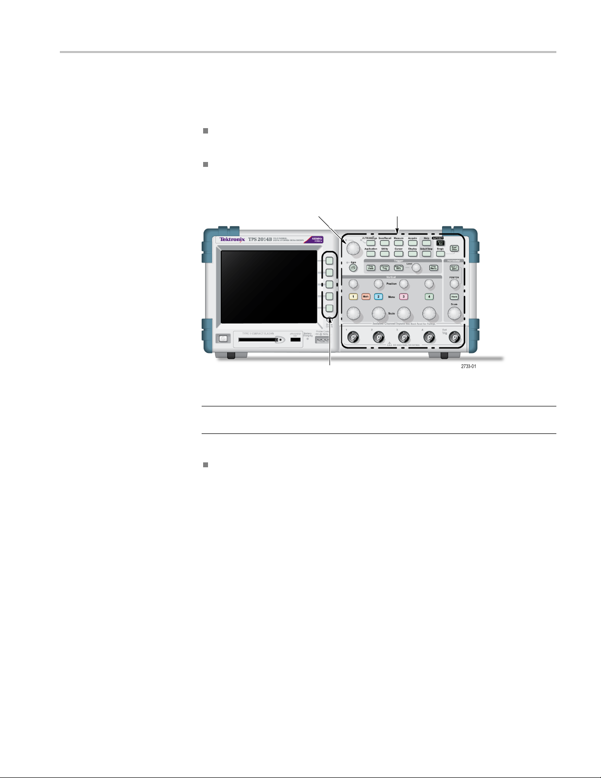
Operating Basics................................................................................................... 15
Display Area .................................................................................................. 16
Using the Menu System.................................. ................................ .................... 19
Vertical Controls ................................ ................................ .............................. 21
Horizontal Controls........................................................................................... 22
Trigger Controls............................................................................................... 23
Menu and Control Buttons................................................................................... 23
Input Connectors.............................................................................................. 25
Other Front-Panel Items...................................................................................... 26
Understanding Oscilloscope Functions .. . . . .... . ..... . ..... . ..... . ..... . ..... . ..... . ... . . ..... . ..... . ..... . .... 27
Setting Up the Oscilloscope . .... . ..... . ..... . ..... ..... . ..... . ..... . ..... . .... . . .... . ..... . ..... . ..... . .... . 27
Triggering................................ .................................. ................................ .... 28
Acquiring Signals. .................................. ................................ .......................... 30
Scaling and Positioning Waveforms . . ..... . ..... . .... . . .... . ..... . ..... . .... . ..... . ..... . .... . . .... . ..... . . 31
Taking Measurements ........................................................................................ 34
Application Examples........................................... ................................ .................. 37
Taking Simple Measurements ............................................................................... 38
Using Autorange to Examine a Series of Test Points............. ................................ ........ 43
Using an Isolated Channel to Analyze a Differential Communication Signal ................... ...... 44
TPS2000B Series Digital Oscilloscope User Manual i

Table of Contents
Viewing a Math I
nstantaneous Power Waveform . ................................ ........................ 45
Taking Cursor Measurements ..................... ................................ .......................... 46
Analyzing Signal Detail...................................................................................... 50
Capturing a Single-Shot Signal ............. ................................ ................................ 51
Measuring Propagation Delay ............................. ................................ .................. 53
Triggering on a Specific Pulse Width............................. ................................ .......... 54
Triggering on a Video Signal................ .................................. .............................. 55
Viewing Impedance Changes in a Network................................................................ 59
Math FFT............... .................................. ................................ .......................... 61
Setting Up the Time-Domain Waveform... . ..... . ..... . ... . . ..... . ..... . ..... . ..... . ..... . ... . . . .... . ..... 61
Displaying the FFT Spectrum ............................................................................... 64
Selecting an FFT Window ................................................................................... 65
Magnifying and Positioning an FFT Spectrum . . ..... . ... . . . .... . ..... . ..... . ..... . ..... . ..... . ... . . ..... . 68
Measuring an FFT Spectrum Using Cursors............................................................... 69
Communications (RS-232, Centronics, and RS-232/USB). ................................ .................. 71
Sending a Screen Image to an External Device ....................... ................................ .... 71
Setting Up and Testing the RS-232 Interface ..... . ..... . ..... . ..... . ..... . ..... . ..... . ..... . ..... . ..... . .. 73
Command Entry............................................................................................... 78
Setting Up and Using the RS-232/USB Cable.. . ... . . . .... . ..... . ..... . .... . ..... . ..... . .... . . .... . ..... . . 79
Removable Mass Storage ....................... ................................ ................................ .. 81
Installing and Removing a CompactFlash (CF) Card. . . ..... . ..... . ..... . ..... . .... . . .... . ..... . ..... . ... 81
File Management Conventions............................ ................................ .................. 82
Using the Save function of the Print Button ......................... ................................ ...... 83
Managing TPSBAT Battery Packs... . . ..... . .... . . ..... . .... . . ..... . .... . . ..... . .... . . ..... . .... . . ..... . .... . . .. 85
Maintaining Battery Packs..... .................................. ................................ ............ 86
General Charging Guidelines.......................................... ................................ ...... 86
Checking the Charge and Calibration Status... .................................. .......................... 87
Charging TPSBAT Battery Packs . . . ... . . . ... . . . ... . . . ... . . . ... . . . ... . . . ... . . . ... . . . ... . . . ..... . ..... . ..... . 88
Calibrating Battery Packs.................................................................................... 90
Handling Battery Packs ...................................................................................... 91
Storing and Transporting Battery Packs.................................................................... 91
Replacing Battery Packs ............. ................................ ................................ ........ 92
Reference......... ................................ ................................ ................................ .. 93
Acquire................................... ................................ ................................ ...... 93
Application .................................................................................................... 95
Autorange...................................................................................................... 95
Autoset................. ................................ .................................. ...................... 97
Cursor ........ ................................ ................................ ................................ 100
Default Setup .............................. ................................ ................................ .. 101
Display................. ................................ .................................. .................... 101
Help ...................... .................................. ................................ .................. 104
ii TPS2000B Series Digital Oscilloscope User Manual

Table of Contents
Horizontal.......... ................................ .................................. ........................ 104
Math ............................ ................................ .................................. ............ 105
Measure ...................................................................................................... 107
Print .......................................................................................................... 107
Probe Check................................................................................................. 108
Save/Recall .................................................................................................. 108
Trigger Con
trols..... ................................ ................................ ........................ 112
Utility . . ..... . ..... . ..... . ..... . ..... . ..... . ..... . ... . . . .... . . .... . ..... . ..... . ..... . ..... . ..... . ..... . ..... . . 118
Vertical Controls ................................ ................................ ............................ 120
Appendix A: TPS2000B Specifications....................................................................... 123
Oscilloscope Specifications................ ................................ ................................ 123
Appendix B: TPP0101 and TPP0201 Series 10X Passive Probes Information ......................... .. 131
Connect
ing the Probe to the Oscilloscope . ..... . .... . . . ..... . ..... . ..... . ..... . ..... . . ..... . ..... . ..... . 131
Compensating the Probe .................................................................................. 132
Connecting the Probe to the Circuit ...................................................................... 132
Standard Accessories....................................................................................... 133
Optional Accessories ....................................................................................... 134
Specifications.................................. .................................. ............................ 134
Perf
ormance Graphs ........................................................................................ 135
Safety Summary ............................................................................................ 136
Appendix C: Accessories ..... .................................. ................................ ................ 139
Appendix D: Cleaning .. .................................. ................................ ...................... 143
General Care ................................................................................................ 143
Cleaning ..................................................................................................... 143
Ap
pendix E: Default Setup..................................................................................... 145
Appendix F: Font Licenses ..................................................................................... 147
Appendix G: TPS2000B Compatible Probe Maximum Voltages .......................................... 149
Index
TPS2000B Series Digital Oscilloscope User Manual iii

General safety summary
General safet
ysummary
Review the fo
llowing safety precautions to avoid injury and prevent damage to
this product or any products connected to it.
To avoid pot
ential hazards, use this product only as specified.
Only qualified personnel should perform service procedures.
To avoid fir
e or personal
injury
Use proper
power c ord. Use only the power cord specified for this product and
certified for the country of use.
Connect a
nd disconnect properly. Do not connect or disconnect probes or test
leads while they are connected to a voltage source.
Connect a
nd disconnect properly. Connect the probe output to the measurement
instrument before connecting the probe to the circuit under test. Connect the
probe reference lead to the circuit under test before connecting the probe input.
Disconnect the probe input and the probe reference lead from the circuit under test
before disconnecting the probe from the measurement instrument.
Observe all terminal ratings. To avoid fire or shock hazard, observe all ratings
and markings on the product. Consult the product manual for further ratings
information before making connections to the product.
Do not apply a potential to a ny terminal, including the common terminal, that
exceeds the maximum rating o f that terminal.
Power disconnect. The power cord disconnects the product from the power source.
Donotblockthepowercord;itmustremain accessible to the user at all times.
Do not operate without covers. Do not operate this product with covers or panels
removed.
Do not operate with suspected failures. If you suspect that there is damage to this
product, have it inspected by qualified service personnel.
Avoid exposed circuitry. Do not touch exposed connections and components when
power is present.
Replace batteries properly. Replace batteries only with the specified type and
rating.
Recharge batteries properly. Recharge batteries for the recommended charge cycle
only.
Use proper AC adapter. Use only the AC adapter specified for this product.
iv TPS2000B Series Digital Oscilloscope User Manual

General safety summary
Do not operate i
n wet/damp conditions.
Do not operate in an explosive atmosphere.
Keep product surfaces clean and dry.
Provide prop
er ventilation. Refer to the manual's installation instructions for details
on installing the product so it has proper ventilation.
TPS2000B Series Digital Oscilloscope User Manual v
General safety summary
Termsinthismanual
These terms may
appear in this manual:
WARNING. Warning statements identify conditions or practices that could result
in injury or loss of life.
CAUTION. Caution statements identify conditions or practices that could result in
damage to this product or other property.
Symbols and terms on the
product
These terms may appear on the product:
DANGER in
dicates an injury hazard immediately accessible as you read
the marking.
WARNING
indicates an injury hazard not immediately accessible as you
read the marking.
CAUTIO
N indicates a hazard to property including the product.
The following symbol(s) may appear on the product:
vi TPS2000B Series Digital Oscilloscope User Manual

Compliance Information
This section lists the EMC (electromagnetic compliance), safety, and
environmental standards with which the instrument complies.
EMC Compliance
EC Declaration of
Conformity – EMC
Meets intent of Directive 2004/108/EC for Electromagnetic Compatibility.
Compliance was demonstrated to the following specifications as listed in the
Official Journal of the European Communities:
EN 61326-1:2006, EN 61326-2-1:2006. EMC requirements for electrical equipment
for measurement, control, and laboratory use.
123
CISPR 11:2003. Radiated and conducted emissions, Group 1, Class A
IEC 61000-4-2:2001. Electrostatic discharge immunity
IEC 61000-4-3:2002. RF electromagnetic field immunity
4
IEC 61000-4-4:2004. Electrical fast transient/burst immunity
IEC 61000-4-5:2001. Power line surge immunity
IEC 61000-4-6:2003. Conducted RF immunity
5
IEC 61000-4-11:2004. Voltage dips and interruptions immunity
6
EN 61000-3-2:2006. AC power line harmonic emissions
EN 61000-3-3:1995. Voltage changes, fluctuations, and fl icker
European Contact.
Tektronix UK, Ltd.
Western Peninsula
West ern Road
Bra
cknell, RG12 1RF
United Kingdom
1
This product is intended for use in nonresidential areas only. Use in residential areas may cause electromagnetic
interference.
2
Emissions which exceed the levels required by this standard may occur when this equipment is connected to a
test object.
3
To ensure compliance with the EMC standards listed here, high quality shielded interface cables should be used.
4
Theincreaseintracenoisewhilesubjectedtothetestfield (3 V/m over the frequency ranges of 80 MHz to 1 GHz
and 1.4 GHz to 2.0 GHz, with 80% amplitude modulation at 1 kHz) and (1 V/m over the frequency range of
2.0 GHz to 2.7 GHz, with 80% amplitude modulation at 1 kHz) is not to exceed two major divisions peak-to-peak.
Ambient conducted fields may induce triggering when the trigger threshold is offset less than one major division
from channel reference.
5
Theincreaseintracenoisewhilesubjectedtothetestfield (3 V rms over the frequency range of 150 kHz to
80 MHz, with 80% amplitude modulation at 1 kHz) is not to exceed one major division peak-to-peak. Ambient
TPS2000B Series Digital Oscilloscope User Manual vii

Compliance Information
conducted field
s may induce triggering when the trigger threshold is offset less than 0.5 major divisions from
channel reference.
6
Performance C
riterion C applied at the 70%/25 cycle Voltage-Dip and the 0%/250 cycle Voltage-Interruption test
levels (IEC 61000-4-11).
Australia / New Zealand
Declaration
of
Conformity – EMC
Complies with the EMC provision of the Radiocommunications Act per the
following st
andard, in accordance with ACMA:
CISPR 11:2003. Radiated and C onducted Emissions, Group 1, Class A, in
accordance
with EN 61326-1:2006 and EN 61326-2-1:2006.
viii TPS2000B Series Digital Oscilloscope User Manual

Compliance Information
Safety Compli
ance
EC Declaration of
Conformity – Low Voltage
Compliance was demonstrated to the following specification as listed in the
Official Journal of the European Communities:
Low Voltage Directive 2006/95/EC.
EN 61010-1: 2001. Safety requirements for electrical equipment for
measurement control and laboratory use.
U.S. Natio
nally Recognized
Testing Laboratory Listing
UL 61010-1:2004, 2nd Edition. Standard for electrical measuring and test
equipment.
Canadian Certification
CAN/CSA-C22.2 No. 61010-1:2004. Safety requirements for electrical
equipment for measurement, control, and laboratory use. Part 1
Additional Compliances
IEC 61010-1: 2001. Safety requirements for electrical equipment for
measurement, control, and laboratory use.
Equipment Type
Test a
nd measuring equipment.
Pollution Degree
Description
A measure of the contaminants that could occur in the environment around
and within a product. Typically the internal environment inside a product is
considered to be the same as the external. Products should be used only in the
environment for which they are rated.
Pollution D egree 1. No pollution or only dry, n onconductive pollution occurs.
Products in this category are generally encapsulated, hermetically sealed, or
located in clean rooms.
Pollution Degree 2. Normally only dry, nonconductive pollution occurs.
Occasionally a temporary conductivity that is caused by condensation must
b
e expected. This location is a typical office/home environment. Temporary
condensation occurs only when the product is out of service.
P
ollution Degree 3 . Conductive pollution, or dry, nonconductive pollution
that becomes conductive due to condensation. These are sheltered locations
where neither temperature nor humidity is controlled. The area is protected
from direct sunshine, rain, or direct wind.
Pollution Degree 4. Pollution that generates persistent conductivity through
conductive dust, rain, or snow. Typical outdoor locations.
Pollution Degree
Pollution Degree 2 (as defined in IEC 61010-1). Note: Rated for indoor use only.
TPS2000B Series Digital Oscilloscope User Manual ix

Compliance Information
Installation (Overvoltage)
Category Descriptions
Terminals on th
is product may have different installation (overvoltage) category
designations. The installation categories are:
Measurement C
ategory IV. For measurements performed at the source of
low-voltage installation.
Measuremen
t Category III. For measurements performed in the building
installation.
Measuremen
t Category II. For measurements performed on circuits directly
connected to the low-voltage installation.
Measureme
nt Category I. For measurements performed on circuits not
directly connected to MAINS.
Overvoltage Category
Overvoltage Category II (as defined in IEC 61010-1)
x TPS2000B Series Digital Oscilloscope User Manual

Compliance Information
Environmenta
l Considerations
This section provides information about the environmental impact of the product.
Product End-of-Life
Handling
Observe the following guidelines when recycling an instrument or component:
Equipment Recycling. Production of this equipment required the extraction and
use of natural resources. The equipment may contain substances that could be
harmful to
the environment or human health if improperly handled at the product’s
end of life. In order to avoid release of such substances into the environment and
to reduce the use of natural resources, we encourage you to recycle this product
in an appropriate system that will ensure that most of the materials are reused or
recycled appropriately.
This sym
bol indicates that this product complies with the applicable European
Union requirements according to Directives 2002/96/EC and 2006/66/EC
on waste electrical and electronic equipment (WEEE) and batteries. For
informa
tion about recycling options, check the Support/Service section of the
Tektronix Web site (www.tektronix.com).
Batter
y Recycling. This product contains a lithium ion (Li-ion) rechargeable
battery, which must be recycled or disposed of properly.
Lithi
um-Ion batteries are subject to disposal and recycling regulations that
vary by country and region. Always check and follow your applicable
regulations before disposing of any battery. Contact Rechargeable Battery
Recycling Corporation (www.rbrc.org) for U.S.A. and Canada, or your local
battery recycling organization.
Many countries prohibit the disposal of waste electronic equipment in
standard waste receptacles.
Place only discharged batteries in a battery collection container. Use electrical
tape or other approved covering over the battery connection points to prevent
short circuits.
T
ransporting Batteries
The capacity of the lithium ion rechargeable battery pack in this product is under
100 Wh. The lithium-equivalent content, as defined by the UN Manual of Tests
andCriteriaPartIIISection38.3,isunder8gperpackand1.5gperindividual
cell.
Always check all applicable local, national, and international regulations
before transporting a Lithium-Ion battery.
Transporting an end-of-life, damaged, or recalled battery may, in certain
cases, be specifically limited or prohibited.
TPS2000B Series Digital Oscilloscope User Manual xi

Compliance Information
Restriction of Hazardous
Substances
This product ha
s been classified as Monitoring and Control equipment, and is
outside the scope of the 2002/95/EC RoHS Directive.
xii TPS2000B Series Digital Oscilloscope User Manual

Preface
Preface
This manual c
ontains operating information for the TPS2000B Series Digital
Storage Oscilloscopes. The manual consists of the following chapters:
The Getting
Started chapter briefly describes features of the oscilloscope
and provides installation instructions.
The Operat
ing Basics chapter covers operating principles of the oscilloscopes.
The Understanding Oscilloscope Functions chapter describes basic operations
and functi
ons of an oscilloscope: setting up the oscilloscope, triggering,
acquiring data, scaling and positioning waveforms, and taking measurements.
The Appl
ication Examples chapter provides examples on how to solve a
variety of measurement problems.
The Math
FFT chapter describes how t o use the Math Fast Fourier Transform
function to convert a time-domain signal into its frequency components
(spectrum).
The Communications chapter d escribes how to set up the RS-232 a nd
Centronics ports to use the oscilloscope with external devices, such as printers
and computers.
The Removable Mass S torage chapter describes how to use a CompactFlash
card and oscilloscope functions available when a card is in use.
The Managing TPSBAT Battery Packs chapter describes how to use, charge,
calibrate, and replace battery packs.
The Reference chapter describes the selections or available range of values
for each option.
The Appendix A: TPS2000B Specifications chapter includes electrical,
environmental, and physical specifications for the oscilloscope.
The Appendix B: TPP0101 and TPP0201 Series Probes Information chapter
includes information on and specifications for the TPP0101 and TPP0201
probes.
The Appendix C: Ac cessories chapter briefly describes standard and optional
accessories.
The Appendix D: Cleaning chapter describes how to take care of the
oscilloscope.
The Appendix E: Default Setup chapter contains a list of the menus and
controls with the default (factory) settings that are recalled when you push
the Default Setup front-panel button.
TPS2000B Series Digital Oscilloscope User Manual xiii

Preface
The Appendix F:
Font Licenses chapter provides the licenses to use specific
Asian fonts.
The Appendix G
: TPS2000B Compatible Probe Maximum Voltages chapter
lists the maximum voltages of compatible probes.
Help System
The oscilloscope has a Help system with topics that cover all the features of the
oscilloscope. You can use the Help system to display several kinds of information:
General information about understanding and using the oscilloscope, such
as Using the Menu System.
Information about specific menus and controls, such as the Vertical Position
Control.
Advice about problems you may face while using an oscilloscope, such as
Reducing Noise.
The Help system provides several ways to find the information you need:
context-sensitive help, hyperlinks, and an index.
Context-Sensitive Help
The os
cilloscope displays information about the last menu displayed on the
screen when you push the Help front-panel button. When viewing help topics,
an LED lights next to the multipurpose knob to indicate that the knob is active.
If the topic uses more than one page, turn the multipurpose knob to move from
page to page within the topic.
Hyperlinks
Most of the help topics contain phrases marked with angle bracket s, such as
<Autoset>. These are links to other topics. Turn the multipurpose knob to move
the highlight from one link to another. Push the Show Topic option button to
display the topic corresponding to the highlighted link. Push the Back option
b
utton to return to the previous topic.
Index
Push the front-panel Help button, then push the Index option button. Push the
Page Up or Page Down option buttons until you find the index page that contains
the topic you want to view. Turn the multipurpose knob to highlight a help topic.
Push the Show Topic option button to display the topic.
NOTE. Push the Exit option button or any menu button to remove the Help text
from the screen and return to displaying waveforms.
xiv TPS2000B Series Digital Oscilloscope User Manual
Preface
Conventions
This manual uses the following conventions:
Front-panel buttons, knobs and connectors appear as displayed. For example:
Help.
Menu options appear with the first letter of each word in upper case. For
example: Peak Detect, Window Zone.
Multipurp
ose knob
Front-pan
el buttons and knob labels - As displayed
Option buttons - First letter of each word on screen is upper ca se
NOTE. Option buttons may also be called screen buttons, side-menu buttons,
bezel buttons, or soft keys.
The ► delimiter separates a series o f button pushes. For example, Utility
► Options ► RS232 Setup means that you push the Utility front-panel
but
ton, then push the Options option button, and then push the RS232 Setup
option button. Multiple pushes of an option button may be required to select
the desired option.
TPS2000B Series Digital Oscilloscope User Manual xv

Preface
xvi TPS2000B Series Digital Oscilloscope User Manual

Getting Started
TPS2000B Series Digital Storage Oscilloscopes are small, lightweight, benchtop
instruments, which you can use to take ground-referenced measurements.
This chapter describes how to do the following tasks:
Take floating measurements
Install your product
Charge battery pack
s
Perform a brief functional check
Perform a probe check and compensate probes
Match your probe attenuation factor
Use the self calibration routine
NOTE. You can select a language to display on the screen when you power on the
oscilloscope. At any time, you can also access the Utility ► Language option to
select a language.
General Features
The next table and list d
escribe the general features.
Model Channels Bandwidth Sample rate
TPS2012B
2 100 MHz
1.0 GS /s
TPS2014B
4 100 MHz
1.0 GS /s
TPS2024B
4 200 MHz
2.0 GS /s
Battery powered or line powered
Two rechargeable battery packs (second battery pack optional)
Independently isolated channels with no shared common ground
TPS2PWR1 Power Analysis application (optional)
Support for compatible voltage probes and current probes
Context-sensitive help system
Color LCD display
Selectable 20 MHz bandwidth limit
2500 point record length for each channel
Autoset
TPS2000B Series Digital Oscilloscope User Manual 1

Getting Started
Autoranging fo
r quick set up and hands-free operation
Probe Check Wizard
Cursors with readouts
Trigger frequency readout
Eleven automatic measurements
Waveform averaging and peak detection
Dual time b
ase
Math functions: +, -, and × operations
Math Fast Fourier Transform (FFT)
Pulse Width trigger capability
Video trigger capability with line-selectable triggering
External trigger
Setup a
nd waveform storage
Removablemassstorage
Variable persistence display
RS-232 and Centronics ports
OpenChoice PC Communications software
User interface and help topics in ten languages
2 TPS2000B Series Digital Oscilloscope User Manual

Getting Started
Taking Floating Measurements
For taking floating measurements, the oscilloscope channel and Ext Trig inputs (3
MΩ ) are isolated from the oscilloscope chassis and from each other. This allows
independent floating measurements with channel 1, channel 2, and Ext Trig (and
with channel 3 and channel 4 on four channel models).
The osc
illoscope inputs float even when the oscilloscope is connected to a
grounded power supply, a grounded printer, or a grounded computer.
Most o
ther oscilloscopes share a common re ference for the oscilloscope channel
and Ext Trig inputs. This reference is typically connected to earth ground through
the power cord. With common-referenced oscilloscopes, all input signals must
have the same common reference when you take any multi-channel measurements.
Without differential preamplifiers or external signal isolators, common-referenced
oscilloscopes are not suitable for taking floating measurements.
Probe Connection
WAR NI NG . To prevent electrical shock, do not exceed the measurement or floating
vo
ltage ratings for the oscilloscope input BNC connector, probe tip, or probe
reference lead.
TPS2000B Series Digital Oscilloscope User Manual 3

Getting Started
Understand the
voltage ratings for the probes you are using and do not exceed
those ratings. The following voltage ratings are important to know and understand:
The maximum me
asurement voltage from the probe tip and BNC signal to the
probe reference lead
The maximum
measurement voltage from the probe tip and BNC shell to
earth ground
The maximum
floating voltage from the probe reference lead to earth ground
WARNING. To avoid an electric shock, do not use probes that require a ground
connection, such as the Tektronix P5200 High Voltage Differential Probe,
with the TPS2000B series oscilloscopes. The P5200 High Voltage Differential
Probe requires an oscilloscope with grounded inputs and the TPS2000B series
oscilloscopes have floating inputs (isolated inputs).
WARNING. Do not float the TPP0101 or TPP0201 probe reference lead to >
30 V
RMS
. Use the P5120 probe (floatable to 600 V
RMS
CAT II or 300 V
RMS
CAT III)
or simi
larly rated, passive, high voltage probe (not the ground referenced P5100
probe), or an appropriately rated, high voltage, differential probe when floating
the reference lead above 30 V
RMS
, subject to the ratings of such high voltage probe.
To avoid electric shock when using probes with exposed metal parts, do not
connect the reference lead to voltages above 30 V
RMS
.
These voltage ratings depend on the probe and your application. (See page 123,
TPS2000B Specifications.)
This manual contains more information on probe safety. (See page 10, Probe
Safety.)
Attach the Reference
Leads Correctly
Y
ou must attach the probe re ference lead for each channel directly to your circuit.
These attachments are required because the oscilloscope channels are electrically
isolated; they do not share a common connection. Use the shortest possible
reference lead with each probe to maintain good signal fidelity.
The probe reference lead presents a higher capacitive load to the circuit under test
than the probe tip. When taking a floating measurement between two nodes of a
circuit, attach the probe reference lead to the lowest impedance or least dynamic
of the two nodes.
4 TPS2000B Series Digital Oscilloscope User Manual
Getting Started
BNC Connectors
The oscillosco
pe BNC reference connection is made on the inside of the BNC
connector. The black bayonet on the outside of the BNC connectors does not
provide electrical contact. For a good connection, make sure your probe or cable
connector is pushed on and twist locked. Replace cables or probes that have
worn connectors.
Unterminated BNC Inputs
The black bayonet on the outside of the BNC input connectors does not shield
the connector input from unwanted electrical noise from nearby circuits. Connect
a50Ω terminator or a BNC shorting plug to the input BNC connector when
establishing a "No Signal" baseline condition.
Installation
You can use the oscilloscope AC adapter to power the oscilloscope or to charge
battery
packs when installed. To use the oscilloscope AC adapter as the power
source, follow these ste ps:
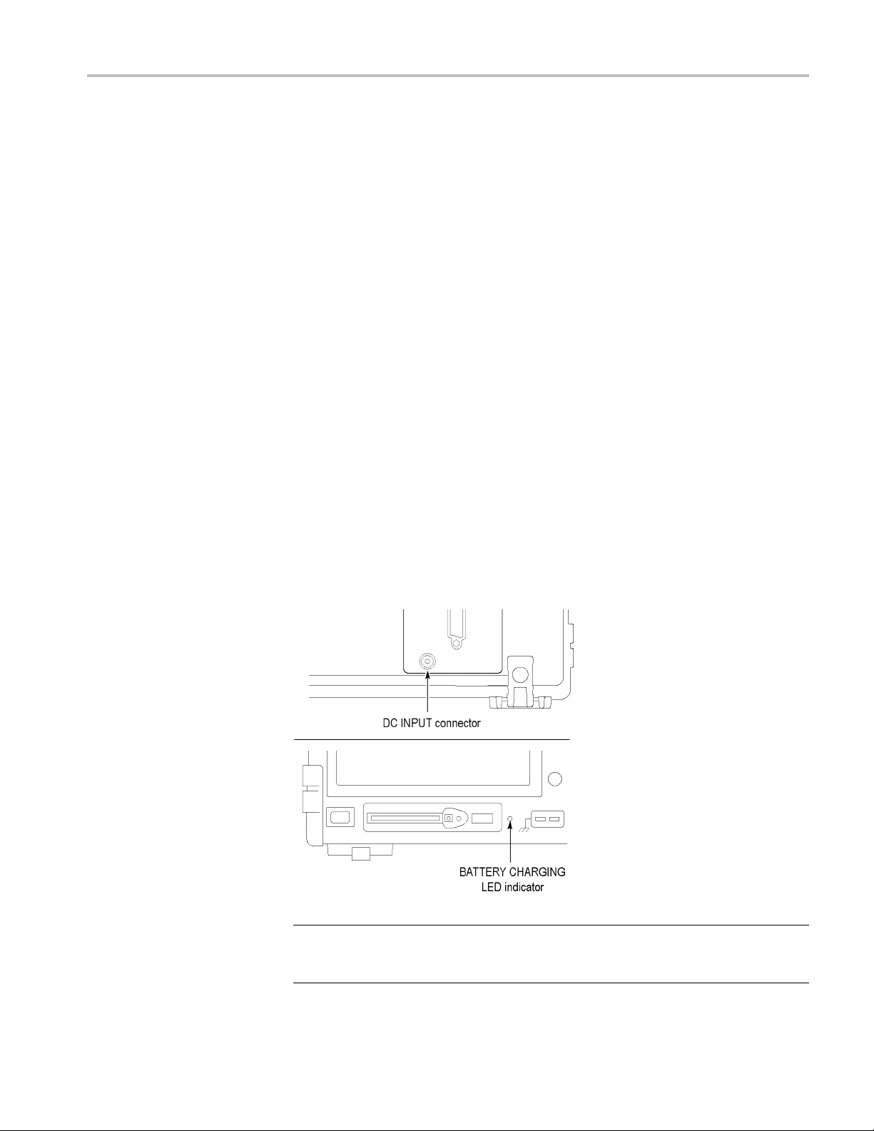
1. Insert
the DC connector end of the adapter into the DC INPUT connector on
the back of the oscilloscope.
2. Conne
ct the appropriate power cord between the oscilloscope AC adapter
and an electrical outlet.
If ba
ttery packs are installed, an LED lights on the front of the oscilloscope to
indicate when the battery packs are charging.
NOTE. The oscilloscope contains a temperature-sensing fan for cooling that
forces air through vents on the bottom and on the side of the oscilloscope. To
allow air to flow freely through the oscilloscope, do not block these vents.
TPS2000B Series Digital Oscilloscope User Manual 5
Getting Started
Battery Packs
The oscillosco
pe can accommodate two TPSBAT battery packs. The product
includes one battery pack that is not installed when shipped. The amount of time
you can operate the oscilloscope with battery packs depends on the oscilloscope
model.
Oscilloscope Amount of time to operate
2 channel 5.5 hours on one battery pack, 11 hours on two
4 channel 4.5 hours on one battery pack, 9 hours on two
NOTE. The o
scilloscope displays a message when approximately 10 minutes of
operating time remain on the battery packs.
This manu
al contains details on how to use, charge, calibrate, and replace battery
packs. For example, battery packs need to be calibrated to accurately report
available operating time. (See page 85, Managing TPSBAT Battery Packs.)
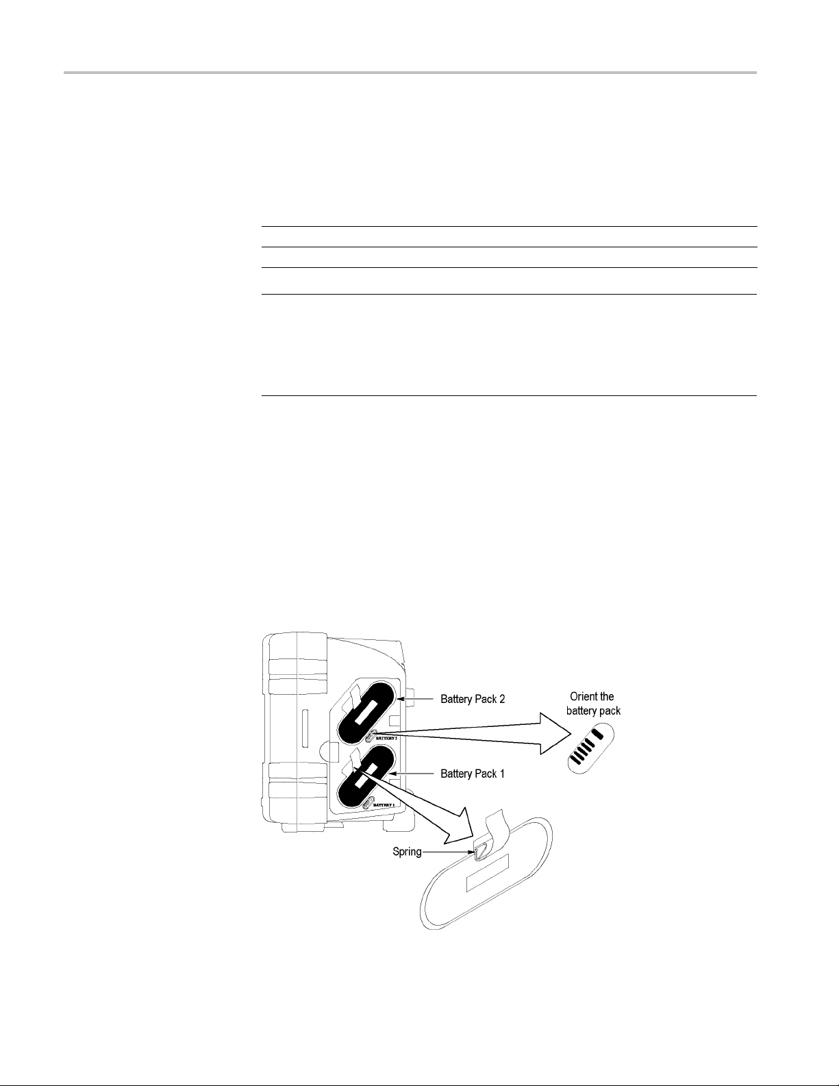
To install battery packs, follow these steps:
1. Press t
he battery compartment door latch on the right side panel and open the
battery compartment.
2. Orien
t the battery pack as shown on the oscilloscope, and install the pack.
Battery packs are keyed, so you can insert them only one way.
For s
ingle battery pack use, install a pack in the lower receptacle. This lowers
the center of gravity.
3. Clo
se the battery compartment door.
6 TPS2000B Series Digital Oscilloscope User Manual
 Loading...