


DPO4000 Series
Digital Phosphor Oscilloscopes
User Manual
www.tektronix.com
071-1785-00

Copyright © Tektronix. All rights reserved. Licensed software products are owned by Tektronix or its subsidiaries or suppliers, and are protected by national copyright laws and international treaty provisions.
Tektronix products are covered by U.S. and foreign patents, issued and pending. Information in this publication supersedes that in all previously published material. Specifications and price change privileges reserved.
TEKTRONIX and TEK are registered trademarks of Tektronix, Inc.
e*Scope, iView, OpenChoice, TekSecure, and TekVPI are registered trademarks of Tektronix, Inc.
Wave Inspector is a trademark of Tektronix, Inc.
Contacting Tektronix
Tektronix, Inc.
14200 SW Karl Braun Drive
P.O. Box 500
Beaverton, OR 97077
USA
For product information, sales, service, and technical support:
In North America, call 1-800-833-9200.
Worldwide, visit www.tektronix.com to find contacts in your area.
Warranty 4
Tektronix warrants that this product will be free from defects in materials and workmanship for a period of three (3) years from the date of shipment. If any such product proves defective during this warranty period, Tektronix, at its option, either will repair the defective product without charge for parts and labor, or will provide a replacement in exchange for the defective product. Parts, modules and replacement products used by Tektronix for warranty work may be new or reconditioned to like new performance. All replaced parts, modules and products become the property of Tektronix.
In order to obtain service under this warranty, Customer must notify Tektronix of the defect before the expiration of the warranty period and make suitable arrangements for the performance of service. Customer shall be responsible for packaging and shipping the defective product to the service center designated by Tektronix, with shipping charges prepaid. Tektronix shall pay for the return of the product to Customer if the shipment is to a location within the country in which the Tektronix service center is located. Customer shall be responsible for paying all shipping charges, duties, taxes, and any other charges for products returned to any other locations.
This warranty shall not apply to any defect, failure or damage caused by improper use or improper or inadequate maintenance and care. Tektronix shall not be obligated to furnish service under this warranty a) to repair damage resulting from attempts by personnel other than Tektronix representatives to install, repair or service the product; b) to repair damage resulting from improper use or connection to incompatible equipment; c) to repair any damage or malfunction caused by the use of non-Tektronix supplies; or d) to service a product that has been modified or integrated with other products when the effect of such modification or integration increases the time or difficulty of servicing the product.
THIS WARRANTY IS GIVEN BY TEKTRONIX WITH RESPECT TO THE PRODUCT IN LIEU OF ANY OTHER WARRANTIES, EXPRESS OR IMPLIED. TEKTRONIX AND ITS VENDORS DISCLAIM ANY IMPLIED WARRANTIES OF MERCHANTABILITY OR FITNESS FOR A PARTICULAR PURPOSE. TEKTRONIX’ RESPONSIBILITY TO REPAIR OR REPLACE DEFECTIVE PRODUCTS IS THE SOLE AND EXCLUSIVE REMEDY PROVIDED TO THE CUSTOMER FOR BREACH OF THIS WARRANTY. TEKTRONIX AND ITS VENDORS WILL NOT BE LIABLE FOR ANY INDIRECT, SPECIAL, INCIDENTAL, OR CONSEQUENTIAL DAMAGES IRRESPECTIVE OF WHETHER TEKTRONIX OR THE VENDOR HAS ADVANCE NOTICE OF THE POSSIBILITY OF SUCH DAMAGES.

|
Table of Contents |
Table of Contents |
|
General Safety Summary . . .. . . . . . . . . . . . . . . . . . . . . . . . . . . . . . . . . . . . . . . . . . . . . . . . . . . . . . . . . . . . . . . . . . . . . . . . . . . . . . . . . . . . . . . . . . . . . . . . . |
. . . . . . . . . . . . . . . v |
Environmental Considerations . . . . . . . . . . . . . . . . . . . . . . . . . . . . . . . . . . . . . . . . . . . . . . . . . . . . . . . . . . . . . . . . . . . . . . . . . . . . . . . . . . . . . . . . . . . . . . . . |
. . . .. . . . . . . . viii |
Preface. . . . . . . . . . . . . . . . . . . . . . . . . . . . . . . . . . . . . . . . . . . . . . . . . . . . . . . . . . . . . . . . . . . . . . . . . . . . . . . . . . . . . . . . . . . . . . . . . . . . . . . . . . . . . . . . . . . . . . . .. |
. . . . . . . . . . . . . . x |
Key Features. . . . . . . . . . . . . . . . . . . . . . . . . . . . . . . . . . . . . . . . . . . . . . . . . . . . . . . . . . . . . . . . . . . . . . . . . . . . . . . . . . . . . . . . . . . . . . . . . . . . . . . . . . . . . |
. . . . . . .. . . . . . . x |
Where to Find More Information. . . . . . . . . . . . . . . . . . . . . . . . . . . . . . . . . . . . . . . . . . . . . . . . . . . . . . . . . . . . . . . . . . . . . . . . . . . . . . . . . . . . . . . . . |
. . . . . . . . . . . . xii |
Conventions Used in This Manual. . . . . . . . . . . . . . . . . . . . . . . . . . . . . . . . . . . . . . . . . . . . . . . . . . . . . . . . . . . . . . . . . . . . . . . . . . . . . . . . . . . . . . . |
. . . . . . . . . . . . xiii |
Installation . . . . . . . . . . . . . . . . . . . . . . . . . . . . . . . . . . . . . . . . . . . . . . . . . . . . . . . . . . . . . . . . . . . . . . . . . . . . . . . . . . . . . . . . . . . . . . . . . . . . . . . . . . . . . . . . . . .. . |
. . . . . . . . . . . . . 1 |
Before Installation. . . . . . . . . . . . . . . . . . . . . . . . . . . . . . . . . . . . . . . . . . . . . . . . . . . . . . . . . . . . . . . . . . . . . . . . . . . . . . . . . . . . . . . . . . . . . . . . . . . . . . . . |
. . . . .. . . . . . . . 1 |
Operating Considerations . . . . . . . . . . . . . . . . . . . . . . . . . . . . . . . . . . . . . . . . . . . . . . . . . . . . . . . . . . . . . . . . . . . . . . . . . . . . . . . . . . . . . . . . . . . . . . . |
. . . . . . . . .. . . . 6 |
Connecting Probes . . . . . . . . . . . . . . . . . . . . . . . . . . . . . . . . . . . . . . . . . . . . . . . . . . . . . . . . . . . . . . . . . . . . . . . . . . . . . . . . . . . . . . . . . . . . . . . . . . . . . . |
. . . . . . . . . . . . 10 |
Powering On the Oscilloscope . . . . . . . . . . . . . . . . . . . . . . . . . . . . . . . . . . . . . . . . . . . . . . . . . . . . . . . . . . . . . . . . . . . . . . . . . . . . . . . . . . . . . . . . . . |
. . . . . . . . . . . . 11 |
Powering Off the Oscilloscope . . . . . . . . . . . . . . . . . . . . . . . . . . . . . . . . . . . . . . . . . . . . . . . . . . . . . . . . . . . . . . . . . . . . . . . . . . . . . . . . . . . . . . . . . . |
. . . . . . . . . . .. 14 |
Functional Check . . . . . . . . . . . . . . . . . . . . . . . . . . . . . . . . . . . . . . . . . . . . . . . . . . . . . . . . . . . . . . . . . . . . . . . . . . . . . . . . . . . . . . . . . . . . . . . . . . . . . . . . |
. . . . . . . .. . . . 15 |
Compensating the Probe . .. . . . . . . . . . . . . . . . . . . . . . . . . . . . . . . . . . . . . . . . . . . . . . . . . . . . . . . . . . . . . . . . . . . . . . . . . . . . . . . . . . . . . . . . . . . . . . |
. . . . . . . . . . . . 17 |
Installing an Application Module. . .. . . . . . . . . . . . . . . . . . . . . . . . . . . . . . . . . . . . . . . . . . . . . . . . . . . . . . . . . . . . . . . . . . . . . . . . . . . . . . . . . . . . . . |
. . . . . . . . . . . . 19 |
Changing the User Interface Language . . . . . . . . . . . . . . . . . . . . . . . . . . . . . . . . . . . . . . . . . . . . . . . . . . . . . . . . . . . . . . . . . . . . . . . . . . . . . . . . . |
. . . . . . . . . . . . 20 |
Changing the Date and Time . .. . . . . . . . . . . . . . . . . . . . . . . . . . . . . . . . . . . . . . . . . . . . . . . . . . . . . . . . . . . . . . . . . . . . . . . . . . . . . . . . . . . . . . . . . . |
. . . . . . . . . . . . 23 |
Signal Path Compensation . . . . . . . . . . . . . . . . . . . . . . . . . . . . . . . . . . . . . . . . . . . . . . . . . . . . . . . . . . . . . . . . . . . . . . . . . . . . . . . . . . . . . . . . . . . . . . |
. . . . . . . . . . . . 25 |
Upgrading Firmware . . . . . . . . . . . . . . . . . . . . . . . . . . . . . . . . . . . . . . . . . . . . . . . . . . . . . . . . . . . . . . . . . . . . . . . . . . . . . . . . . . . . . . . . . . . . . . . . . . . . . |
. . . . . . . . .. . . 28 |
Connecting Your Oscilloscope to a Computer . . . . . . . . . . . . . . . . . . . . . . . . . . . . . . . . . . . . . . . . . . . . . . . . . . . . . . . . . . . . . . . . . . . . . . . . . . |
. . . . . . . . . . . . 34 |
DPO4000 Series User Manual |
i |

Table of Contents |
|
|
Get Acquainted with the Instrument. .. . . . . . . . . . . . . . . . . . . . . . . . . . . . . . . . . . . . . . . . . . . . . . . . . . . . . . . . . . . . . . . . . . . . . . . . . . . |
. . . . . . . . . . . . . . . . . . . . . . . . . . |
45 |
Front-Panel Menus and Controls . . .. . . . . . . . . . . . . . . . . . . . . . . . . . . . . . . . . . . . . . . . . . . . . . . . . . . . . . . . . . . . . . . . . . . . . . . |
. . . . . . . . . . . . . . . . . . . . . . . . . . |
45 |
Front-Panel Connectors . . .. . . . . . . . . . . . . . . . . . . . . . . . . . . . . . . . . . . . . . . . . . . . . . . . . . . . . . . . . . . . . . . . . . . . . . . . . . . . . . . . |
. . . . . . . . . . . . . . . . . . . . . . . . . . |
66 |
Side-Panel Connector .. . . . . . . . . . . . . . . . . . . . . . . . . . . . . . . . . . . . . . . . . . . . . . . . . . . . . . . . . . . . . . . . . . . . . . . . . . . . . . . . . . . . |
. . . . . . . . . . . . . . . . . . . . . . . . . . |
67 |
Rear-Panel Connectors. . . . . . . . . . . . . . . . . . . . . . . . . . . . . . . . . . . . . . . . . . . . . . . . . . . . . . . . . . . . . . . . . . . . . . . . . . . . . . . . . . . . |
. . . . . . . . . . . . . . . . . . . . . . .. . . |
68 |
Acquire the Signal . . . . . . . . . . . . . . . . . . . . . . . . . . . . . . . . . . . . . . . . . . . . . . . . . . . . . . . . . . . . . . . . . . . . . . . . . . . . . . . . . . . . . . . . . . . . . . . |
. . . . . . . . . . . . . . . .. . . . . . . . . . |
70 |
Setting Up Signal Input . . . . . . . . . . . . . . . . . . . . . . . . . . . . . . . . . . . . . . . . . . . . . . . . . . . . . . . . . . . . . . . . . . . . . . . . . . . . . . . . . . . . |
. . . . . . . . . . . . . . . . . . . . . . . . . . |
70 |
Using the Default Setup . . . . . . . . . . . . . . . . . . . . . . . . . . . . . . . . . . . . . . . . . . . . . . . . . . . . . . . . . . . . . . . . . . . . . . . . . . . . . . . . . . . |
. . . . . . . . . . . . . . . . . . . . . . . .. . |
73 |
Using Autoset . . . . . . . . . . . . . . . . . . . . . . . . . . . . . . . . . . . . . . . . . . . . . . . . . . . . . . . . . . . . . . . . . . . . . . . . . . . . . . . . . . . . . . . . . . . . . . |
. . . . . . . . . . . . . . . . . . . . .. . . . . |
74 |
Acquisition Concepts . . . . . . . . . . . . . . . . . . . . . . . . . . . . . . . . . . . . . . . . . . . . . . . . . . . . . . . . . . . . . . . . . . . . . . . . . . . . . . . . . . . . . . |
. . . . . . . . . . . . . . . . . . . . . .. . . . |
75 |
How the Acquisition Modes Work . . . . . . . . . . . . . . . . . . . . . . . . . . . . . . . . . . . . . . . . . . . . . . . . . . . . . . . . . . . . . . . . . . . . . . . . . |
. . . . . . . . . . . . . . . . . . . . . . . . . . |
78 |
Changing the Acquisition Mode and Record Length. . . . . . . . . . . . . . . . . . . . . . . . . . . . . . . . . . . . . . . . . . . . . . . . . . . . . . |
. . . . . . . . . . . . . . . . . . . . . . . . . . |
80 |
Using Roll Mode . . . . . . . . . . . . . . . . . . . . . . . . . . . . . . . . . . . . . . . . . . . . . . . . . . . . . . . . . . . . . . . . . . . . . . . . . . . . . . . . . . . . . . . . . . . |
. . . . . . . . . . . . . . . . . . . . . . .. . . |
83 |
Defining a Serial Bus . . . . . . . . . . . . . . . . . . . . . . . . . . . . . . . . . . . . . . . . . . . . . . . . . . . . . . . . . . . . . . . . . . . . . . . . . . . . . . . . . . . . . . |
. . . . . . . . . . . . . . . . . . . . . . . . . . |
84 |
Trigger Setup and Run . . . . . . . . . . . . . . . . . . . . . . . . . . . . . . . . . . . . . . . . . . . . . . . . . . . . . . . . . . . . . . . . . . . . . . . . . . . . . . . . . . . . . . . . . . |
. . . . . . . . . . . . . . . . . . .. . . . . . . |
91 |
Triggering Concepts . . .. . . . . . . . . . . . . . . . . . . . . . . . . . . . . . . . . . . . . . . . . . . . . . . . . . . . . . . . . . . . . . . . . . . . . . . . . . . . . . . . . . . . |
. . . . . . . . . . . . . . . . . . . . . . . . . . |
91 |
Choosing a Trigger.. . . . . . . . . . . . . . . . . . . . . . . . . . . . . . . . . . . . . . . . . . . . . . . . . . . . . . . . . . . . . . . . . . . . . . . . . . . . . . . . . . . . . . . . . . . . . . . . . . . . . . . . . . . . . . . . . . |
98 |
|
Selecting Triggers. .. . . . . . . . . . . . . . . . . . . . . . . . . . . . . . . . . . . . . . . . . . . . . . . . . . . . . . . . . . . . . . . . . . . . . . . . . . . . . . . . . . . . . . . . |
. . . . . . . . . . . . . . . . . . . . . . . . . . |
99 |
Triggering on Buses . . .. . . . . . . . . . . . . . . . . . . . . . . . . . . . . . . . . . . . . . . . . . . . . . . . . . . . . . . . . . . . . . . . . . . . . . . . . . . . . . . . . . . . |
. . . . . . . . . . . . . . . . . . . . . . . . . |
102 |
Checking Trigger Status . . .. . . . . . . . . . . . . . . . . . . . . . . . . . . . . . . . . . . . . . . . . . . . . . . . . . . . . . . . . . . . . . . . . . . . . . . . . . . . . . . . |
. . . . . . . . . . . . . . . . . . . . . . . . . |
107 |
Using A (Main) and B (Delayed) Triggers . . . . . . . . . . . . . . . . . . . . . . . . . . . . . . . . . . . . . . . . . . . . . . . . . . . . . . . . . . . . . . . . . |
. . . . . . . . . . . . . . . . . . . . . . . . . |
107 |
Starting and Stopping an Acquisition. . .. . . . . . . . . . . . . . . . . . . . . . . . . . . . . . . . . . . . . . . . . . . . . . . . . . . . . . . . . . . . . . . . . . . |
. . . . . . . . . . . . . . . . . . . . . . . . . |
111 |
ii |
DPO4000 Series User Manual |
|

|
Table of Contents |
Display Waveform Data . . . . . . . . . . . . . . . . . . . . . . . . . . . . . . . . . . . . . . . . . . . . . . . . . . . . . . . . . . . . . . . . . . . . . . . . . . . . . . . . . . . . . . . . . . . . . . . . . . . . . . |
. . . . . .. . . . . . 112 |
Adding and Removing a Waveform . . . . . . . . . . . . . . . . . . . . . . . . . . . . . . . . . . . . . . . . . . . . . . . . . . . . . . . . . . . . . . . . . . . . . . . . . . . . . . . . . . . . . |
. . . . . . . . . . . 112 |
Setting the Display Style and Persistence . . . . . . . . . . . . . . . . . . . . . . . . . . . . . . . . . . . . . . . . . . . . . . . . . . . . . . . . . . . . . . . . . . . . . . . . . . . . . . |
. . . . . . . . . . . 112 |
Setting Waveform and Graticule Intensity. . . . . . . . . . . . . . . . . . . . . . . . . . . . . . . . . . . . . . . . . . . . . . . . . . . . . . . . . . . . . . . . . . . . . . . . . . . . . . . |
. . . . . . . . . . . 115 |
Setting the Graticule Style . . . . . . . . . . . . . . . . . . . . . . . . . . . . . . . . . . . . . . . . . . . . . . . . . . . . . . . . . . . . . . . . . . . . . . . . . . . . . . . . . . . . . . . . . . . . . . . |
. . . . . . . .. . . 117 |
Setting the LCD Backlight . . . . . . . . . . . . . . . . . . . . . . . . . . . . . . . . . . . . . . . . . . . . . . . . . . . . . . . . . . . . . . . . . . . . . . . . . . . . . . . . . . . . . . . . . . . . . . . |
. . . . . . . . . .. 118 |
Scaling and Positioning a Waveform . . . . . . . . . . . . . . . . . . . . . . . . . . . . . . . . . . . . . . . . . . . . . . . . . . . . . . . . . . . . . . . . . . . . . . . . . . . . . . . . . . . . |
. . . . . . . . . . . 120 |
Setting Input Parameters . . . . . . . . . . . . . . . . . . . . . . . . . . . . . . . . . . . . . . . . . . . . . . . . . . . . . . . . . . . . . . . . . . . . . . . . . . . . . . . . . . . . . . . . . . . . . . . . |
. . . . . . . . .. . 122 |
Analyze Waveform Data. . . . . . . . . . . . . . . . . . . . . . . . . . . . . . . . . . . . . . . . . . . . . . . . . . . . . . . . . . . . . . . . . . . . . . . . . . . . . . . . . . . . . . . . . . . . . . . . . . . . . . . |
. . . . .. . . . . . 129 |
Taking Automatic Measurements. . . . . . . . . . . . . . . . . . . . . . . . . . . . . . . . . . . . . . . . . . . . . . . . . . . . . . . . . . . . . . . . . . . . . . . . . . . . . . . . . . . . . . . . |
. . . . . . . . . . . 129 |
Selecting Automatic Measurements. . . . . . . . . . . . . . . . . . . . . . . . . . . . . . . . . . . . . . . . . . . . . . . . . . . . . . . . . . . . . . . . . . . . . . . . . . . . . . . . . . . . . |
. . . . . . . . . . . 131 |
Customizing an Automatic Measurement . . . . . . . . . . . . . . . . . . . . . . . . . . . . . . . . . . . . . . . . . . . . . . . . . . . . . . . . . . . . . . . . . . . . . . . . . . . . . . . |
. . . . . . . . . . . 137 |
Taking Manual Measurements with Cursors . . .. . . . . . . . . . . . . . . . . . . . . . . . . . . . . . . . . . . . . . . . . . . . . . . . . . . . . . . . . . . . . . . . . . . . . . . . . |
. . . . . . . . . . . 144 |
Using Math Waveforms . . . . . . . . . . . . . . . . . . . . . . . . . . . . . . . . . . . . . . . . . . . . . . . . . . . . . . . . . . . . . . . . . . . . . . . . . . . . . . . . . . . . . . . . . . . . . . . . . . |
. . . . . . . . . . . 150 |
Using FFT . . . . . . . . . . . . . . . . . . . . . . . . . . . . . . . . . . . . . . . . . . . . . . . . . . . . . . . . . . . . . . . . . . . . . . . . . . . . . . . . . . . . . . . . . . . . . . . . . . . . . . . . . . . . . . . . |
. . . . . . .. . . . 153 |
Using Advanced Math . . . . . . . . . . . . . . . . . . . . . . . . . . . . . . . . . . . . . . . . . . . . . . . . . . . . . . . . . . . . . . . . . . . . . . . . . . . . . . . . . . . . . . . . . . . . . . . . . . . |
. . . . . . . . . . . 157 |
Using Reference Waveforms . . . . . . . . . . . . . . . . . . . . . . . . . . . . . . . . . . . . . . . . . . . . . . . . . . . . . . . . . . . . . . . . . . . . . . . . . . . . . . . . . . . . . . . . . . . . |
. . . . . . . . . . . 160 |
Managing Long Record Length Waveforms. . . . . . . . . . . . . . . . . . . . . . . . . . . . . . . . . . . . . . . . . . . . . . . . . . . . . . . . . . . . . . . . . . . . . . . . . . . . . |
. . . . . . . . . . . 163 |
Save and Recall Information . . . . . . . . . . . . . . . . . . . . . . . . . . . . . . . . . . . . . . . . . . . . . . . . . . . . . . . . . . . . . . . . . . . . . . . . . . . . . . . . . . . . . . . . . . . . . . . . . . |
. . . . .. . . . . . 174 |
Saving a Screen Image . . . . . . . . . . . . . . . . . . . . . . . . . . . . . . . . . . . . . . . . . . . . . . . . . . . . . . . . . . . . . . . . . . . . . . . . . . . . . . . . . . . . . . . . . . . . . . . . . . |
. . . . . . . . . . . 174 |
Saving and Recalling Waveform Data. .. . . . . . . . . . . . . . . . . . . . . . . . . . . . . . . . . . . . . . . . . . . . . . . . . . . . . . . . . . . . . . . . . . . . . . . . . . . . . . . . . |
. . . . . . . . . . . 176 |
Saving and Recalling Setups . .. . . . . . . . . . . . . . . . . . . . . . . . . . . . . . . . . . . . . . . . . . . . . . . . . . . . . . . . . . . . . . . . . . . . . . . . . . . . . . . . . . . . . . . . . . |
. . . . . . . . . . . 184 |
DPO4000 Series User Manual |
iii |

Table of Contents |
|
Saving with One Button Push . . . . . . . . . . . . . . . . . . . . . . . . . . . . . . . . . . . . . . . . . . . . . . . . . . . . . . . . . . . . . . . . . . . . . . . . . . . . . . . . . . . . . . . . . . . . . . . . . . . . . . |
187 |
Printing a Hard Copy. . . . . . . . . . . . . . . . . . . . . . . . . . . . . . . . . . . . . . . . . . . . . . . . . . . . . . . . . . . . . . . . . . . . . . . . . . . . . . . . . . . . . . . . . . . . . . . . . . . . . . . . . . . . . .. . |
189 |
Erasing DPO4000 Memory . . . . . . . . . . . . . . . . . . . . . . . . . . . . . . . . . . . . . . . . . . . . . . . . . . . . . . . . . . . . . . . . . . . . . . . . . . . . . . . . . . . . . . . . . . . . . . . . . . . . . . . . . |
196 |
Use Application Modules . . . . . . . . . . . . . . . . . . . . . . . . . . . . . . . . . . . . . . . . . . . . . . . . . . . . . . . . . . . . . . . . . . . . . . . . . . . . . . . . . . . . . . . . . . . . . . . . . . . . . . . . . .. . . . . . . |
200 |
Application Examples. . . . . . . . . . . . . . . . . . . . . . . . . . . . . . . . . . . . . . . . . . . . . . . . . . . . . . . . . . . . . . . . . . . . . . . . . . . . . . . . . . . . . . . . . . . . . . . . . . . . . . . . . . . .. . . . . . . . . |
201 |
Taking Simple Measurements . . . . . . . . . . . . . . . . . . . . . . . . . . . . . . . . . . . . . . . . . . . . . . . . . . . . . . . . . . . . . . . . . . . . . . . . . . . . . . . . . . . . . . . . . . . . . . . . . . . . . . |
201 |
Analyzing Signal Detail . . . . . . . . . . . . . . . . . . . . . . . . . . . . . . . . . . . . . . . . . . . . . . . . . . . . . . . . . . . . . . . . . . . . . . . . . . . . . . . . . . . . . . . . . . . . . . . . . . . . . . . . . .. . . |
217 |
Triggering on a Video Signal . . .. . . . . . . . . . . . . . . . . . . . . . . . . . . . . . . . . . . . . . . . . . . . . . . . . . . . . . . . . . . . . . . . . . . . . . . . . . . . . . . . . . . . . . . . . . . . . . . . . . . . |
226 |
Capturing a Single-Shot Signal.. . . . . . . . . . . . . . . . . . . . . . . . . . . . . . . . . . . . . . . . . . . . . . . . . . . . . . . . . . . . . . . . . . . . . . . . . . . . . . . . . . . . . . . . . . . . . . . . . . . . |
230 |
Correlating Data With a TLA5000 Logic Analyzer . . . . . . . . . . . . . . . . . . . . . . . . . . . . . . . . . . . . . . . . . . . . . . . . . . . . . . . . . . . . . . . . . . . . . . . . . . . . . . . . . |
235 |
Tracking Down Bus Anomalies . . . . . . . . . . . . . . . . . . . . . . . . . . . . . . . . . . . . . . . . . . . . . . . . . . . . . . . . . . . . . . . . . . . . . . . . . . . . . . . . . . . . . . . . . . . . . . . . . . . . . |
238 |
Index |
|
iv |
DPO4000 Series User Manual |

General Safety Summary
General Safety Summary
Review the following safety precautions to avoid injury and prevent damage to this product or any products connected to it.
To avoid potential hazards, use this product only as specified.
Only qualified personnel should perform service procedures.
To Avoid Fire or Personal Injury
Use Proper Power Cord. Use only the power cord specified for this product and certified for the country of use.
Connect and Disconnect Properly. Do not connect or disconnect probes or test leads while they are connected to a voltage source.
Connect and Disconnect Properly. De-energize the circuit under test before connecting or disconnecting the current probe.
Ground the Product. This product is grounded through the grounding conductor of the power cord. To avoid electric shock, the grounding conductor must be connected to earth ground. Before making connections to the input or output terminals of the product, ensure that the product is properly grounded.
Observe All Terminal Ratings. To avoid fire or shock hazard, observe all ratings and markings on the product. Consult the product manual for further ratings information before making connections to the product.
The inputs are not rated for connection to mains or Category II, III, or IV circuits.
Connect the probe reference lead to earth ground only.
Do not apply a potential to any terminal, including the common terminal, that exceeds the maximum rating of that terminal.
DPO4000 Series User Manual |
v |

General Safety Summary
Power Disconnect. The power switch disconnects the product from the power source. See instructions for the location. Do not block the power switch; it must remain accessible to the user at all times.
Do Not Operate Without Covers. Do not operate this product with covers or panels removed.
Do Not Operate With Suspected Failures. If you suspect that there is damage to this product, have it inspected by qualified service personnel.
Avoid Exposed Circuitry. Do not touch exposed connections and components when power is present.
Do Not Operate in Wet/Damp Conditions.
Do Not Operate in an Explosive Atmosphere.
Keep Product Surfaces Clean and Dry.
Provide Proper Ventilation. Refer to the manual’s installation instructions for details on installing the product so it has proper ventilation.
Terms in this Manual
These terms may appear in this manual:
WARNING. Warning statements identify conditions or practices that could result in injury or loss of life.
CAUTION. Caution statements identify conditions or practices that could result in damage to this product or other property.
vi |
DPO4000 Series User Manual |
General Safety Summary
Symbols and Terms on the Product
These terms may appear on the product:
DANGER indicates an injury hazard immediately accessible as you read the marking.
WARNING indicates an injury hazard not immediately accessible as you read the marking.
CAUTION indicates a hazard to property including the product.
The following symbols may appear on the product:
DPO4000 Series User Manual |
vii |

Environmental Considerations
Environmental Considerations
This section provides information about the environmental impact of the product.
Product End-of-Life Handling
Observe the following guidelines when recycling an instrument or component:
Equipment Recycling. Production of this equipment required the extraction and use of natural resources. The equipment may contain substances that could be harmful to the environment or human health if improperly handled at the product’s end of life. In order to avoid release of such substances into the environment and to reduce the use of natural resources, we encourage you to recycle this product in an appropriate system that will ensure that most of the materials are reused or recycled appropriately.
The symbol shown below indicates that this product complies with the European Union’s requirements according to Directive 2002/96/EC on waste electrical and electronic equipment (WEEE). For information about recycling options, check the Support/Service section of the Tektronix Web site (www.tektronix.com).
Mercury Notification. This product uses an LCD backlight lamp that contains mercury. Disposal may be regulated due to environmental considerations. Please contact your local authorities or, within the United States, the Electronics Industries Alliance (www.eiae.org) for disposal or recycling information.
viii |
DPO4000 Series User Manual |

Environmental Considerations
Restriction of Hazardous Substances
This product has been classified as Monitoring and Control equipment, and is outside the scope of the 2002/95/EC RoHS Directive. This product is known to contain lead, cadmium, mercury, and hexavalent chromium.
DPO4000 Series User Manual |
ix |

Preface
Preface
This manual describes the installation and operation of the following DPO4000 Series Instruments:
DPO4104 DPO4054 DPO4034 DPO4032
Key Features
DPO4000 Series instruments can help you verify, debug, and characterize electronic designs. Key features include:
|
1 GHz, 500 MHz, and 350 MHz bandwidths |
|
2 and 4 channel models |
|
Sample rates up to 5 GS/s on all channels |
|
10 Megapoint record length on all channels |
|
I2C, SPI, and CAN serial triggering and analysis |
|
(Requires use of the DPO4EMBD (for I2C and SPI) or DPO4AUTO (for CAN) application modules) |
|
Wave Inspector controls for managing long record lengths, with zoom and pan, play and pause, search and mark |
|
10.4 inch (264 mm) XGA color display |
|
Small footprint and lightweight, at 140 mm (5.5 inches) deep and 5 kg (11 pounds) |
|
USB and CompactFlash available for quick and easy storage |
|
Built-in Ethernet port |
|
USB 2.0 device port for direct PC control of the oscilloscope using USBTMC protocol |
x |
DPO4000 Series User Manual |

Preface
OpenChoice documentation and analysis software
Remote viewing with control (e*Scope and OpenChoice connectivity)
TekVPI Versatile Probe Interface supports active, differential, and current probes for automatic scaling and units
DPO4000 Series User Manual |
xi |

Preface
Where to Find More Information
The following information is available for your oscilloscope:
To read about |
Use these documents |
Installation and Operation |
This DPO4000 User Manual |
|
English: 071-1785-XX |
|
French: 071-1799-XX |
|
Italian: 071-1800-XX |
|
German: 071-1801-XX |
|
Spanish: 071-1802-XX |
|
Japanese: 071-1803-XX |
|
Portuguese: 071-1804-XX |
|
Simplified Chinese: 071-1805-XX |
|
Traditional Chinese: 071-1806-XX |
|
Korean: 071-1807-XX |
|
Russian: 071-1808-XX |
Specifications and Performance |
The DPO4000 Technical Reference (071-1843-XX) (PDF only) |
Verification |
|
Programmer Commands |
The DPO4000 Programmer Manual (071-1845-XX) (PDF only) |
Analysis and Connectivity Tools |
The optional Getting Started with OpenChoice Solutions Manual (020-2514-XX) (includes |
|
a CD) |
xii |
DPO4000 Series User Manual |

|
|
Preface |
|
To read about |
Use these documents |
|
Servicing and calibration |
The optional DPO4000 Service Manual (071-1844-XX) |
|
Installing and testing application |
The DPO4000 Series Application Module Installation Instructions manual (071-1833-XX) |
|
modules |
(11 languages) |
Conventions Used in This Manual
The following icons are used throughout this manual. |
|
|
|
|
Sequence Step |
Front panel power |
Connect power |
Network |
USB |
DPO4000 Series User Manual |
xiii |

Preface
xiv |
DPO4000 Series User Manual |

Installation
Installation
Before Installation
Unpack the oscilloscope and check that you received all items listed as standard accessories. The following pages list recommended accessories and probes, instrument options, and upgrades. Check the Tektronix Web site (www.tektronix.com) for the most current information.
Standard Accessories
Accessory |
|
Tektronix part number |
DPO4000 User Manual |
English (Option L0) |
071-1785-XX |
|
French (Option L1) |
071-1799-XX |
|
Italian (Option L2) |
071-1800-XX |
|
German (Option L3) |
071-1801-XX |
|
Spanish (Option L4) |
071-1802-XX |
|
Japanese (Option L5) |
071-1803-XX |
|
Portuguese (Option L6) |
071-1804-XX |
|
Simple Chinese (Option L7) |
071-1805-XX |
|
Traditional Chinese (Option L8) |
071-1806-XX |
|
Korean (Option L9) |
071-1807-XX |
|
Russian (Option L10) |
071-1808-XX |
DPO4000 Series User Manual |
1 |

Installation
Standard Accessories (cont.)
Accessory |
|
Tektronix part number |
DPO4000 Documentation Browser CD |
Electronic versions of DPO4000 documents, |
063-1810-XX |
|
including the Programmer Manual and the |
|
|
Technical Reference. |
|
OpenChoice Desktop CD |
Applications that let you capture and transfer data |
020-2514-XX |
|
from your oscilloscope to an external PC. Use the |
|
|
standalone OpenChoice Desktop, MS Word, or |
|
|
MS Excel Toolbars. |
|
Calibration certificate documenting traceability |
|
—— |
to national metrology institute(s), and ISO9001 |
|
|
quality system registration. |
|
|
One 500 MHz, 10x passive probe per channel |
|
P6139A |
Front Cover |
Hard plastic cover to help protect the instrument |
200-4908-00 |
CompactFlash memory card |
Extra storage |
156-9413-00 |
2 |
DPO4000 Series User Manual |
|
|
|
Installation |
|
Standard Accessories (cont.) |
|
|
|
Accessory |
|
Tektronix part number |
|
Power Cord |
North America (Option A0) |
161-0104-00 |
|
|
Universal Euro (Option A1) |
161-0104-06 |
|
|
United Kingdom (Option A2) |
161-0104-07 |
|
|
Australia (Option A3) |
161-0104-05 |
|
|
Switzerland (Option A5) |
161-0167-00 |
|
|
Japan (Option A6) |
161-A005-00 |
|
|
China (Option A10) |
161-0306-00 |
|
|
India (Option A11) |
161-0400-00 |
|
|
No power cord or AC adapter (Option A99) |
—— |
DPO4000 Series User Manual |
3 |

Installation
Optional Accessories
Accessory |
|
Tektronix Part Number |
DPO4EMBD |
The embedded serial triggering and analysis |
DPO4EMBD |
|
module enables triggering on packet level |
|
|
information on I2C and SPI serial buses, as well |
|
|
as digital views of the signal, bus views, bus |
|
|
decoding, search tools, and packet decode tables |
|
|
with timestamp information |
|
DPO4AUTO |
The embedding automotive serial triggering and |
DPO4AUTO |
|
analysis module enables triggering on packet |
|
|
level information on CAN serial buses, as well |
|
|
as digital views of the signal, bus views, bus |
|
|
decoding, search tools, and packet decode tables |
|
|
with timestamp information |
|
TPA-BNC |
TekVPI to TekProbe 2 BNC Adapter |
TPA-BNC |
TEK-USB-488 Adapter |
GPIB to USB Adapter |
TEK-USB-488 |
Getting Started with OpenChoice Solutions Manual with CD
Describes ways to develop host-computer |
020-2513-XX |
software applications that work with your oscilloscope
Rackmount kit |
Adds rackmount brackets |
RM4000 |
Soft transit case |
Case for carrying instrument |
AC4000 |
Hard transit case |
Traveling case, which requires use of the soft |
HCTEK4321 |
|
transit case (AC4000) |
|
4 |
DPO4000 Series User Manual |
|
|
|
Installation |
|
Optional Accessories (cont.) |
|
|
|
Accessory |
|
Tektronix Part Number |
|
CompactFlash memory card |
Extra storage |
156-9413-00 |
|
CompactFlash to USB memory card reader |
Card reader |
119-6827-00 |
|
DPO4000 Programmer Manual |
Describes commands for remote control of the |
071-1845-XX |
|
|
DPO4000 oscilloscope. Available electronically |
|
|
|
on the Documentation Browser CD or for |
|
|
|
download from www.tektronix.com. |
|
|
DPO4000 Technical Reference Manual |
Describes the DPO4000 oscilloscope |
071-1809-XX |
|
|
specifications and performance verification |
|
|
|
procedure. Available electronically on the |
|
|
|
Documentation Browser CD or for download from |
|
|
|
www.tektronix.com. |
|
|
DPO4000 Service manual |
Service information |
071-1844-XX |
|
DPO4000 Module Installation Instructions |
Manual |
071-1833-XX |
The DPO4000 oscilloscope works with multiple optional probes. (See page 10, Connecting Probes.) Check the Tektronix Web site (www.tektronix.com) for the most current information.
DPO4000 Series User Manual |
5 |

Installation
Operating Considerations
DPO4000 Series Oscilloscope
Input Voltage: 100 V to 240 V ±10%
Input Power Frequency:
47 Hz to 66 Hz (100 V to 240 V) 400 Hz (100 V to 132 V)
Power Consumption: 250 W maximum Weight: 5 kg (11 lbs), stand-alone instrument
Height, including feet but not handle: 229 mm (9.0 in)
Width, from handle hub to handle hub: 439 mm (17.3 in)
Depth, from feet to front of knobs: 137 mm (5.4 in)
Depth, from feet to front of front cover: 145 mm (5.7 in)
Clearance: 51 mm (2 in)
Temperature:
Operating: +0 °C to +50 °C
Nonoperating: -20 °C to +60 °C
6 |
DPO4000 Series User Manual |

Installation
Humidity:
Operating: High: 40 °C to 50 °C, 10% to 60% RH
Operating: Low: 0 °C to 40 °C, 10 to 90% RH
Non-operating: High: 40 °C to 60 °C, 5 to 60% RH
Non-operating: Low: 0 °C to 40 °C, 5 to 90% RH
Altitude:
Operating: 3,000 m (about 10,000 ft)
Nonoperating Altitude: 12,192 m (40,000 ft)
Random Vibration:
Operating: 0.31 GRMS, 5 – 500 Hz, 10 minutes per axis, 3 axes (30 minutes total)
Non-operating: 2.46 GRMS, 5 – 500 Hz, 10 minutes per axis, 3 axes (30 minutes total)
Pollution Degree: 2, Indoor use only
Acquisition System: 1 MΩ
The maximum input voltage at the BNC, between center conductor and shield is 400 Vpeak (DF ≤ 39.2%), 250 VRMS to 130 kHz derated to 2.6 V RMS at 500 MHz.
The maximum transient withstand voltage is ± 800 Vpeak.
For steady-state sinusoidal waveforms, derate at 20 dB/decade above 200 kHz to 13 Vpk at 3 MHz and above.
Acquisition System: 50Ω
The maximum input voltage at the BNC, between center conductor and shield is 5 VRMS, with peaks ≤ ±20 V (DF ≤ 6.25%)
DPO4000 Series User Manual |
7 |

Installation
External Trigger: 1 MΩ
The maximum input voltage at the BNC, between center conductor and shield is 400 Vpeak (DF ≤ 39.2%), 250 VRMS to 2 MHz derated to 5 VRMS at 500 MHz.
The maximum transient withstand voltage is ±800 Vpeak.
For steady-state sinosoidal waveforms, derate at 20 dB/decade above 200 kHz to 13 Vpeak at 3 MHz and above.
P6139A Passive Probe
Input Voltage:
400 VRMS or 400 V DC; CAT I (2,500 Vpeak transient) 300 VRMS or 300 V DC; CAT II (2,500 Vpeak transient 150 VRMS or 150 V DC; CAT III (2,500 Vpeak transient)
For steady-state, sinusoidal waveforms, derate at 20 dB/decade above 2.5 MHz to 50 VRMS at 20 MHz and above.
Output Voltage (terminated into 1 MΩ):
40 VRMS or 40 V DC; CAT I (2,500 Vpeak impulse) 30 VRMS or 30 V DC; CAT I (250 Vpeak impulse) 15 VRMS or 15 V DC; CAT I (250 Vpeak impulse)
Temperature:
Operating: -15 °C to +65 °C ( +5 °F to +149 °F)
Nonoperating: -62 °C to +85 °C ( -80 °F to +185 °F)
Altitude: ≤ 2,000 meters
8 |
DPO4000 Series User Manual |

Installation
Pollution Degree: 2, Indoor use only
Humidity:
Operating: High: 40 °C to 50 °C, 10% to 60% RH
Operating: Low: 0 °C to 40 °C, 10 to 90% RH
CAUTION. To ensure proper cooling, keep the sides and rear of the instrument clear of obstructions.
Cleaning
Inspect the oscilloscope and probes as often as operating conditions require. To clean the exterior surface, perform the following steps:
1.Remove loose dust on the outside of the oscilloscope and probes with a lint-free cloth. Use care to avoid scratching the clear glass display filter.
2.Use a soft cloth dampened with water to clean the oscilloscope. Use an aqueous solution of 75% isopropyl alcohol for more efficient cleaning.
CAUTION. To avoid damage to the surface of the oscilloscope or probes, do not use any abrasive or chemical cleaning agents.
DPO4000 Series User Manual |
9 |

Installation
Connecting Probes
The DPO4000 oscilloscope supports probes with the following:
1.Tektronix Versatile Probe Interface (TekVPI)
These probes support two-way communication with the oscilloscope through on-screen menus and remotely through programmable support. The remote control is useful in applications like ATE where you want the system to preset probe parameters.
2.TPA-BNC Adapter
The TPA-BNC Adapter allows you to use TekProbe Level II probe capabilities, such as providing probe power and passing information to the oscilloscope on scaling and whether the units are volts or amperes.
3.Plain BNC interfaces
These probes only pass the waveform signal to the oscilloscope. There is no other communication.
10 |
DPO4000 Series User Manual |

Installation
For more information on the many probes available for use with DPO4000 oscilloscopes, refer to www.tektronix.com.
Powering On the Oscilloscope
Ground the Oscilloscope and Yourself
Before pushing the power switch, connect the oscilloscope to an electrically neutral reference point, such as earth ground. Do this by plugging the three-pronged power cord into an outlet grounded to earth ground.
Grounding the oscilloscope is necessary for safety and to take accurate measurements. The oscilloscope needs to share the same ground as any circuits that you are testing.
DPO4000 Series User Manual |
11 |
Installation
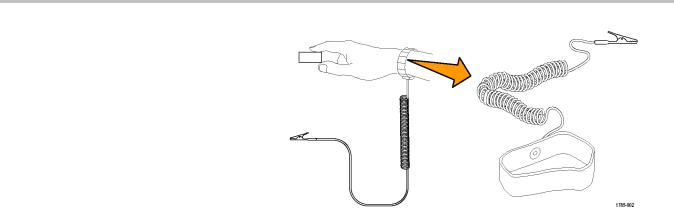
If you are working with static sensitive components, ground yourself. Static electricity that builds up on your body can damage static-sensitive components. Wearing a grounding strap safely sends static charges on your body to earth ground.
12 |
DPO4000 Series User Manual |
 Loading...