


 Loading...
User Manual
SDA 601
Serial Digital Analyzer
070-8913-03
Copyright Tektronix, Inc., 1994. All rights reserved. Printed in U.S.A. Tektronix products are covered by U.S. and foreign patents, issued and pending.
Information in this publication supersedes that in all previously published material. Specifications and price change privileges reserved. The following are registered trademarks: TEKTRONIX and TEK.
For product related information, phone: 800-TEKWIDE (800-835-9433), extension TV.
For further information, contact: Tektronix, Inc., Corporate Offices, P.O. Box 1000, Wilsonville, OR 97070±1000, U.S.A. Phone: (503) 627±7111; TLX: 192825; TWX: (910) 467±8708; Cable:
TEKWSGT.
Warranty
Tektronix warrants that the SDA 601 Serial Digital Analyzer will be free from defects in materials and workmanship for a period of
one (1) year from the date of shipment. If any such product proves defective during this warranty period, Tektronix, at its option, either will repair the defective product without charge for parts and labor, or will provide a replacement in exchange for the defective product.
In order to obtain service under this warranty, Customer must notify Tektronix of the defect before the expiration of the warranty period and make suitable arrangements for the performance of service. Customer shall be responsible for packaging and shipping the defective product to the service center designated by Tektronix, with shipping charges prepaid. Tektronix shall pay for the return of the product to Customer if the shipment is to a location within the country in which the Tektronix service center is located. Customer shall be responsible for paying all shipping charges, duties, taxes, and any other charges for products returned to any other locations.
This warranty shall not apply to any defect, failure or damage caused by improper use or improper or inadequate maintenance and care. Tektronix shall not be obligated to furnish service under this warranty a) to repair damage resulting from attempts by personnel other than Tektronix representatives to install, repair or service the product; b) to repair damage resulting from improper use or connection to incompatible equipment; c) to repair any damage or malfunction caused by the use of non-Tektronix supplies; or d) to service a product that has been modified or integrated with other products when the effect of such modification or integration increases the time or difficulty of servicing the product.
This warranty is given by Tektronix with respect to this product in lieu of any other warranties, expressed or implied. Tektronix and its vendors disclaim any implied warranties of merchantability or fitness for a particular purpose. Tektronix' responsibility to repair or replace defective products is the sole and exclusive remedy provided to the customer for breach of this warranty. Tektronix and its vendors will not be liable for any indirect, special, incidental, or consequential damages irrespective of whether Tektronix or the vendor has advance notice of the possibility of such damages.

EC Declaration of Conformity
We
Tektronix Holland N.V.
Marktweg 73A
8444 AB Heerenveen
The Netherlands
declare under sole responsibility that the
SDA 601 Handheld Serial Digital Analyzer
meets the intent of Directive 89/336/EEC for Electromagnetic Compatibility. Compliance was demonstrated to the following specifications as listed in the Official Journal of the European Communities:
EN 55011 Class A Radiated and Conducted Emissions
EN 50081-1 Emissions:
EN 60555-2 AC Power Line Harmonic Emissions
EN 50082-1 Immunity:
IEC 801-2 Electrostatic Discharge Immunity IEC 801-3 RF Electromagnetic Field Immunity
IEC 801-4 Electrical Fast Transient/Burst Immunity
High-quality shielded cables must be used to ensure compliance to the above listed standards.

Table of Contents
Getting Started . . . . . . . . . . . . . . . . . . . . . . . . . . . . . . . . . . . . . |
1 |
Supplying Power . . . . . . . . . . . . . . . . . . . . . . . . . . . . . . . . . . . . |
2 |
Connecting the SDA 601 . . . . . . . . . . . . . . . . . . . . . . . . . . . . . . |
4 |
SERIAL INPUT . . . . . . . . . . . . . . . . . . . . . . . . . . . . . . . . . . |
4 |
AUX Output . . . . . . . . . . . . . . . . . . . . . . . . . . . . . . . . . . . . . |
4 |
RS-232 Interface . . . . . . . . . . . . . . . . . . . . . . . . . . . . . . . . . |
5 |
Keypad and Display Conventions . . . . . . . . . . . . . . . . . . . . . . . |
7 |
The On-screen Display (OSD) . . . . . . . . . . . . . . . . . . . . . . . . . . |
8 |
Preliminary Settings . . . . . . . . . . . . . . . . . . . . . . . . . . . . . . . . . . |
9 |
Set the Date and Time . . . . . . . . . . . . . . . . . . . . . . . . . . . . . |
9 |
Set the Battery Type . . . . . . . . . . . . . . . . . . . . . . . . . . . . . . . |
10 |
Enable (Disable) Auto Power Off . . . . . . . . . . . . . . . . . . . . |
10 |
Disable (Enable) Timed LCD Backlight Turn Off . . . . . . . |
11 |
Performance Verification . . . . . . . . . . . . . . . . . . . . . . . . . . . . . . |
11 |
Operating Basics . . . . . . . . . . . . . . . . . . . . . . . . . . . . . . . . . . . |
13 |
Using Your SDA 601 . . . . . . . . . . . . . . . . . . . . . . . . . . . . . . . . . |
13 |
Analyzing a Signal . . . . . . . . . . . . . . . . . . . . . . . . . . . . . . . . |
14 |
Watching a Signal . . . . . . . . . . . . . . . . . . . . . . . . . . . . . . . . |
16 |
Alarms . . . . . . . . . . . . . . . . . . . . . . . . . . . . . . . . . . . . . . . . . |
19 |
Displaying the Signal Level . . . . . . . . . . . . . . . . . . . . . . . . . |
21 |
Cursor . . . . . . . . . . . . . . . . . . . . . . . . . . . . . . . . . . . . . . . . . . |
22 |
Highlighting . . . . . . . . . . . . . . . . . . . . . . . . . . . . . . . . . . . . . |
23 |
Pulse Cross . . . . . . . . . . . . . . . . . . . . . . . . . . . . . . . . . . . . . . |
24 |
Presets . . . . . . . . . . . . . . . . . . . . . . . . . . . . . . . . . . . . . . . . . |
25 |
Software Reset . . . . . . . . . . . . . . . . . . . . . . . . . . . . . . . . . . . |
25 |
SDA 601 Serial Digital Analyzer User Manual |
i |

Contents
Reference . . . . . . . . . . . . . . . . . . . . . . . . . . . . . . . . . . . . . . . . . |
27 |
SDA 601 Menus . . . . . . . . . . . . . . . . . . . . . . . . . . . . . . . . . . . . . |
27 |
Menu Conventions . . . . . . . . . . . . . . . . . . . . . . . . . . . . . . . . |
27 |
Watch Menu (groups enabled) . . . . . . . . . . . . . . . . . . . . . . . |
29 |
Watch Menu (items enabled) . . . . . . . . . . . . . . . . . . . . . . . . |
29 |
Alarm Menu . . . . . . . . . . . . . . . . . . . . . . . . . . . . . . . . . . . . . |
30 |
I/O Menu . . . . . . . . . . . . . . . . . . . . . . . . . . . . . . . . . . . . . . . |
31 |
Display Select Menu . . . . . . . . . . . . . . . . . . . . . . . . . . . . . . |
31 |
Presets Menu . . . . . . . . . . . . . . . . . . . . . . . . . . . . . . . . . . . . |
31 |
Utility Menu . . . . . . . . . . . . . . . . . . . . . . . . . . . . . . . . . . . . . |
31 |
The AUX Output . . . . . . . . . . . . . . . . . . . . . . . . . . . . . . . . . . . . |
35 |
RS-232 Connector . . . . . . . . . . . . . . . . . . . . . . . . . . . . . . . . . . . |
35 |
RS-232/Printer Setups . . . . . . . . . . . . . . . . . . . . . . . . . . . . . |
36 |
Using the Watch Mode . . . . . . . . . . . . . . . . . . . . . . . . . . . . . . . |
36 |
Format Error Checking . . . . . . . . . . . . . . . . . . . . . . . . . . . . |
36 |
Using the CRC Change Watch Group . . . . . . . . . . . . . . . . . |
38 |
Appendix A: Characteristics . . . . . . . . . . . . . . . . . . . . . . . . . |
41 |
Safety Standard Compliance . . . . . . . . . . . . . . . . . . . . . . . . . . . |
41 |
Specification Tables . . . . . . . . . . . . . . . . . . . . . . . . . . . . . . . . . . |
42 |
Appendix B: Replaceable Parts . . . . . . . . . . . . . . . . . . . . . . . |
45 |
Appendix C: User Service . . . . . . . . . . . . . . . . . . . . . . . . . . . . |
47 |
Battery Hints . . . . . . . . . . . . . . . . . . . . . . . . . . . . . . . . . . . . . . . |
47 |
The BATTERY LOW Message . . . . . . . . . . . . . . . . . . . . . . |
47 |
Low-battery Shut Down . . . . . . . . . . . . . . . . . . . . . . . . . . . . |
47 |
Replacing the Batteries or Battery Pack . . . . . . . . . . . . . . . |
48 |
Replacing the Touch Memory/Timer Module . . . . . . . . . . . . . . |
49 |
Preventive Maintenance . . . . . . . . . . . . . . . . . . . . . . . . . . . . . . . |
49 |
Glossary . . . . . . . . . . . . . . . . . . . . . . . . . . . . . . . . . . . . . . . . . . |
51 |
Cursor . . . . . . . . . . . . . . . . . . . . . . . . . . . . . . . . . . . . . . . . . . |
1 |
Pulse Cross . . . . . . . . . . . . . . . . . . . . . . . . . . . . . . . . . . . . . . |
3 |
I/O Menu . . . . . . . . . . . . . . . . . . . . . . . . . . . . . . . . . . . . . . . |
4 |
ii |
SDA 601 Serial Digital Analyzer User Manual |

Contents
List of Figures |
|
Figure 1: Opening the Battery Compartment . . . . . . . . . . . . |
2 |
Figure 2: Connecting the SDA 601 . . . . . . . . . . . . . . . . . . . . . |
4 |
Figure 3: A Printed Analysis Report . . . . . . . . . . . . . . . . . . . |
6 |
Figure 4: The Default Watching OSD . . . . . . . . . . . . . . . . . . |
8 |
Figure 5: The Set Time display . . . . . . . . . . . . . . . . . . . . . . . . |
9 |
Figure 6: The Analyze OSD . . . . . . . . . . . . . . . . . . . . . . . . . . |
15 |
Figure 7: The SDA 601 ªWatchingº Display . . . . . . . . . . . . . |
18 |
Figure 8: Watch Errors Reported on the OSD . . . . . . . . . . . |
19 |
Figure 9: The SDA 601 Signal Level Display . . . . . . . . . . . . |
21 |
Figure 10: The Cursor Data Display . . . . . . . . . . . . . . . . . . . |
22 |
Figure 11: SDA 601 Menu Conventions . . . . . . . . . . . . . . . . . |
27 |
Figure 12: The OSD Setups/Horizontal Position Item . . . . . |
28 |
Figure 13: The SDA Number Keys . . . . . . . . . . . . . . . . . . . . |
28 |
Figure 14: The Cursor Data Display . . . . . . . . . . . . . . . . . . . |
1 |
List of Tables |
|
Table 1: RS-232 Connector Pin Assignments . . . . . . . . . . . |
35 |
Table 2: Serial Digital Video Input . . . . . . . . . . . . . . . . . . . . . |
42 |
Table 3: AUX Output . . . . . . . . . . . . . . . . . . . . . . . . . . . . . . . |
42 |
Table 4: Signal Level Meter . . . . . . . . . . . . . . . . . . . . . . . . . . |
43 |
Table 5: Physical Characteristics . . . . . . . . . . . . . . . . . . . . . |
43 |
Table 6: Environmental Characteristics . . . . . . . . . . . . . . . . |
43 |
SDA 601 Serial Digital Analyzer User Manual |
iii |

Contents
iv |
SDA 601 Serial Digital Analyzer User Manual |
General Safety Summary
Review the following safety precautions to avoid injury and prevent damage to this product or any products connected to it. To avoid potential hazards, use this product only as specified.
Only qualified personnel should perform service procedures.
To Avoid Fire or Personal Injury
Observe All Terminal Ratings. To avoid fire or shock hazard, observe all ratings and markings on the product. Consult the product manual for further ratings information before making connections to the product.
The common terminal is at ground potential. Do not connect the common terminal to elevated voltages.
Connect the ground lead of the probe to earth ground only.
Replace Batteries Properly. Replace batteries only with the proper type and rating specified.
Recharge Batteries Properly. Recharge batteries for the recommended charge cycle only.
Use Proper AC Adapter. Use only the AC adapter specified for this product.
Do Not Operate With Suspected Failures. If you suspect there is damage to this product, have it inspected by qualified service personnel.
Do Not Operate in Wet/Damp Conditions.
Do Not Operate in an Explosive Atmosphere.
SDA 601 Serial Digital Analyzer User Manual |
v |
General Safety Summary
Safety Terms and Symbols
Terms in This Manual. These terms may appear in this manual:
WARNING. Warning statements identify conditions or practices that could result in injury or loss of life.
CAUTION. Caution statements identify conditions or practices that could result in damage to this product or other property.
Terms on the Product. These terms may appear on the product:
DANGER indicates an injury hazard immediately accessible as you read the marking.
WARNING indicates an injury hazard not immediately accessible as you read the marking.
CAUTION indicates a hazard to property including the product.
Symbols on the Product. These symbols may appear on the product:
CAUTION |
Double |
Refer to Manual |
Insulated |
Battery Recycling
This product contains a Nickel Cadmium (NiCd) battery, which must be recycled or disposed of properly. For the location of a local battery recycler in the U.S. or Canada, please contact:
RBRC |
(800) BATTERY |
Rechargeable Battery Recycling Corp. |
(800) 227-7379 |
P.O. Box 141870 |
www.rbrc.com |
Gainesville, Florida 32614 |
|
vi |
SDA 601 Serial Digital Analyzer User Manual |
Getting Started
Please read the following statements before using your new SDA 601 Serial Digital Analyzer. See the rest of this section for tips on supplying power, making preliminary settings, and connecting the instrument.
WARNING. Install or replace batteries only with the instrument switched OFF and the AC adapter disconnected. Electrical shock or equipment damage can result.
CAUTION. Do not attempt to operate the SDA 601 with an improper AC adapter. Damage to the instrument can result.
For best results, use the AC adapter supplied with the instrument. If the supplied adapter is incorrect for the local AC power supply, contact your nearest Tektronix representative.
The adapter voltage must be 9 to 15 VDC with an open-circuit voltage less than 18 VDC; the adapter connector must have the negative (±) polarity contact in the center.
NOTE. Internal batteries are recommended when using an external power adapter. A loose adapter connector can cause the loss of some user settings and unexpected results the next time the instrument is powered on.
The battery type, disposable or rechargeable, must be selected using through the Utility menu (see page 10). Failure to select the proper battery type can result in damage to the batteries and product.
Replace the batteries only with standard AA batteries (1.2±1.5 V, nominal), or the Tektronix rechargeable battery pack listed on page 45.
For more information, please contact your nearest Tektronix representative or field office. In the United States and Canada, you can also call the Tektronix information number, 1-800-TEK-WIDE (1-800-835-9433), between 8:00 am and 5:00 pm Pacific time.
SDA 601 Serial Digital Analyzer User Manual |
1 |
Getting Started
Supplying Power
The SDA 601 is DC powered. You may power it with the standard AC adapter, the optional 9.6 V NiCad battery pack, eight standard AA batteries, or a ªBPº type battery pack with the correct voltage and polarity. The external DC power connector is on the left side of the instrument.
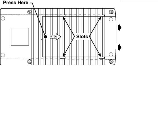
Figure 1: Opening the Battery Compartment
To install AA batteries or the battery pack, open the battery compartment of the SDA 601 by pressing down on the cover and sliding it in the direction of the inscribed arrow, as shown above. When the cover tabs line up with the slots in the case, lift the cover away from the instrument. Install batteries in alternating directions as indicated by the graphic molded into the ªfloorº of the battery compartment. If using the optional battery pack, take the time to identify both contacts and install the pack properly.
When selecting a power source for your SDA 601, please remember:
HAttempting to use an improper AC adapter can cause permanent damage to the instrument. USE AN APPROPRIATE DC POWER SOURCE ONLY: Voltage must be between 9 and 15 VDC; the center contact of the connector must be NEGATIVE polarity; and open-circuit voltage must not exceed 18 VDC. For best results, use the adapter supplied with the instrument.
HThere is no need to remove the optional NiCad battery pack for recharging. The SDA 601 will ªtrickle chargeº the battery pack whenever the standard AC adapter is attached and the instrument
2 |
SDA 601 Serial Digital Analyzer User Manual |

Getting Started
is switched off. It can take up to 16 hours to fully charge the battery pack. Note that charging will occur only if the adapter supplies at least 12 V; make sure that the adapter you use is appropriate for the local AC supply.
HAA batteries are not included with the instrument; buy them locally. Rechargeable AA batteries may be used, but they are NOT recharged automatically. To recharge AA batteries, remove them from the instrument and use an appropriate charger. For safety, read and follow the battery charger instructions. Do NOT attempt to recharge standard alkaline batteries.
HAfter three minutes with no key press, the LCD back light will be dimmed to save battery charge. (This may be disabled through the Utility/Diagnostics/Power Manage menu; see page 33.)
HTo guard against battery discharge if you forget to turn the
SDA 601 off, enable Auto Power Off through the Utility/Diagnostics/Power Manage menu (see page 10).
HThe SDA 601 can sense low battery voltage. It will warn you when the charge is sufficient for approximately ten more minutes of operation. The instrument will shut itself down when the battery voltage becomes too low for reliable operation. See the Battery hints in Appendix C, beginning on page 47.
The ON key toggles instrument power On and Off.
NOTE. If the instrument is operating with low batteries, it may turn itself off and on. The batteries should be replaced or recharged depending on battery types.
SDA 601 Serial Digital Analyzer User Manual |
3 |
Getting Started
Connecting the SDA 601
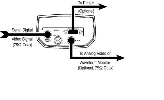
Figure 2: Connecting the SDA 601
Connect the instrument as shown in Figure 2. The OPTION connector is reserved for later versions of the instrument. Note that the SDA 601 has many capabilities and features, and you may wish to gain familiarity with it by first connecting it directly to a serial digital, component video signal generator such as the Tektronix TSG 601, an analog video monitor, andÐif convenientÐa compact printer, such as the SeikoDPU 411 printer (Tektronix part number 119-4594-00), available from Tektronix distributors and through TekDirect.
SERIAL INPUT
Connect the instrument to your system through the SERIAL INPUT with 75 coaxial cable. Note that the SDA 601 has internal, active termination. The signal path that ends with the SDA will be properly terminated only when the instrument is switched on.
AUX Output
HLets you view the picture for convenient source identification.
HCan contain the On-screen Display (OSD; see page 8), which shows the most recent Watch or Analyze results one page at a timeÐinstead of one item at a time as on the SDA 601 display.
4 |
SDA 601 Serial Digital Analyzer User Manual |

Getting Started
HWith Pulse Cross enabled (see page 24), lets you ªseeº the contents of the vertical and horizontal interval portions of the serial video signal.
HCan include Cursor cross hairs for convenient positioning of the Cursors (see page 22).
HWhen Highlighting (see page 23) is turned on, can help you locate and identify errors in the picture, or the digital encoding of the signal.
The AUX output signal may be thought of as ªpseudo video.º It is derived from the serial input signal, converted to analog by an unfiltered 5-bit DAC. The signal can be the Y, R±Y, or B±Y component. Please see page 35 for more information about the AUX output.
RS-232 Interface
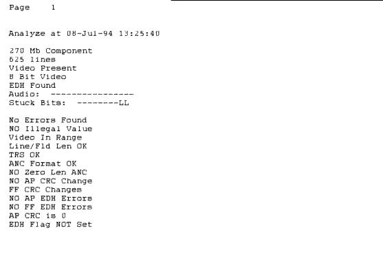
Connect an ASCII, serial printer to the RS-232 connector to create ªhard copyº analysis reports, or to log errors detected during a Watch session. See page 35 for the connector pinouts, and other necessary communications settings. With a printer connected, you can chooseÐthrough the Alarm menuÐto have the SDA 601 log every error as it occurs, or to print a Watch report every ten seconds. This will permit unattended monitoring of your system. See page 20 for more information.
To test your printer connection and settings, perform a signal analysis by pressing Analyze. Then, press Shift-Analyze. The printer should respond by printing an analysis report that resembles the one shown in Figure 3.
SDA 601 Serial Digital Analyzer User Manual |
5 |
Getting Started
Figure 3: A Printed Analysis Report
The RS-232 interface is also designed to support in-field upgrade of the operating software. Information regarding any such upgrades will be available from your Tektronix representative or field office.
6 |
SDA 601 Serial Digital Analyzer User Manual |

Getting Started
Keypad and Display Conventions
Please see the Instruction card (p/n 070-8912-00) supplied with your SDA 601 for a ªtourº of the keypad and an explanation of the display symbols. For your convenience, the following panels are taken from the card.
SDA 601 Serial Digital Analyzer User Manual |
7 |
Getting Started
The On-screen Display (OSD)
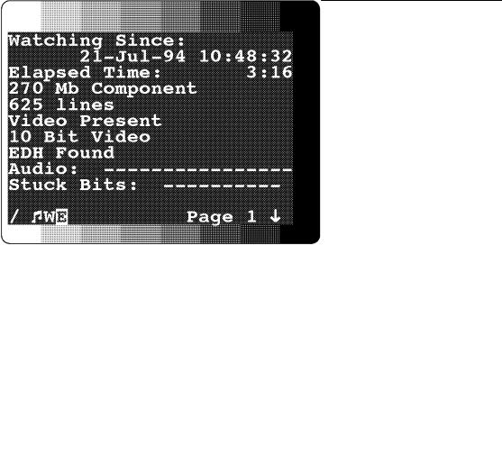
The OSD is a 12 line, 24 column display containing results from an SDA 601 Analyze or Watch session. It can be superimposed on the AUX output and viewed on an attached video monitor. Toggle the OSD On/Off with the Insert On/Off key. The default OSD will resemble Figure 4 when the instrument is in Watch mode. You can control several OSD characteristics (size, color, screen position) through the Utility/OSD Setups submenu; see page 32.
Figure 4: The Default Watching OSD
The symbols on the bottom line of the OSD have the following meanings:
HThe rotating line in the lower left indicates that Auto Power Off is enabled.
HThe musical note symbol indicates that Alarms are toggled On with the Alarm key or through the Alarm menu. This symbol can appear even when the beeper and print errors items in the Alarm menu are set to Off.
HThe ªWº appears when the instrument is in Watch mode.
HThe reversed ªEº means that an error is detected.
8 |
SDA 601 Serial Digital Analyzer User Manual |
Getting Started
HSimilar reversed ªSº and ªSLº icons (not shown) will appear when SDA 601 keypad is shifted and shift locked.
HThe down arrow in the lower right indicates that the B key may be used to reveal another page. An up arrow will appear if the Y key may be used.
The Analyze OSD is similar; see Figure 6, on page 15.
Preliminary Settings
Once the SDA 601 is up and running, you should choose some settings depending on how you'll be using the instrument. These settings are made through the Utility menu. Invoke the Utility menu by holding Lock Out down while pressing the ON key (when the LCD says ªWatchingº or ªIdleº). Then follow these directions to set the Battery Type and enable Auto Power Down (if desired).
Set the Date and Time
1.Once in the Utility menu, use the Y and B keys to scroll to the Set Time item, and press Enter. The instrument display will change to resemble Figure 5.
Figure 5: The Set Time display
2.The underline cursor indicates the active character position. Move the cursor with the A and " keys. Enter the appropriate character from the SDA 601 keypad. When the cursor is in positions that require numeric entry, the keys will be automatically shifted. When you enter an appropriate character for the field, the cursor will move one position to the right. The acceptable month abbreviations are the first three characters of the English name: JAN; FEB; MAR; APR; MAY; JUN; JUL; AUG; SEP; OCT; NOV; DEC.
SDA 601 Serial Digital Analyzer User Manual |
9 |

Getting Started
Enter the time in 24 hour format; that is, if the present time is 4:15 pm, enter 16:15.
3.When the correct date and time is shown on the display, press Enter. If all values are valid, the instrument will respond with the message ªTime Accepted.º If you have made an error and entered an invalid date or time, the instrument will respond with an appropriate error message. If that happens, correct the error and press enter.
4.Press any rectangular key to exit the Utility menu, or proceed to other preliminary settings, as appropriate.
Set the Battery Type
1.After setting the clock, press the B key once to scroll to the Diagnostics submenu item, and press Enter.
2.In the Diagnostics submenu, scroll down to the Power Manage item with the B key. Again, press Enter.
3.The top item in the Power Manage submenu is Battery Type. Toggle to the selection that matches the type of battery you have installed in your SDA 601 by pressing either A or ". The choices are ªrechargeableº and ªdisposable.º Select rechargeable when using NiCad AA cells or the optional battery pack; choose disposable when you are using common Alkaline AA batteries, which cannot be recharged. Press Enter to confirm the choice.
4.When the correct battery type is indicated by an asterisk (*) on the lower right of the LCD, continue to Auto Power Off, or press any rectangular key to exit the Utility/Diagnostics/Power Manage submenu and return to normal operation.
Enable (Disable) Auto Power Off
ªAuto Power Offº will switch the instrument off when ten minutes have passed without a key press. Enable this feature when you are using battery power and operating in an environment in which unplanned shutdown of the SDA 601 is permissible.
1.While still in the Utility/Diagnostics/Power Manage submenu, press the B key twice to scroll to the Auto Power Off item.
10 |
SDA 601 Serial Digital Analyzer User Manual |

Getting Started
2.Disable/enable Auto Power Off by pressing either A or ". Press Enter to confirm the choice. Enabled Auto Power Down is indicated by a ªrotating lineº symbol on the second line of the instrument display, and in the lower-left corner of the OSD.
3.Use the Y and B keys to scroll to other ªpower manageº items, or press any rectangular key to exit the menu and resume normal operation.
Disable (Enable) Timed LCD Backlight Turn Off
Another power saving feature of the SDA 601 is timed turn-off of the LCD backlight. It is enabled by default in a new or reset instrument. If you will always operate with the AC adapter, you may wish to disable the feature. To toggle backlight turn-off:
1.In the Utility/Diagnostics/Power Manage submenu, use the Y and B keys to scroll to the LCD Backlight item.
2.Choose between ªTimed Turn Offº and ªOn all the timeº with either A or ", then press Enter to confirm the choice.
3.As before, use the Y and B keys to scroll to other ªpower manageº items, or press any rectangular key to exit the menu and resume normal operation.
Performance Verification
A performance verification procedure, which some users may require for acceptance testing, is included in the optional SDA 601 service manual (Tek p/n 070-8914-0x). To order a service manual, please contact your nearest Tektronix representative or field office.
SDA 601 Serial Digital Analyzer User Manual |
11 |

Getting Started
12 |
SDA 601 Serial Digital Analyzer User Manual |
Loading...