


 Loading...
Tektronix TDS2004, TDS1001, TDS2024, TDS2022, TDS2014 Service Manual
...Service Manual
TDS1000 and TDS2000 Series
Digital Storage Oscilloscopes
071-1076-02
This document supports firmware version 1.00 and above.
Warning
The servicing instructions are for use by qualified personnel only. To avoid personal injury, do not perform any servicing unless you are qualified to do so. Refer to all safety summaries prior to performing service.
www.tektronix.com
Copyright © Tektronix, Inc. All rights reserved. Licensed software products are owned by Tektronix or its subsidiaries or suppliers, and are protected by national copyright laws and international treaty provisions.
Tektronix products are covered by U.S. and foreign patents, issued and pending. Information in this publication supercedes that in all previously published material. Specifications and price change privileges reserved.
TEKTRONIX and TEK are registered trademarks of Tektronix, Inc.
Contacting Tektronix
Tektronix, Inc.
14200 SW Karl Braun Drive
P.O. Box 500
Beaverton, OR 97077
USA
For product information, sales, service, and technical support:
HIn North America, call 1-800-833-9200.
HWorldwide, visit www.tektronix.com to find contacts in your area.
Warranty 16
Tektronix warrants that the product will be free from defects in materials and workmanship for a period of three
(3) years from the date of original purchase from an authorized Tektronix distributor. If the product proves defective during this warranty period, Tektronix, at its option, either will repair the defective product without charge for parts and labor, or will provide a replacement in exchange for the defective product. Batteries are excluded from this warranty. Parts, modules and replacement products used by Tektronix for warranty work may be new or reconditioned to like new performance. All replaced parts, modules and products become the property of Tektronix.
In order to obtain service under this warranty, Customer must notify Tektronix of the defect before the expiration of the warranty period and make suitable arrangements for the performance of service. Customer shall be responsible for packaging and shipping the defective product to the service center designated by Tektronix, shipping charges prepaid, and with a copy of customer proof of purchase. Tektronix shall pay for the return of the product to Customer if the shipment is to a location within the country in which the Tektronix service center is located. Customer shall be responsible for paying all shipping charges, duties, taxes, and any other charges for products returned to any other locations.
This warranty shall not apply to any defect, failure or damage caused by improper use or improper or inadequate maintenance and care. Tektronix shall not be obligated to furnish service under this warranty a) to repair damage resulting from attempts by personnel other than Tektronix representatives to install, repair or service the product; b) to repair damage resulting from improper use or connection to incompatible equipment; c) to repair any damage or malfunction caused by the use of non-Tektronix supplies; or d) to service a product that has been modified or integrated with other products when the effect of such modification or integration increases the time or difficulty of servicing the product.
THIS WARRANTY IS GIVEN BY TEKTRONIX WITH RESPECT TO THE PRODUCT IN LIEU OF ANY OTHER WARRANTIES, EXPRESS OR IMPLIED. TEKTRONIX AND ITS VENDORS DISCLAIM ANY IMPLIED WARRANTIES OF MERCHANTABILITY OR FITNESS FOR A PARTICULAR PURPOSE. TEKTRONIX’ RESPONSIBILITY TO REPAIR OR REPLACE DEFECTIVE PRODUCTS IS THE SOLE AND EXCLUSIVE REMEDY PROVIDED TO THE CUSTOMER FOR BREACH OF THIS WARRANTY. TEKTRONIX AND ITS VENDORS WILL NOT BE LIABLE FOR ANY INDIRECT, SPECIAL, INCIDENTAL, OR CONSEQUENTIAL DAMAGES IRRESPECTIVE OF WHETHER TEKTRONIX OR THE VENDOR HAS ADVANCE NOTICE OF THE POSSIBILITY OF SUCH DAMAGES.

Table of Contents
General Safety Summary . . . . . . . . . . . . . . . . . . . . . . . . . . . . . . . . . . . |
vii |
Service Safety Summary . . . . . . . . . . . . . . . . . . . . . . . . . . . . . . . . . . . . |
ix |
Environmental Considerations . . . . . . . . . . . . . . . . . . . . . . . . . . . . . . . |
xi |
Preface . . . . . . . . . . . . . . . . . . . . . . . . . . . . . . . . . . . . . . . . . . . . . . . . . . . |
xiii |
Related Manuals . . . . . . . . . . . . . . . . . . . . . . . . . . . . . . . . . . . . . . . . . . . . . . . . . |
xiii |
Specifications |
|
Certifications and Compliances . . . . . . . . . . . . . . . . . . . . . . . . . . . . . . . . . . . . . |
1-8 |
Operating Information |
|
General Features . . . . . . . . . . . . . . . . . . . . . . . . . . . . . . . . . . . . . . . . . . . . . . . . . |
2-2 |
Installation . . . . . . . . . . . . . . . . . . . . . . . . . . . . . . . . . . . . . . . . . . . . . . . . . . . . . . |
2-4 |
Power Cord . . . . . . . . . . . . . . . . . . . . . . . . . . . . . . . . . . . . . . . . . . . . . . . . . |
2-4 |
Security Loop . . . . . . . . . . . . . . . . . . . . . . . . . . . . . . . . . . . . . . . . . . . . . . . . |
2-4 |
Extension Modules . . . . . . . . . . . . . . . . . . . . . . . . . . . . . . . . . . . . . . . . . . . . . . . |
2-5 |
Functional Check . . . . . . . . . . . . . . . . . . . . . . . . . . . . . . . . . . . . . . . . . . . . . . . . |
2-6 |
Self Calibration . . . . . . . . . . . . . . . . . . . . . . . . . . . . . . . . . . . . . . . . . . . . . . . . . . |
2-7 |
Default Setup . . . . . . . . . . . . . . . . . . . . . . . . . . . . . . . . . . . . . . . . . . . . . . . . . . . |
2-7 |
Theory of Operation |
|
Main Board . . . . . . . . . . . . . . . . . . . . . . . . . . . . . . . . . . . . . . . . . . . . . . . . . . . . . |
3-4 |
Acquisition System . . . . . . . . . . . . . . . . . . . . . . . . . . . . . . . . . . . . . . . . . . . |
3-4 |
Processing and Display System . . . . . . . . . . . . . . . . . . . . . . . . . . . . . . . . . . |
3-5 |
Input Signal Interface . . . . . . . . . . . . . . . . . . . . . . . . . . . . . . . . . . . . . . . . . . |
3-5 |
Probe Compensation . . . . . . . . . . . . . . . . . . . . . . . . . . . . . . . . . . . . . . . . . . |
3-5 |
External Trigger . . . . . . . . . . . . . . . . . . . . . . . . . . . . . . . . . . . . . . . . . . . . . . |
3-5 |
Main Board Power . . . . . . . . . . . . . . . . . . . . . . . . . . . . . . . . . . . . . . . . . . . . |
3-5 |
Power Supply . . . . . . . . . . . . . . . . . . . . . . . . . . . . . . . . . . . . . . . . . . . . . . . . . . . |
3-6 |
Display Module . . . . . . . . . . . . . . . . . . . . . . . . . . . . . . . . . . . . . . . . . . . . . . . . . . |
3-6 |
Front Panel . . . . . . . . . . . . . . . . . . . . . . . . . . . . . . . . . . . . . . . . . . . . . . . . . . . . . |
3-6 |
Two-Channel Oscilloscopes . . . . . . . . . . . . . . . . . . . . . . . . . . . . . . . . . . . . . |
3-6 |
Four-Channel Oscilloscopes . . . . . . . . . . . . . . . . . . . . . . . . . . . . . . . . . . . . |
3-7 |
LEDs . . . . . . . . . . . . . . . . . . . . . . . . . . . . . . . . . . . . . . . . . . . . . . . . . . . . . . |
3-7 |
Extension Modules . . . . . . . . . . . . . . . . . . . . . . . . . . . . . . . . . . . . . . . . . . . . . . . |
3-7 |
Performance Verification |
|
Required Equipment . . . . . . . . . . . . . . . . . . . . . . . . . . . . . . . . . . . . . . . . . . . . . . |
4-1 |
Test Record . . . . . . . . . . . . . . . . . . . . . . . . . . . . . . . . . . . . . . . . . . . . . . . . . . . . . |
4-2 |
Performance Verification Procedures . . . . . . . . . . . . . . . . . . . . . . . . . . . . . . . . . |
4-3 |
TDS1000 and TDS2000 Series Digital Storage Oscilloscopes Service Manual |
i |

Table of Contents
Self Test . . . . . . . . . . . . . . . . . . . . . . . . . . . . . . . . . . . . . . . . . . . . . . . . . . . . |
4-3 |
Self Calibration . . . . . . . . . . . . . . . . . . . . . . . . . . . . . . . . . . . . . . . . . . . . . . |
4-3 |
Check DC Gain Accuracy . . . . . . . . . . . . . . . . . . . . . . . . . . . . . . . . . . . . . . |
4-3 |
Check Bandwidth . . . . . . . . . . . . . . . . . . . . . . . . . . . . . . . . . . . . . . . . . . . . . |
4-5 |
Check Sample Rate and Delay Time Accuracy . . . . . . . . . . . . . . . . . . . . . . |
4-6 |
Check Edge Trigger Sensitivity . . . . . . . . . . . . . . . . . . . . . . . . . . . . . . . . . . |
4-7 |
Check External Edge Trigger Sensitivity . . . . . . . . . . . . . . . . . . . . . . . . . . . |
4-9 |
Adjustment Procedures |
|
Required Equipment . . . . . . . . . . . . . . . . . . . . . . . . . . . . . . . . . . . . . . . . . . . . . . |
5-1 |
Adjustment Procedure . . . . . . . . . . . . . . . . . . . . . . . . . . . . . . . . . . . . . . . . . . . . . |
5-3 |
Enable the Service Menu . . . . . . . . . . . . . . . . . . . . . . . . . . . . . . . . . . . . . . . |
5-3 |
Adjustment Procedure . . . . . . . . . . . . . . . . . . . . . . . . . . . . . . . . . . . . . . . . . |
5-5 |
Maintenance |
|
Preparation . . . . . . . . . . . . . . . . . . . . . . . . . . . . . . . . . . . . . . . . . . . . . . . . . . . . . |
6-1 |
Preventing ESD . . . . . . . . . . . . . . . . . . . . . . . . . . . . . . . . . . . . . . . . . . . . . . . . . . |
6-1 |
Inspection and Cleaning . . . . . . . . . . . . . . . . . . . . . . . . . . . . . . . . . . . . . . . . . . . |
6-2 |
General Care . . . . . . . . . . . . . . . . . . . . . . . . . . . . . . . . . . . . . . . . . . . . . . . . |
6-2 |
Inspection and Cleaning Procedures . . . . . . . . . . . . . . . . . . . . . . . . . . . . . . |
6-2 |
Removal and Installation Procedures . . . . . . . . . . . . . . . . . . . . . . . . . . . . . . . . . |
6-5 |
Preparation . . . . . . . . . . . . . . . . . . . . . . . . . . . . . . . . . . . . . . . . . . . . . . . . . . |
6-5 |
List of Modules . . . . . . . . . . . . . . . . . . . . . . . . . . . . . . . . . . . . . . . . . . . . . . |
6-5 |
Summary of Procedures . . . . . . . . . . . . . . . . . . . . . . . . . . . . . . . . . . . . . . . . |
6-6 |
Required Tools . . . . . . . . . . . . . . . . . . . . . . . . . . . . . . . . . . . . . . . . . . . . . . . |
6-6 |
Rear Feet . . . . . . . . . . . . . . . . . . . . . . . . . . . . . . . . . . . . . . . . . . . . . . . . . . . |
6-7 |
Flip Feet . . . . . . . . . . . . . . . . . . . . . . . . . . . . . . . . . . . . . . . . . . . . . . . . . . . . |
6-9 |
Front-Panel Knobs . . . . . . . . . . . . . . . . . . . . . . . . . . . . . . . . . . . . . . . . . . . . |
6-10 |
Power Button . . . . . . . . . . . . . . . . . . . . . . . . . . . . . . . . . . . . . . . . . . . . . . . . |
6-10 |
Rear Case . . . . . . . . . . . . . . . . . . . . . . . . . . . . . . . . . . . . . . . . . . . . . . . . . . . |
6-10 |
Front Feet . . . . . . . . . . . . . . . . . . . . . . . . . . . . . . . . . . . . . . . . . . . . . . . . . . . |
6-14 |
Power Supply Module . . . . . . . . . . . . . . . . . . . . . . . . . . . . . . . . . . . . . . . . . |
6-15 |
Internal Assembly . . . . . . . . . . . . . . . . . . . . . . . . . . . . . . . . . . . . . . . . . . . . |
6-17 |
Display Cable . . . . . . . . . . . . . . . . . . . . . . . . . . . . . . . . . . . . . . . . . . . . . . . . |
6-19 |
Front-Panel Cable . . . . . . . . . . . . . . . . . . . . . . . . . . . . . . . . . . . . . . . . . . . . |
6-21 |
Main Board Module . . . . . . . . . . . . . . . . . . . . . . . . . . . . . . . . . . . . . . . . . . . |
6-22 |
Display Module . . . . . . . . . . . . . . . . . . . . . . . . . . . . . . . . . . . . . . . . . . . . . . |
6-24 |
Front-Panel Module . . . . . . . . . . . . . . . . . . . . . . . . . . . . . . . . . . . . . . . . . . . |
6-26 |
Keypad . . . . . . . . . . . . . . . . . . . . . . . . . . . . . . . . . . . . . . . . . . . . . . . . . . . . . |
6-28 |
Front Case . . . . . . . . . . . . . . . . . . . . . . . . . . . . . . . . . . . . . . . . . . . . . . . . . . |
6-30 |
ii |
TDS1000 and TDS2000 Series Digital Storage Oscilloscopes Service Manual |

Table of Contents
Troubleshooting . . . . . . . . . . . . . . . . . . . . . . . . . . . . . . . . . . . . . . . . . . . . . . . . . |
6-31 |
Adjustment After Repair . . . . . . . . . . . . . . . . . . . . . . . . . . . . . . . . . . . . . . . |
6-31 |
Required Tools and Equipment . . . . . . . . . . . . . . . . . . . . . . . . . . . . . . . . . . |
6-31 |
Troubleshooting Tree . . . . . . . . . . . . . . . . . . . . . . . . . . . . . . . . . . . . . . . . . . |
6-31 |
PROBE COMP Output . . . . . . . . . . . . . . . . . . . . . . . . . . . . . . . . . . . . . . . . |
6-35 |
Troubleshooting the Power Supply . . . . . . . . . . . . . . . . . . . . . . . . . . . . . . . |
6-35 |
Troubleshooting the Display . . . . . . . . . . . . . . . . . . . . . . . . . . . . . . . . . . . . |
6-36 |
Troubleshooting the Backlight . . . . . . . . . . . . . . . . . . . . . . . . . . . . . . . . . . . |
6-38 |
Troubleshooting the Front Panel . . . . . . . . . . . . . . . . . . . . . . . . . . . . . . . . . |
6-40 |
Troubleshooting the Main Board . . . . . . . . . . . . . . . . . . . . . . . . . . . . . . . . . |
6-43 |
Running Diagnostics . . . . . . . . . . . . . . . . . . . . . . . . . . . . . . . . . . . . . . . . . . |
6-43 |
Troubleshooting Input Connections . . . . . . . . . . . . . . . . . . . . . . . . . . . . . . . |
6-43 |
Using the Error Log . . . . . . . . . . . . . . . . . . . . . . . . . . . . . . . . . . . . . . . . . . . |
6-44 |
Repackaging Instructions . . . . . . . . . . . . . . . . . . . . . . . . . . . . . . . . . . . . . . . . . . |
6-46 |
Packaging . . . . . . . . . . . . . . . . . . . . . . . . . . . . . . . . . . . . . . . . . . . . . . . . . . . |
6-46 |
Storage . . . . . . . . . . . . . . . . . . . . . . . . . . . . . . . . . . . . . . . . . . . . . . . . . . . . . |
6-46 |
Diagrams
Replaceable Parts
Parts Ordering Information . . . . . . . . . . . . . . . . . . . . . . . . . . . . . . . . . . . . . . . . . |
8-1 |
Module Servicing . . . . . . . . . . . . . . . . . . . . . . . . . . . . . . . . . . . . . . . . . . . . . |
8-1 |
Using the Replaceable Parts List . . . . . . . . . . . . . . . . . . . . . . . . . . . . . . . . . . . . . |
8-2 |
Abbreviations . . . . . . . . . . . . . . . . . . . . . . . . . . . . . . . . . . . . . . . . . . . . . . . . |
8-2 |
Mfr. Code to Manufacturer Cross Index . . . . . . . . . . . . . . . . . . . . . . . . . . . |
8-3 |
TDS1000 and TDS2000 Series Digital Storage Oscilloscopes Service Manual |
iii |

Table of Contents
List of Figures
Figure 2-1: Routing the power cord and security cable . . . . . . . . . . |
2-4 |
Figure 2-2: Installing and removing an extension module . . . . . . . . |
2-5 |
Figure 3-1: Module-level block diagram (two channel) . . . . . . . . . . |
3-2 |
Figure 3-2: Module-level block diagram (four channel) . . . . . . . . . . |
3-3 |
Figure 5-1: Adjustment setups . . . . . . . . . . . . . . . . . . . . . . . . . . . . . . . |
5-4 |
Figure 6-1: Removing the rear feet . . . . . . . . . . . . . . . . . . . . . . . . . . . |
6-7 |
Figure 6-2: Installing the rear feet . . . . . . . . . . . . . . . . . . . . . . . . . . . . |
6-8 |
Figure 6-3: Removing and installing the flip feet . . . . . . . . . . . . . . . . |
6-9 |
Figure 6-4: Removing and installing the rear case . . . . . . . . . . . . . . |
6-11 |
Figure 6-5: Aligning the oscilloscope rear case . . . . . . . . . . . . . . . . . |
6-13 |
Figure 6-6: Removing and installing the front feet . . . . . . . . . . . . . . |
6-14 |
Figure 6-7: Removing the power supply module . . . . . . . . . . . . . . . . |
6-15 |
Figure 6-8: Installing the power supply module . . . . . . . . . . . . . . . . |
6-16 |
Figure 6-9: Removing and installing the internal assembly . . . . . . . |
6-17 |
Figure 6-10: Removing the display cable . . . . . . . . . . . . . . . . . . . . . . |
6-19 |
Figure 6-11: Installing the display cable . . . . . . . . . . . . . . . . . . . . . . . |
6-20 |
Figure 6-12: Removing and installing the front-panel cable . . . . . . . |
6-21 |
Figure 6-13: Main board removal . . . . . . . . . . . . . . . . . . . . . . . . . . . . |
6-23 |
Figure 6-14: Removing the display module . . . . . . . . . . . . . . . . . . . . |
6-24 |
Figure 6-15: Installing the display module . . . . . . . . . . . . . . . . . . . . . |
6-25 |
Figure 6-16: Removing the front-panel module . . . . . . . . . . . . . . . . . |
6-26 |
Figure 6-17: Installing the front-panel module . . . . . . . . . . . . . . . . . |
6-27 |
Figure 6-18: Removing and installing the keypad . . . . . . . . . . . . . . . |
6-28 |
Figure 6-19: Oscilloscope troubleshooting tree (1 of 3) . . . . . . . . . . . |
6-32 |
Figure 6-20: Oscilloscope troubleshooting tree (2 of 3) . . . . . . . . . . . |
6-33 |
Figure 6-21: Oscilloscope troubleshooting tree (3 of 3) . . . . . . . . . . . |
6-34 |
Figure 6-22: Measuring the backlight voltage . . . . . . . . . . . . . . . . . . |
6-39 |
Figure 7-1: TDS1000 and TDS2000 series block diagram . . . . . . . . |
7-2 |
Figure 8-1: Exploded diagram . . . . . . . . . . . . . . . . . . . . . . . . . . . . . . . |
8-7 |
iv |
TDS1000 and TDS2000 Series Digital Storage Oscilloscopes Service Manual |

Table of Contents
List of Tables
Table 1-1: Oscilloscope specifications . . . . . . . . . . . . . . . . . . . . . . . . |
1-1 |
Table 1-2: Oscilloscope general specifications . . . . . . . . . . . . . . . . . . |
1-7 |
Table 2-1: Default settings . . . . . . . . . . . . . . . . . . . . . . . . . . . . . . . . . . |
2-7 |
Table 5-1: Required equipment . . . . . . . . . . . . . . . . . . . . . . . . . . . . . |
5-1 |
Table 5-2: Adjustment steps . . . . . . . . . . . . . . . . . . . . . . . . . . . . . . . . |
5-6 |
Table 6-1: Internal inspection check list . . . . . . . . . . . . . . . . . . . . . . |
6-3 |
Table 6-2: List of procedures . . . . . . . . . . . . . . . . . . . . . . . . . . . . . . . . |
6-6 |
Table 6-3: List of error codes . . . . . . . . . . . . . . . . . . . . . . . . . . . . . . . |
6-44 |
Table 8-1: Parts list column descriptions . . . . . . . . . . . . . . . . . . . . . . |
8-2 |
Table 8-2: Manufacturers cross index . . . . . . . . . . . . . . . . . . . . . . . . |
8-3 |
Table 8-3: Replaceable parts list . . . . . . . . . . . . . . . . . . . . . . . . . . . . . |
8-4 |
Table 8-4: Replaceable standard accessories . . . . . . . . . . . . . . . . . . . |
8-8 |
Table 8-5: Replaceable optional accessories . . . . . . . . . . . . . . . . . . . |
8-8 |
TDS1000 and TDS2000 Series Digital Storage Oscilloscopes Service Manual |
v |

Table of Contents
vi |
TDS1000 and TDS2000 Series Digital Storage Oscilloscopes Service Manual |
General Safety Summary
Review the following safety precautions to avoid injury and prevent damage to this product or any products connected to it.
Only qualified personnel should perform service procedures.
Injury Precautions Use Proper Power Cord. To avoid fire hazard, use only the power cord specified for this product.
Avoid Electric Overload. To avoid electric shock or fire hazard, do not apply a voltage to a terminal that is outside the range specified for that terminal.
Avoid Overvoltage. To avoid electric shock or fire hazard, do not apply potential to any terminal, including the common terminal, that varies from ground by more than the maximum rating for that terminal.
Avoid Electric Shock. To avoid injury or loss of life, do not connect or disconnect probes or test leads while they are connected to a voltage source.
Ground the Product. This product is grounded through the grounding conductor of the power cord. To avoid electric shock, the grounding conductor must be connected to earth ground. Before making connections to the input or output terminals of the product, ensure that the product is properly grounded.
Connect the Probe Properly. The probe ground lead is at ground potential. Do not connect the ground lead to an elevated voltage.
Do Not Operate Without Covers. To avoid electric shock or fire hazard, do not operate this product with covers or panels removed.
Use Proper Fuse. To avoid fire hazard, use only the fuse type and rating specified for this product.
Do Not Operate in Wet/Damp Conditions. To avoid electric shock, do not operate this product in wet or damp conditions.
Do Not Operate in an Explosive Atmosphere. To avoid injury or fire hazard, do not operate this product in an explosive atmosphere.
Product Damage Use Proper Power Source. Do not operate this product from a power source that Precautions applies more than the voltage specified.
Provide Proper Ventilation. To prevent product overheating, provide proper ventilation.
Do Not Operate With Suspected Failures. If you suspect there is damage to this product, have it inspected by qualified service personnel.
TDS1000 and TDS2000 Series Digital Storage Oscilloscopes Service Manual |
vii |
General Safety Summary
Symbols and Terms Terms in this Manual. These terms may appear in this manual:
WARNING. Warning statements identify conditions or practices that could result in injury or loss of life.
CAUTION. Caution statements identify conditions or practices that could result in damage to this product or other property.
Terms on the Product. These terms may appear on the product:
DANGER indicates an injury hazard immediately accessible as you read the marking.
WARNING indicates an injury hazard not immediately accessible as you read the marking.
CAUTION indicates a hazard to property including the product.
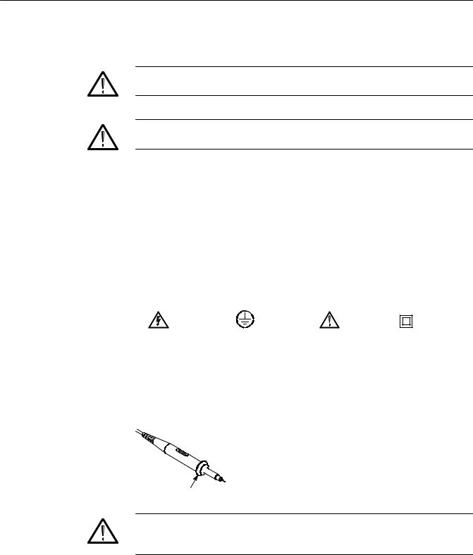
Symbols on the Product. The following symbols may appear on the product:
DANGER |
Protective Ground |
ATTENTION |
Double |
High Voltage |
(Earth) Terminal |
Refer to Manual |
Insulated |
Probe Safety A guard around the probe body provides a finger barrier for protection from electric shock.
Finger guard
WARNING. To avoid electric shock when using the probe, keep fingers behind the guard on the probe body, and do not touch metallic portions of the probe head while it is connected to a voltage source.
Connect the probe to the oscilloscope and connect the ground terminal to ground before you take any measurements.
viii |
TDS1000 and TDS2000 Series Digital Storage Oscilloscopes Service Manual |

Service Safety Summary
Only qualified personnel should perform service procedures. Read this Service Safety Summary and the General Safety Summary before performing any service procedures.
Do Not Service Alone. Do not perform internal service or adjustments of this product unless another person capable of rendering first aid and resuscitation is present.
Disconnect Power. To avoid electric shock, disconnect the main power by means of the power cord or, if provided, the power switch.
Use Care When Servicing With Power On. Dangerous voltages or currents may exist in this product. Disconnect power, remove battery (if applicable), and disconnect test leads before removing protective panels, soldering, or replacing components.
To avoid electric shock, do not touch exposed connections.
TDS1000 and TDS2000 Series Digital Storage Oscilloscopes Service Manual |
ix |

Service Safety Summary
x |
TDS1000 and TDS2000 Series Digital Storage Oscilloscopes Service Manual |
Environmental Considerations
Product End-of-Life
Handling
Restriction of Hazardous
Substances
This section provides information about the environmental impact of the product.
Observe the following guidelines when recycling an instrument or component:
Equipment Recycling. Production of this equipment required the extraction and use of natural resources. The equipment may contain substances that could be harmful to the environment or human health if improperly handled at the product’s end of life. In order to avoid release of such substances into the environment and to reduce the use of natural resources, we encourage you to recycle this product in an appropriate system that will ensure that most of the materials are reused or recycled appropriately.
The symbol shown to the left indicates that this product complies with the European Union’s requirements according to Directive 2002/96/EC on waste electrical and electronic equipment (WEEE). For information about recycling options, check the Support/Service section of the Tektronix Web site (www.tektronix.com).
Mercury Notification. This product uses an LCD backlight lamp that contains mercury. Disposal may be regulated due to environmental considerations. Please contact your local authorities or, within the United States, the Electronics Industries Alliance (www.eiae.org) for disposal or recycling information.
This product has been classified as Monitoring and Control equipment, and is outside the scope of the 2002/95/EC RoHS Directive. This product is known to contain lead, cadmium, mercury, and hexavalent chromium.
TDS1000 and TDS2000 Series Digital Storage Oscilloscopes Service Manual |
xi |

Environmental Considerations
xii |
TDS1000 and TDS2000 Series Digital Storage Oscilloscopes Service Manual |

Preface
The service manual for the TDS1000and TDS2000-Series Digital Storage Oscilloscopes provides instructions to verify the performance of, calibrate, troubleshoot, and repair the oscilloscopes to the module level.
Unless noted otherwise, the term “oscilloscope” refers to all of the models in the
TDS1000 and TDS2000 series.
Related Manuals
These manuals contain additional documentation for the oscilloscopes:
|
|
Extension module |
|
|
User manual |
instructions part |
Programmer manual |
Language |
part number |
number |
part number |
|
|
|
|
English |
071-1064-XX |
071-0409-XX |
071-1075-XX |
|
|
|
|
French |
071-1065-XX* |
071-0483-XX |
|
|
|
|
|
German |
071-1067-XX* |
071-0485-XX |
|
|
|
|
|
Italian |
071-1066-XX* |
071-0484-XX |
|
|
|
|
|
Spanish |
071-1068-XX* |
071-0482-XX |
|
|
|
|
|
Portuguese |
071-1070-XX* |
071-0486-XX |
|
|
|
|
|
Japanese |
071-1069-XX* |
071-0488-XX |
|
|
|
|
|
Korean |
071-1073-XX* |
071-0491-XX |
|
|
|
|
|
Simplified Chinese |
071-1071-XX* |
071-0489-XX |
|
|
|
|
|
Traditional Chinese |
071-1072-XX* |
071-0490-XX |
|
|
|
|
|
Russian |
071-1074-XX* |
071-0487-XX |
|
|
|
|
|
*These manuals contain a language overlay for the front-panel controls.
TDS1000 and TDS2000 Series Digital Storage Oscilloscopes Service Manual |
xiii |

Preface
xiv |
TDS1000 and TDS2000 Series Digital Storage Oscilloscopes Service Manual |

Specifications
Specifications
These specifications apply to all TDS1000and TDS2000-series oscilloscopes. To verify that an oscilloscope meets specifications, it must first meet the following conditions:
H The oscilloscope must have been operating continuously for twenty minutes within the specified operating temperature.
H You must perform the Do Self Cal operation, accessible through the Utility menu, if the operating temperature changes by more than 5 °C.
|
H The oscilloscope must be within the factory calibration interval of one year. |
|
|
Specifications begin in Table 1-1. All specifications are guaranteed unless noted |
|
|
“typical.” Specifications that are marked with the n symbol are checked in the |
|
|
chapter Performance Verification. |
|
Table 1- 1: Oscilloscope specifications |
|
|
|
|
|
Acquisition |
|
|
|
|
|
Acquisition Modes |
Sample, Peak Detect, and Average |
|
|
|
|
Acquisition Rate, |
Up to 180 waveforms per second, per channel (Sample acquisition mode, no measurements) |
|
typical |
|
|
|
|
|
Single Sequence |
Acquisition Mode |
Acquisition Stops After |
|
|
|
|
Sample, Peak Detect |
Single acquisition, all channels simultaneously |
|
|
|
|
Average |
N acquisitions, all channels simultaneously. N is selectable from 4, |
|
|
16, 64, and 128 |
|
|
|
Inputs |
|
|
|
|
|
Input Coupling |
DC, AC, or GND |
|
|
|
|
Input Impedance, DC |
1 MΩ ±2% in parallel with 20 pF ±3 pF |
|
Coupled |
|
|
|
|
|
P2200 Probe |
1X, 10X |
|
Attenuation |
|
|
|
|
|
Supported Probe |
1X, 10X, 100X, 1000X |
|
Attenuation Factors |
|
|
|
|
|
TDS1000 and TDS2000 Series Digital Storage Oscilloscopes Service Manual |
1- 1 |

Specifications
Table 1- 1: Oscilloscope specifications (Cont.)
Inputs
Maximum Voltage |
Overvoltage Category* |
Maximum Voltage |
|
||
Between Signal and |
|
|
|
|
|
CAT I and CAT II |
|
300 VRMS |
|
||
Common at input BNC |
|
|
|||
|
|
|
|
|
|
CAT III |
|
150 VRMS |
|
||
|
|
|
|||
|
Derate at 20 dB/decade above 100 kHz to 13 V peak AC at 3 MHz and above. |
|
|||
|
|
|
|
|
|
|
For non-sinusoidal waveforms, peak value must be less than 450 V. Excursion above 300 V should be less |
||||
|
than 100 ms duration. |
|
|
|
|
|
RMS signal level including any DC component removed through AC coupling must be limited to 300 V. |
||||
|
|
|
|
|
|
|
If these values are exceeded, damage to the oscilloscope may result. |
|
|||
|
|
|
|
|
|
Channel-to-Channel |
TDS1001 |
TDS1002, TDS2002, TDS2004 |
TDS1012, TDS2012, TDS2014, TDS2022, TDS2024 |
||
Common Mode |
|
|
|
|
|
100:1 at 60 Hz |
100:1 at 60 Hz |
|
100:1 at 60 Hz |
|
|
Rejection, typical |
|
|
|||
20:1 at 20 MHz |
20:1 at 30 MHz |
|
10:1 at 50 MHz |
|
|
|
|
|
|||
|
|
|
|
|
|
|
Measured on MATH Ch1 -- Ch2 waveform, with test signal applied between signal and common of both |
||||
|
channels, and with the same VOLTS/DIV and coupling settings on each channel |
|
|||
|
Measured on MATH Ch3 -- Ch4 waveform for 4-channel models |
|
|||
|
|
|
|
||
Channel-to-Channel |
TDS1001 |
TDS1002, TDS2002, TDS2004 |
TDS1012, TDS2012, TDS2014 |
TDS2022, TDS2024 |
|
Crosstalk |
|
|
|
|
|
≥ 100:1 at 20 MHz |
≥ 100:1 at 30 MHz |
|
≥ 100:1 at 50 MHz |
≥ 100:1 at 100 MHz |
|
|
|
||||
|
|
|
|
|
|
|
Measured on one channel, with test signal applied between signal and common of the other channel, and |
||||
|
with the same VOLTS/DIV and coupling settings on each channel |
|
|||
|
|
|
|
|
|
Vertical |
|
|
|
|
|
|
|
|
|||
Digitizers |
8-bit resolution (except when set to 2 mV/div), each channel sampled simultaneously |
|
|||
|
|
|
|
|
|
VOLTS/DIV Range |
2 mV/div to 5 V/div at input BNC |
|
|
|
|
|
|
|
|
|
|
Position Range |
2 mV/div to 200 mV/div, ±2 V |
|
|
|
|
|
> 200 mV/div to 5 V/div, ±50 V |
|
|
|
|
|
|
|
|
|
|
*Refer to the Overvoltage Category description on page 1-10.
1- 2 |
TDS1000 and TDS2000 Series Digital Storage Oscilloscopes Service Manual |

Specifications
Table 1- 1: Oscilloscope specifications
Vertical
n Analog Bandwidth TDS1001 |
TDS1002, TDS2002, TDS2004 |
TDS1012, TDS2012, TDS2014 |
TDS2022, TDS2024 |
||
in Sample and Average |
40 MHz{* |
60 MHz{* |
100 MHz{* |
200 MHz{* |
|
modes at BNC or with |
|||||
|
|
|
0 °C to +40 °C (32 °F |
||
P2200 probe, |
|
|
|
||
|
|
|
to 104 °F) |
||
DC Coupled |
|
|
|
||
|
|
|
|
||
|
|
|
|
160 MHz{* |
|
|
|
|
|
0 °C to +50 °C (32 °F |
|
|
|
|
|
to 122 °F) |
|
|
|
|
|
|
|
20 MHz* (when vertical scale is set to < 5 mV)
Analog Bandwidth in |
|
TDS1001 |
TDS1002, TDS2002, TDS2004 |
|
TDS1012, TDS2012, TDS2014, TDS2022, TDS2024 |
|
Peak Detect mode |
|
|
|
|
|
|
|
30 MHz{* |
50 MHz{* |
|
75 MHz{* |
|
|
(50 s/div to 5 s/div**), |
|
|
|
|||
|
20 MHz* (when vertical scale is set to < 5 mV) |
|
|
|||
typical |
|
|
|
|||
Selectable Analog Band- |
|
20 MHz* |
|
|
|
|
width Limit, typical |
|
|
|
|
|
|
|
|
|
|
|
||
Lower Frequency |
|
≤ 10 Hz at BNC |
|
|
||
Limit, AC Coupled |
|
≤ 1 Hz when using a 10X passive probe |
|
|
||
|
|
|
|
|
|
|
Rise Time at BNC, |
|
TDS1001 |
TDS1002, TDS2002, TDS2004 |
|
TDS1012, TDS2012, TDS2014 |
TDS2022, TDS2024 |
typical |
|
|
|
|
|
|
|
< 8.4ns |
< 5.8 ns |
|
< 3.5 ns |
< 2.1 ns |
|
|
|
|
||||
|
|
|
|
|
|
|
Peak Detect Response** Captures 50% or greater amplitude of pulses ≥12 ns wide typical (50 s/div to 5 s/div) in the center 8 vertical divisions
nDC Gain Accuracy ±3% for Sample or Average acquisition mode, 5 V/div to 10 mV/div
|
±4% for Sample or Average acquisition mode, 5 mV/div and 2 mV/div |
||
|
|
|
|
n DC Measurement |
Measurement Type |
Accuracy |
|
Accuracy, Average |
|
|
|
Average of ≥ 16 waveforms with vertical |
±(3% × reading + 0.1 div + 1 mV) when 10 mV/div or greater |
||
Acquisition Mode |
|||
position at zero |
is selected |
||
|
|||
|
|
|
|
|
Average of ≥ 16 waveforms with vertical |
±[3% × (reading + vertical position) + 1% of vertical position |
|
|
position not at zero |
+ 0.2 div] |
|
|
|
Add 2 mV for settings from 2 mV/div to 200 mV/div |
|
|
|
Add 50 mV for settings from > 200 mV/div to 5 V/div |
|
|
|
|
|
Volts Measurement |
Delta volts between any two averages of ≥ |
±(3% × reading + 0.05 div) |
|
Repeatability, Average |
16 waveforms acquired under same setup |
|
|
Acquisition Mode |
and ambient conditions |
|
|
|
|
|
|
{ When vertical scale is set to ≥ 5 mV.
*Bandwidth reduced to 6 MHz with a 1X probe.
**The oscilloscope reverts to Sample mode when the SEC/DIV (horizontal scale) is set from 2.5 s/div to 5 ns/div on 1 GS/s models, or from 2.5 s/div to 2.5 ns/div on 2 GS/s models. The Sample mode can still capture 10 ns glitches.
TDS1000 and TDS2000 Series Digital Storage Oscilloscopes Service Manual |
1- 3 |

Specifications
Table 1- 1: Oscilloscope specifications (Cont.)
Horizontal
Sample Rate Range |
TDS2022, TDS2024 |
TDS1001, TDS1002, TDS2004, TDS1012, TDS2002, |
|
|
|
TDS2012, TDS2014 |
|
|
|
|
|
|
5 S/s to 2 GS/s |
5 S/s to 1 GS/s |
|
|
|
|
|
Waveform Interpolation |
(sin x)/x |
|
|
|
|
|
|
Record Length |
2500 samples for each channel |
|
|
|
|
|
|
SEC/DIV Range |
TDS2022, TDS2024 |
TDS1001, TDS1002, TDS2004, TDS1012, TDS2002, |
|
|
|
TDS2012, TDS2014 |
|
|
|
|
|
|
2.5 ns/div to 50 s/div, in a 1, 2.5, 5 sequence |
5 ns/div to 50 s/div, in a 1, 2.5, 5 sequence |
|
|
±50 ppm over any ≥1 ms time interval |
|
|
n Sample Rate and |
|
||
Delay Time Accuracy |
|
|
|
|
|
|
|
Delta Time Measurement |
Conditions |
Accuracy |
|
Accuracy (Full Band- |
|
|
|
Single-shot, Sample mode |
±(1 sample interval + 50 ppm × reading + 0.6 ns) |
||
width) |
|||
|
|
||
> 16 averages |
±(1 sample interval + 50 ppm × reading + 0.4 ns) |
||
|
|||
|
Sample interval = s/div ÷ 250 |
|
|
|
|
|
|
Position Range |
5 ns/div to 10 ns/div |
(--4 div × s/div) to 20 ms |
|
|
|
|
|
|
25 ns/div to 100 s/div |
(--4 div × s/div) to 50 ms |
|
|
|
|
|
|
250 s/div to 50 s/div |
(--4 div × s/div) to 50 s |
|
|
TDS2022, TDS2024 |
|
|
|
|
|
|
|
2.5 ns/div |
(--4 div × s/div) to 20 ms |
|
|
|
|
1- 4 |
TDS1000 and TDS2000 Series Digital Storage Oscilloscopes Service Manual |

Specifications
Table 1- 1: Oscilloscope specifications
Trigger |
|
|
|
|
|
|
|
|
|
n Trigger Sensitiv- |
Coupling |
Sensitivity |
TDS1001, TDS1002, |
TDS2022, TDS2024 |
ity, Edge Trigger Type |
|
|
TDS1012, TDS2002, |
|
|
|
|
TDS2004, TDS2012, TDS2014 |
|
|
|
|
|
|
|
DC |
EXT |
200 mV from DC to 100 MHz* |
200 mV from DC to 100 MHz* |
|
|
|
|
350 mV from 100 MHz to 200 MHz* |
|
|
|
|
|
|
|
EXT/5 |
1 V from DC to 100 MHz* |
1 V from DC to 100 MHz* |
|
|
|
|
1.75 V from 100 MHz to 200 MHz* |
|
|
|
|
|
|
|
CH1, CH2, |
1 div from DC to 10 MHz*, 1.5 div from 10 MHz to Full |
|
|
|
CH3, CH4 |
|
|
|
|
|
|
|
Trigger Sensitivity, |
Coupling |
Sensitivity |
|
|
Edge Trigger Type |
|
|
|
|
AC |
Same as DC at 50 Hz and above |
|
||
|
|
|||
|
|
|
||
|
NOISE REJ |
Reduces the DC-coupled trigger sensitivity by 2 times for > 10 mv/div to 5 V/div |
||
|
|
|
||
|
HF REJ |
Same as the DC-coupled limit from DC to 7 kHz, attenuates signals above 80 kHz |
||
|
|
|
||
|
LF REJ |
Same as the DC-coupled limits for frequencies above 300 kHz, attenuates signals |
||
|
|
below 300 kHz |
|
|
|
|
|
|
|
Trigger Level Range |
Source |
Range |
|
|
|
|
|
|
|
|
CH1, CH2, CH3, and |
±8 divisions from center of screen |
|
|
|
CH4 |
|
|
|
|
|
|
|
|
|
EXT |
±1.6 V |
|
|
|
|
|
|
|
|
EXT/5 |
±8 V |
|
|
Trigger Level Accura- |
Accuracies are for signals having rise and fall times ≥ 20 ns |
|
||
cy, typical |
|
|
|
|
Source |
Accuracy |
|
|
|
|
|
|
||
|
|
|
||
|
Internal |
±0.2 div × volts/div within ±4 divisions from center screen |
||
|
|
|
|
|
|
EXT |
±(6% of setting + 40 mV) |
|
|
|
|
|
|
|
|
EXT/5 |
±(6% of setting + 200 mV) |
|
|
SET LEVEL TO 50%, |
Operates with input signals ≥ 50 Hz |
|
|
|
typical |
|
|
|
|
|
|
|
||
Default Settings, |
Coupling is AC and Auto except for a single sequence acquisition |
|
||
Video Trigger |
|
|
|
|
|
|
|
|
|
* Bandwidth reduced to 6 MHz with a 1X probe.
TDS1000 and TDS2000 Series Digital Storage Oscilloscopes Service Manual |
1- 5 |

Specifications
Table 1- 1: Oscilloscope specifications (Cont.)
Trigger
Sensitivity, Video Trig- |
Composite video signal |
|
|
ger Type, typical |
|
|
|
Source |
Range |
||
|
|||
|
|
|
|
|
Internal |
Pk-pk amplitude of 2 divisions |
|
|
|
|
|
|
EXT |
400 mV |
|
|
|
|
|
|
EXT/5 |
2 V |
|
|
|
|
|
Signal Formats and |
Supports NTSC, PAL, and SECAM broadcast systems for any field or any line |
||
Field Rates, Video |
|
|
|
Trigger Type |
|
|
|
|
|
|
|
Holdoff Range |
500 ns to 10 s |
|
|
|
|
|
|
Pulse Width Trigger |
|
|
|
|
|
||
Pulse Width |
Trigger when < (Less than), > (Greater than), = (Equal), or ≠ (Not Equal); |
||
Trigger modes |
Positive pulse or Negative pulse |
||
|
|
||
Pulse Width |
Equal: The oscilloscope triggers when the trailing edge of the pulse crosses the trigger level. |
||
Trigger Point |
Not Equal: If the pulse is narrower than the specified width, the trigger point is the trailing edge. Otherwise, the |
||
|
|||
|
oscilloscope triggers when a pulse continues longer than the time specified as the Pulse Width. |
||
|
Less than: The trigger point is the trailing edge. |
||
|
Greater than (also called time-out trigger): The oscilloscope triggers when a pulse continues longer than the |
||
|
time specified as the Pulse Width. |
||
|
|
||
Pulse Width Range |
Selectable from 33 ns to 10 s |
||
|
|
||
Pulse Width |
16.5 ns or 1 part per thousand, whichever is larger |
||
Resolution |
|
|
|
|
|
||
Equal Guardband |
t > 330 ns: ±5% ≤ guardband < ±(5.1% + 16.5 ns) |
||
|
t ≤ 330 ns: guardband = ±16.5 ns |
||
|
|
||
Not Equal Guardband |
t > 330 ns: ±5% ≤ guardband < ±(5.1% + 16.5 ns) |
||
|
165 ns < t ≤ 330 ns: guardband = --16.5 ns/+33 ns |
||
|
t ≤ 165 ns: guardband = ±16.5 ns |
||
|
|
|
|
Trigger Frequency Counter |
|
||
|
|
|
|
Readout Resolution |
6 digits |
|
|
|
|
||
Accuracy (typical) |
±51 ppm including all frequency reference errors and ±1 count errors |
||
|
|
||
Frequency Range |
AC coupled, 10 Hz minimum to rated bandwidth |
||
|
|
|
|
1- 6 |
TDS1000 and TDS2000 Series Digital Storage Oscilloscopes Service Manual |

Specifications
Table 1- 1: Oscilloscope specifications (Cont.)
Trigger Frequency Counter
Signal Source |
Pulse Width or Edge Trigger modes: all available trigger sources |
|
The Frequency Counter measures trigger source at all times, including when the oscilloscope acquisition is |
|
halted due to changes in the run status, or acquisition of a single shot event has completed. |
|
Pulse Width Trigger mode: The oscilloscope counts pulses of significant magnitude inside the 250 ms |
|
measurement window that qualify as triggerable events, such as narrow pulses in a PWM pulse train if set to < |
|
mode and the width is set to a relatively small time. |
|
Edge Trigger mode: The oscilloscope counts all edges of sufficient magnitude and correct polarity. |
|
Video Trigger mode: The Frequency Counter does not operate. |
|
|
Measurements |
|
|
|
Cursors |
Voltage difference between cursors ( V) |
|
Time difference between cursors ( T) |
|
Reciprocal of T in Hertz (1/ T) |
|
|
Automatic Measure- |
Frequency, Period, Mean, Pk-Pk, Cycle RMS, Min, Max, Rise Time, Fall Time, Pos Width, Neg Width |
ments |
|
|
|
Table 1- 2: Oscilloscope general specifications
Display |
|
|
|
|
|
Display Type |
|
145 mm (5.7 in) diagonal liquid crystal |
|
|
|
Display Resolution |
|
320 horizontal by 240 vertical pixels |
|
|
|
Display Contrast |
|
Adjustable, temperature compensated |
|
|
65 cd/m2 |
Backlight Intensity, typical |
|
|
Probe Compensator Output |
|
|
|
|
|
Output Voltage, typical |
|
5 V into ≥ 1 MΩ load |
|
|
|
Frequency, typical |
|
1 kHz |
|
|
|
Power Source |
|
|
|
|
|
Source Voltage |
|
100 -- 120 VACRMS ( 10%) from 45 Hz through 440 Hz, CAT II |
|
|
120 -- 240 VACRMS ( 10%) from 45 Hz through 66 Hz, CAT II |
Power Consumption |
|
Less than 30 W |
|
|
|
Fuse |
|
1 A, T rating, 250 V |
|
|
|
TDS1000 and TDS2000 Series Digital Storage Oscilloscopes Service Manual |
1- 7 |

Specifications
Table 1- 2: Oscilloscope general specifications (Cont.)
Environmental
Temperature |
Operating |
0 °C to +50 °C (32 °F to 122 °F) |
|
|
|
|
Nonoperating |
--40 °C to +71 °C (--40 °F to 159.8 °F) |
|
|
|
Cooling Method |
Convection |
|
|
|
|
Humidity |
+40 °C or below |
≤ 90% relative humidity |
|
(+104 °F or below) |
|
|
|
|
|
+41° C to +50° C |
≤ 60% relative humidity |
|
(106 °F to 122 °F) |
|
|
|
|
Altitude |
Operating and Nonoperating |
3,000 m (10,000 ft) |
|
|
|
Random Vibration |
Operating |
0.31 gRMS from 5 Hz to 500 Hz, 10 minutes on each axis |
|
|
|
|
Nonoperating |
2.46 gRMS from 5 Hz to 500 Hz, 10 minutes on each axis |
|
|
|
Mechanical Shock |
Operating |
50 g, 11 ms, half sine |
|
|
|
Mechanical |
|
|
|
|
|
Size |
Height |
151.4 mm (5.96 in) |
|
|
|
|
Width |
323.8 mm (12.75 in) |
|
|
|
|
Depth |
124.5 mm (4.90 in) |
|
|
|
Weight (approximate) |
When packaged for domestic shipment |
3.6 kg (8.0 lbs) |
|
|
|
Certifications and Compliances
EN 61326. EMC requirements for Class A electrical equipment for measurement, control, and laboratory use. Annex D.
HIEC 61000-4-2. Electrostatic discharge immunity
HIEC 61000-4-3. RF electromagnetic field immunity
HIEC 61000-4-4. Electrical fast transient / burst immunity
HIEC 61000-4-5. Power line surge immunity
HIEC 61000-4-6. Conducted RF Immunity
HIEC 61000-4-11. Voltage dips and interruptions immunity
EN 61000- 3- 2. AC power line harmonic emissions1
EN 61000- 3- 3. Voltage changes, fluctuations, and flicker
1Emissions which exceed the levels required by this standard may occur when this equipment is connected to a test object.
1- 8 |
TDS1000 and TDS2000 Series Digital Storage Oscilloscopes Service Manual |

Specifications
Australia / New Zealand |
Complies with EMC provision of Radiocommunications Act per these stan- |
Declaration of Conformity |
dard(s): |
- EMC |
H AS/NZS 2064.1/2. Industrial, Scientific, and Medical Equipment: 1992 |
|
|
EMC Compliance |
Meets the intent of Directive 89/336/EEC for Electromagnetic Compatibility |
|
when it is used with the product(s) stated in the specifications table. Refer to the |
|
EMC specification published for the stated products. May not meet the intent of |
|
the directive if used with other products. |
FCC Compliance |
Emissions comply with FCC 47 CFR, Part 15, Subpart B for Class A equipment. |
Russian Federation |
This product was certified by the GOST ministry of Russia to be in compliance |
|
with all applicable EMC regulations. |
Peoples Republic of China |
This product has received the Chinese Metrology Certification. (CMC). |
EC Declaration of |
Compliance was demonstrated to the following specification as listed in the |
Conformity - Low Voltage |
Official Journal of the European Communities: |
|
Low Voltage Directive 73/23/EEC, amended by 93/68/EEC. |
|
H EN 61010-1:2001. Safety requirements for electrical equipment for |
|
measurement control and laboratory use. |
|
H EN 61010-2-031:2002. Particular requirements for handheld probe assem- |
|
blies for electrical measurement and test equipment. |
U.S. Nationally |
H UL 61010B-1:2004, 2nd Edition. Standard for electrical measuring and test |
Recognized Testing |
equipment. |
Laboratory Listing |
H UL 61010B-2-031:2003. Particular requirements for handheld probe |
|
|
|
assemblies for electrical measurement and test equipment. |
Canadian Certification |
H CAN/CSA C22.2 No. 1010.1:1997. Particular requirements for electrical |
|
equipment for measurement, control, and laboratory use. Part 1. |
|
H CAN/CSA C22.2 No. 61010-2-031:1994. Particular requirements for |
|
handheld probe assemblies for electrical measurement and test equipment. |
Additional Compliance |
H IEC 61010-1:2001. Safety requirements for electrical equipment for |
|
measurement, control, and laboratory use. |
TDS1000 and TDS2000 Series Digital Storage Oscilloscopes Service Manual |
1- 9 |

Specifications
HIEC 61010-031:2002. Particular requirements for handheld probe assemblies for electrical measurement and test equipment.
Equipment Type Test and measuring equipment.
Pollution Degree A measure of the contaminates that could occur in the environment around and Descriptions within a product. Typically the internal environment inside a product is
considered to be the same as the external. Products should be used only in the environment for which they are rated.
HPollution Degree 1. No pollution or only dry, nonconductive pollution occurs. Products in this category are generally encapsulated, hermetically sealed, or located in clean rooms.
HPollution Degree 2. Normally only dry, nonconductive pollution occurs. Occasionally a temporary conductivity that is caused by condensation must be expected. This location is a typical office/home environment. Temporary condensation occurs only when the product is out of service.
HPollution Degree 3. Conductive pollution, or dry, nonconductive pollution that becomes conductive due to condensation. These are sheltered locations where neither temperature nor humidity is controlled. The area is protected from direct sunshine, rain, or direct wind.
HPollution Degree 4. Pollution that generates persistent conductivity through conductive dust, rain, or snow. Typical outdoor locations.
Pollution Degree Pollution Degree 2 (as defined in IEC 61010-1). Note: Rated for indoor use only.
Installation (Overvoltage) Terminals on this product may have different installation (overvoltage) category Category Descriptions designations. The installation categories are:
HMeasurement Category IV. For measurements performed at the source of low-voltage installation.
HMeasurement Category III. For measurements performed in the building installation.
HMeasurement Category II. For measurements performed on circuits directly connected to the low-voltage installation.
HMeasurement Category I. For measurements performed on circuits not directly connected to MAINS.
Overvoltage Category Overvoltage Category II (as defined in IEC 61010-1)
1- 10 |
TDS1000 and TDS2000 Series Digital Storage Oscilloscopes Service Manual |
Loading...