


 Loading...
Operator's Manual
1780R-Series
Video Measurement Set
070-6890-08
This document supports firmware version 1.10 to 1.16.
Copyright Tektronix, Inc. All rights reserved.
Tektronix products are covered by U.S. and foreign patents, issued and pending. Information in this publication supercedes that in all previously published material. Specifications and price change privileges reserved.
Tektronix, Inc., P.O. Box 1000, Wilsonville, OR 97070±1000
TEKTRONIX and TEK are registered trademarks of Tektronix, Inc.
WARRANTY
Tektronix warrants that the products that it manufactures and sells will be free from defects in materials and workmanship for a period of three (3) years from the date of shipment. If a product proves defective during this warranty period, Tektronix, at its option, either will repair the defective product without charge for parts and labor, or will provide a replacement in exchange for the defective product.
In order to obtain service under this warranty, Customer must notify Tektronix of the defect before the expiration of the warranty period and make suitable arrangements for the performance of service. Customer shall be responsible for packaging and shipping the defective product to the service center designated by Tektronix, with shipping charges prepaid. Tektronix shall pay for the return of the product to Customer if the shipment is to a location within the country in which the Tektronix service center is located. Customer shall be responsible for paying all shipping charges, duties, taxes, and any other charges for products returned to any other locations.
This warranty shall not apply to any defect, failure or damage caused by improper use or improper or inadequate maintenance and care. Tektronix shall not be obligated to furnish service under this warranty a) to repair damage resulting from attempts by personnel other than Tektronix representatives to install, repair or service the product; b) to repair damage resulting from improper use or connection to incompatible equipment; c) to repair any damage or malfunction caused by the use of non-Tektronix supplies; or d) to service a product that has been modified or integrated with other products when the effect of such modification or integration increases the time or difficulty of servicing the product.
THIS WARRANTY IS GIVEN BY TEKTRONIX IN LIEU OF ANY OTHER WARRANTIES, EXPRESS OR IMPLIED. TEKTRONIX AND ITS VENDORS DISCLAIM ANY IMPLIED WARRANTIES OF MERCHANTABILITY OR FITNESS FOR A PARTICULAR PURPOSE. TEKTRONIX' RESPONSIBILITY TO REPAIR OR REPLACE DEFECTIVE PRODUCTS IS THE SOLE AND EXCLUSIVE REMEDY PROVIDED TO THE CUSTOMER FOR BREACH OF THIS WARRANTY. TEKTRONIX AND ITS VENDORS WILL NOT BE LIABLE FOR ANY INDIRECT, SPECIAL, INCIDENTAL, OR CONSEQUENTIAL DAMAGES IRRESPECTIVE OF WHETHER TEKTRONIX OR THE VENDOR HAS ADVANCE NOTICE OF THE POSSIBILITY OF SUCH DAMAGES.
Contacting Tektronix
Product |
For questions about using Tektronix measurement |
Support |
products, call toll free in North America: |
|
1-800-TEK-WIDE (1-800-835-9433 ext. 2400) |
|
6:00 a.m. ± 5:00 p.m. Pacific time |
|
Or contact us by e-mail: |
|
tm_app_supp@tek.com |
|
For product support outside of North America, |
|
contact your local Tektronix distributor or sales |
|
office. |
Service |
Tektronix offers extended warranty and calibration |
Support |
programs as options on many products. Contact |
|
your local Tektronix distributor or sales office. |
|
For a listing of worldwide service centers, visit our |
|
web site. |
For other |
In North America: |
information |
1-800-TEK-WIDE (1-800-835-9433) |
|
An operator will direct your call. |
To write us |
Tektronix, Inc. |
|
P.O. Box 1000 |
|
Wilsonville, OR 97070-1000 |
|
USA |
Website |
Tektronix.com |

Table of Contents
General Safety Summary . . . . . . . . . . . . . . . . . . . . . . . . . . . . |
xi |
Getting Started
Documentation Overview . . . . . . . . . . . . . . . . . . . . . . . . . . . . . |
1±1 |
Operator's Manual . . . . . . . . . . . . . . . . . . . . . . . . . . . . . . . . |
1±1 |
Service Manual . . . . . . . . . . . . . . . . . . . . . . . . . . . . . . . . . . |
1±1 |
Documentation Conventions . . . . . . . . . . . . . . . . . . . . . . . . . . . |
1±2 |
Who Should Use This Operator's Manual . . . . . . . . . . . . . . . . . |
1±2 |
1780R-Series Product Overview . . . . . . . . . . . . . . . . . . . . . . . . |
1±2 |
New Capabilities . . . . . . . . . . . . . . . . . . . . . . . . . . . . . . . . . |
1±3 |
Touch Screen . . . . . . . . . . . . . . . . . . . . . . . . . . . . . . . . . . . . |
1±3 |
1780R-Series Package . . . . . . . . . . . . . . . . . . . . . . . . . . . . . . . . |
1±4 |
Mechanical Installation . . . . . . . . . . . . . . . . . . . . . . . . . . . . . . . |
1±4 |
Rack-Mounting . . . . . . . . . . . . . . . . . . . . . . . . . . . . . . . . . . . . . |
1±4 |
Options . . . . . . . . . . . . . . . . . . . . . . . . . . . . . . . . . . . . . . . . . . . . |
1±9 |
Standard Accessories . . . . . . . . . . . . . . . . . . . . . . . . . . . . . . . . . |
1±9 |
Optional Accessories . . . . . . . . . . . . . . . . . . . . . . . . . . . . . . . . . |
1±10 |
Connectors, Controls, Indicators
Switches . . . . . . . . . . . . . . . . . . . . . . . . . . . . . . . . . . . . . . . . |
2±1 |
Companion Switches . . . . . . . . . . . . . . . . . . . . . . . . . . . . . . |
2±1 |
Controls . . . . . . . . . . . . . . . . . . . . . . . . . . . . . . . . . . . . . . . . |
2±1 |
LEDs . . . . . . . . . . . . . . . . . . . . . . . . . . . . . . . . . . . . . . . . . . |
2±1 |
Audio Feedback (Beep) . . . . . . . . . . . . . . . . . . . . . . . . . . . . . . . |
2±2 |
A Beep Sounds When: . . . . . . . . . . . . . . . . . . . . . . . . . . . . . |
2±2 |
Disable the Beep . . . . . . . . . . . . . . . . . . . . . . . . . . . . . . . . . |
2±2 |
A ªClickº Occurs When: . . . . . . . . . . . . . . . . . . . . . . . . . . . |
2±2 |
Touch Screen . . . . . . . . . . . . . . . . . . . . . . . . . . . . . . . . . . . . . . . |
2±2 |
Front-Panel Controls . . . . . . . . . . . . . . . . . . . . . . . . . . . . . . . . . |
2±3 |
1780R-Series Operator's Manual |
i |

Table of Contents
Power . . . . . . . . . . . . . . . . . . . . . . . . . . . . . . . . . . . . . . . . . . |
2±3 |
CRT Controls . . . . . . . . . . . . . . . . . . . . . . . . . . . . . . . . . . . . |
2±3 |
Precision Measurement (Large Knob) . . . . . . . . . . . . . . . . . |
2±5 |
Menu Access Switches . . . . . . . . . . . . . . . . . . . . . . . . . . . . |
2±7 |
Probe . . . . . . . . . . . . . . . . . . . . . . . . . . . . . . . . . . . . . . . . . . |
2±8 |
Display Mode . . . . . . . . . . . . . . . . . . . . . . . . . . . . . . . . . . . . |
2±9 |
Ref . . . . . . . . . . . . . . . . . . . . . . . . . . . . . . . . . . . . . . . . . . . . |
2±12 |
Wfm Horizontal . . . . . . . . . . . . . . . . . . . . . . . . . . . . . . . . . . |
2±12 |
Magnifier . . . . . . . . . . . . . . . . . . . . . . . . . . . . . . . . . . . . . . . |
2±12 |
Gain . . . . . . . . . . . . . . . . . . . . . . . . . . . . . . . . . . . . . . . . . . . |
2±13 |
Filter . . . . . . . . . . . . . . . . . . . . . . . . . . . . . . . . . . . . . . . . . . . |
2±14 |
Input . . . . . . . . . . . . . . . . . . . . . . . . . . . . . . . . . . . . . . . . . . . |
2±15 |
Rear Panel Connectors . . . . . . . . . . . . . . . . . . . . . . . . . . . . . . . . |
2±16 |
Operating Instructions
Large Knob And Associated Switches . . . . . . . . . . . . . . . . . . . |
3±1 |
Timing Cursors . . . . . . . . . . . . . . . . . . . . . . . . . . . . . . . . . . |
3±1 |
Voltage Cursors . . . . . . . . . . . . . . . . . . . . . . . . . . . . . . . . . . |
3±2 |
Line Select . . . . . . . . . . . . . . . . . . . . . . . . . . . . . . . . . . . . . . |
3±3 |
Phase Shift . . . . . . . . . . . . . . . . . . . . . . . . . . . . . . . . . . . . . . |
3±5 |
Reference Set . . . . . . . . . . . . . . . . . . . . . . . . . . . . . . . . . . . . |
3±5 |
Knob . . . . . . . . . . . . . . . . . . . . . . . . . . . . . . . . . . . . . . . . . . . |
3±6 |
< > Switches . . . . . . . . . . . . . . . . . . . . . . . . . . . . . . . . . . . . . |
3±6 |
Graticules . . . . . . . . . . . . . . . . . . . . . . . . . . . . . . . . . . . . . . . . . . |
3±6 |
Scale Illumination for Vector and Waveform Graticules . . . |
3±6 |
Using The Vector Graticule . . . . . . . . . . . . . . . . . . . . . . . . . |
3±6 |
Using The Waveform Graticule . . . . . . . . . . . . . . . . . . . . . . |
3±12 |
Remote Operation . . . . . . . . . . . . . . . . . . . . . . . . . . . . . . . . . . . |
3±15 |
REMOTE Connector . . . . . . . . . . . . . . . . . . . . . . . . . . . . . . |
3±15 |
Remote Operation . . . . . . . . . . . . . . . . . . . . . . . . . . . . . . . . |
3±15 |
Serial Communications Interface . . . . . . . . . . . . . . . . . . . . . . . |
3±18 |
Serial Interface Connector . . . . . . . . . . . . . . . . . . . . . . . . . . |
3±18 |
Building a Wiring Converter . . . . . . . . . . . . . . . . . . . . . . . . |
3±18 |
Serial Remote Information . . . . . . . . . . . . . . . . . . . . . . . . . . |
3±19 |
SCH Display . . . . . . . . . . . . . . . . . . . . . . . . . . . . . . . . . . . . . . . |
3±21 |
SCH Phase Measurement Procedure . . . . . . . . . . . . . . . . . . |
3±22 |
ii |
1780R-Series Operator's Manual |

Table of Contents
Parade Operation . . . . . . . . . . . . . . . . . . . . . . . . . . . . . . . . . . . . 3±23
Two Line or Field Parade . . . . . . . . . . . . . . . . . . . . . . . . . . . 3±23
Three Line Display . . . . . . . . . . . . . . . . . . . . . . . . . . . . . . . 3±23
Offset Menu . . . . . . . . . . . . . . . . . . . . . . . . . . . . . . . . . . . . . 3±23
DC Level Measurements . . . . . . . . . . . . . . . . . . . . . . . . . . . 3±24
DC Level Measurement Procedure . . . . . . . . . . . . . . . . . . . 3±25
Overlay Operation . . . . . . . . . . . . . . . . . . . . . . . . . . . . . . . . . . . 3±26
Overlaid Displays . . . . . . . . . . . . . . . . . . . . . . . . . . . . . . . . . 3±26
Offset Menu . . . . . . . . . . . . . . . . . . . . . . . . . . . . . . . . . . . . . 3±26
WFM + CAL . . . . . . . . . . . . . . . . . . . . . . . . . . . . . . . . . . . . . . . 3±27
Enter WFM+CAL Mode . . . . . . . . . . . . . . . . . . . . . . . . . . . 3±27
General WFM+CAL Information . . . . . . . . . . . . . . . . . . . . 3±27
Menu Information . . . . . . . . . . . . . . . . . . . . . . . . . . . . . . . . . . . 3±31
Menu Documentation Overview . . . . . . . . . . . . . . . . . . . . . 3±31
Menu Access . . . . . . . . . . . . . . . . . . . . . . . . . . . . . . . . . . . . 3±32
Touch Screen . . . . . . . . . . . . . . . . . . . . . . . . . . . . . . . . . . . . 3±32
Password Menu . . . . . . . . . . . . . . . . . . . . . . . . . . . . . . . . . . . . . 3±34
Enable / Disable the Password . . . . . . . . . . . . . . . . . . . . . . . 3±34
Define the Password . . . . . . . . . . . . . . . . . . . . . . . . . . . . . . 3±34
Change the Password . . . . . . . . . . . . . . . . . . . . . . . . . . . . . . 3±35
Use the Password . . . . . . . . . . . . . . . . . . . . . . . . . . . . . . . . . 3±35
Incorrect Password . . . . . . . . . . . . . . . . . . . . . . . . . . . . . . . . 3±35
Preset Menu . . . . . . . . . . . . . . . . . . . . . . . . . . . . . . . . . . . . . . . . 3±36
Recall . . . . . . . . . . . . . . . . . . . . . . . . . . . . . . . . . . . . . . . . . . 3±36
Recover . . . . . . . . . . . . . . . . . . . . . . . . . . . . . . . . . . . . . . . . 3±38
Store . . . . . . . . . . . . . . . . . . . . . . . . . . . . . . . . . . . . . . . . . . . 3±39
Name . . . . . . . . . . . . . . . . . . . . . . . . . . . . . . . . . . . . . . . . . . 3±40
Calibrate Menu . . . . . . . . . . . . . . . . . . . . . . . . . . . . . . . . . . . . . 3±42
General Calibration Menu Information . . . . . . . . . . . . . . . . 3±42
Waveform Calibration Information . . . . . . . . . . . . . . . . . . . 3±42
Waveform Calibration Procedure . . . . . . . . . . . . . . . . . . . . . 3±43
Vectorscope Calibration Information . . . . . . . . . . . . . . . . . . 3±46
Vectorscope Calibration Procedure . . . . . . . . . . . . . . . . . . . 3±46
Vectorscope Calibration Procedure . . . . . . . . . . . . . . . . . . . 3±49
Configure Menu . . . . . . . . . . . . . . . . . . . . . . . . . . . . . . . . . . . . . 3±52
Changing Configurations . . . . . . . . . . . . . . . . . . . . . . . . . . . 3±52
1780R-Series Operator's Manual |
iii |

Table of Contents
Measure Menu . . . . . . . . . . . . . . . . . . . . . . . . . . . . . . . . . . . . . . |
3±56 |
Using the Measure Menu . . . . . . . . . . . . . . . . . . . . . . . . . . . |
3±56 |
Beep . . . . . . . . . . . . . . . . . . . . . . . . . . . . . . . . . . . . . . . . . . . |
3±57 |
Store and Recall Modified Setups . . . . . . . . . . . . . . . . . . . . |
3±57 |
Making Measurements . . . . . . . . . . . . . . . . . . . . . . . . . . . . . |
3±58 |
Measurements |
|
Measurement Information . . . . . . . . . . . . . . . . . . . . . . . . . . . . . |
4±1 |
Differential Phase Measurement . . . . . . . . . . . . . . . . . . . . . . . . |
4±2 |
Enter DIFF PHASE Mode . . . . . . . . . . . . . . . . . . . . . . . . . . |
4±2 |
Exit DIFF PHASE Mode . . . . . . . . . . . . . . . . . . . . . . . . . . . |
4±2 |
DIFF PHASE Menu Selections . . . . . . . . . . . . . . . . . . . . . . |
4±2 |
DIFF PHASE Measurement Information . . . . . . . . . . . . . . |
4±5 |
Single-Trace DIFF PHASE Measurement Procedure . . . . . |
4±5 |
Double-Trace DIFF PHASE Measurement Procedure . . . . |
4±6 |
Using Line Select in DIFF PHASE . . . . . . . . . . . . . . . . . . . |
4±6 |
Differential Gain Measurement . . . . . . . . . . . . . . . . . . . . . . . . . |
4±7 |
Enter DIFF GAIN Mode . . . . . . . . . . . . . . . . . . . . . . . . . . . |
4±7 |
Exit DIFF GAIN Mode . . . . . . . . . . . . . . . . . . . . . . . . . . . . |
4±7 |
DIFF GAIN Menu Selections . . . . . . . . . . . . . . . . . . . . . . . |
4±7 |
DIFF GAIN Measurement Information . . . . . . . . . . . . . . . . |
4±10 |
Single-Trace DIFF GAIN Measurement Procedure . . . . . . |
4±10 |
Double-Trace DIFF GAIN Measurement Procedure . . . . . . |
4±11 |
Using Line Select in DIFF GAIN . . . . . . . . . . . . . . . . . . . . |
4±11 |
Simultaneous Diff Phase & Diff Gain Measurements . . . . . . . . |
4±12 |
Enter DP & DG Mode . . . . . . . . . . . . . . . . . . . . . . . . . . . . . |
4±12 |
Exit DP & DG Mode . . . . . . . . . . . . . . . . . . . . . . . . . . . . . . |
4±12 |
DP & DG Menu Selections . . . . . . . . . . . . . . . . . . . . . . . . . |
4±12 |
DP & DG Measurement Information . . . . . . . . . . . . . . . . . . |
4±14 |
DIFF PHASE & DIFF GAIN Measurement Procedure . . . |
4±15 |
Noise Measurement . . . . . . . . . . . . . . . . . . . . . . . . . . . . . . . . . . |
4±16 |
Enter Noise Measurement Mode . . . . . . . . . . . . . . . . . . . . . |
4±16 |
Exit Noise Measurement Mode . . . . . . . . . . . . . . . . . . . . . . |
4±16 |
Noise Measurement Procedure . . . . . . . . . . . . . . . . . . . . . . |
4±16 |
ICPM Measurement . . . . . . . . . . . . . . . . . . . . . . . . . . . . . . . . . . |
4±17 |
Enter ICPM Measurement Mode . . . . . . . . . . . . . . . . . . . . . |
4±17 |
Exit ICPM Measurement Mode . . . . . . . . . . . . . . . . . . . . . . |
4±17 |
ICPM Measurement Information . . . . . . . . . . . . . . . . . . . . . |
4±17 |
ICPM Measurement Procedure . . . . . . . . . . . . . . . . . . . . . . |
4±18 |
iv |
1780R-Series Operator's Manual |
Table of Contents
K Factor Measurement . . . . . . . . . . . . . . . . . . . . . . . . . . . . . . . |
4±20 |
Enter K Factor Mode . . . . . . . . . . . . . . . . . . . . . . . . . . . . . . |
4±20 |
Making K Factor Measurements . . . . . . . . . . . . . . . . . . . . . |
4±20 |
Chroma / Luma Inequalities Measurement . . . . . . . . . . . . . . . . |
4±23 |
Enter Chroma / Luma Mode . . . . . . . . . . . . . . . . . . . . . . . . |
4±23 |
Exit Chroma / Luma Mode . . . . . . . . . . . . . . . . . . . . . . . . . |
4±23 |
Cursors in Chroma / Luma . . . . . . . . . . . . . . . . . . . . . . . . . . |
4±23 |
Making Chroma / Luma Measurements (Using Cursors) . . |
4±23 |
Chroma / Luma Measurements with Lissajous Display . . . |
4±27 |
Short-Time Distortion Measurement . . . . . . . . . . . . . . . . . . . . . |
4±28 |
Enter Short-Time Distortion Mode . . . . . . . . . . . . . . . . . . . |
4±28 |
Exit Short-Time Distortion Measurement Mode . . . . . . . . . |
4±28 |
Short-Time Distortion Measurement Procedure . . . . . . . . . |
4±28 |
R±Y Sweep Measurement . . . . . . . . . . . . . . . . . . . . . . . . . . . . . |
4±31 |
Enter R±Y Sweep Mode . . . . . . . . . . . . . . . . . . . . . . . . . . . |
4±31 |
Exit R±Y Sweep Measurement Mode . . . . . . . . . . . . . . . . . |
4±31 |
R±Y Sweep Mode Information . . . . . . . . . . . . . . . . . . . . . . |
4±32 |
Using R±Y Sweep Mode . . . . . . . . . . . . . . . . . . . . . . . . . . . |
4±32 |
Bowtie Measurement . . . . . . . . . . . . . . . . . . . . . . . . . . . . . . . . . |
4±33 |
Enter Bowtie Measurement Mode . . . . . . . . . . . . . . . . . . . . |
4±33 |
Bowtie Measurement Procedure . . . . . . . . . . . . . . . . . . . . . |
4±33 |
FSC Time Marks Measurement . . . . . . . . . . . . . . . . . . . . . . . . . |
4±36 |
Enter FSC Time Marks Measurement Mode . . . . . . . . . . . . |
4±36 |
Exit FSC Time Marks Measurement Mode . . . . . . . . . . . . . |
4±36 |
Making SCH Phase Measurements . . . . . . . . . . . . . . . . . . . |
4±37 |
Voltage Cursors in FSC Time Marks Mode . . . . . . . . . . . . . |
4±37 |
Verifying Burst Position . . . . . . . . . . . . . . . . . . . . . . . . . . . . |
4±37 |
Other Measurements . . . . . . . . . . . . . . . . . . . . . . . . . . . . . . . . . |
4±38 |
Specifications |
|
Options and Accessories |
|
Options . . . . . . . . . . . . . . . . . . . . . . . . . . . . . . . . . . . . . . . . . . . . |
6±1 |
Accessories . . . . . . . . . . . . . . . . . . . . . . . . . . . . . . . . . . . . . . . . |
6±1 |
Standard Accessories . . . . . . . . . . . . . . . . . . . . . . . . . . . . . . |
6±1 |
Optional Accessories . . . . . . . . . . . . . . . . . . . . . . . . . . . . . . |
6±2 |
Index
1780R-Series Operator's Manual |
v |

Table of Contents
List of Figures
Figure 1±1: Location of the four screws that secure the |
|
instrument to rack-mounting cabinet or portable case . |
1±5 |
Figure 1±2: Dimensions used for rack-mounting the |
|
1780R-Series Video Measurement Set . . . . . . . . . . . . . . . |
1±6 |
Figure 1±3: Dimensions of the adjustable rear |
|
rack-mounting bracket . . . . . . . . . . . . . . . . . . . . . . . . . . . |
1±7 |
Figure 1±4: Installing rear rack-mounting brackets for rack |
|
applications of depths from 18 to 24 inches . . . . . . . . . . . |
1±8 |
Figure 2±1: Left side of front panel . . . . . . . . . . . . . . . . . . . . |
2±4 |
Figure 2±2: Right side of front panel . . . . . . . . . . . . . . . . . . . |
2±10 |
Figure 2±3: Rear-Panel Connectors . . . . . . . . . . . . . . . . . . . . |
2±17 |
Figure 3±1: Line Select Menu Screen with <2 OF 4> Fields |
|
selected . . . . . . . . . . . . . . . . . . . . . . . . . . . . . . . . . . . . . . . . |
3±4 |
Figure 3±2: Line Select Menu Screen with <1 OF 8> Fields |
|
selected . . . . . . . . . . . . . . . . . . . . . . . . . . . . . . . . . . . . . . . . |
3±5 |
Figure 3±3: 1780R Vector Graticule . . . . . . . . . . . . . . . . . . . |
3±7 |
Figure 3±4: 1781R Vector Graticule . . . . . . . . . . . . . . . . . . . |
3±8 |
Figure 3±5: Rear-panel X±Y Connector Pin Assignments . . |
3±11 |
Figure 3±6: 1780R Waveform Graticule . . . . . . . . . . . . . . . . |
3±12 |
Figure 3±7: 1781R Waveform Graticule . . . . . . . . . . . . . . . . |
3±13 |
Figure 3±8: REMOTE Connector Pin Assignments . . . . . . . |
3±15 |
Figure 3±9: Serial Interface Connector Pin Assignments . . |
3±18 |
Figure 3±10: Serial Interface Connector Wiring Converter |
3±19 |
Figure 3±11: Portion of the 1780R-Series Front Panel . . . . . |
3±21 |
Figure 3±12: Offsets Menu Screen . . . . . . . . . . . . . . . . . . . . . |
3±24 |
Figure 3±13: WFM + CAL Readout with ABS selected . . . . |
3±28 |
Figure 3±14: WFM + CAL Readout with REL selected . . . |
3±28 |
vi |
1780R-Series Operator's Manual |

Table of Contents
Figure 3±15: Left Side of Front Panel, showing Menu Buttons |
|
and Touch Screen . . . . . . . . . . . . . . . . . . . . . . . . . . . . . . . . |
3±31 |
Figure 3±16: Touch Screen 4 X 4 Matrix . . . . . . . . . . . . . . . . |
3±33 |
Figure 3±17: Password Menu Screen . . . . . . . . . . . . . . . . . . . |
3±34 |
Figure 3±18: Preset Menu Screen . . . . . . . . . . . . . . . . . . . . . . |
3±36 |
Figure 3±19: Name Menu Screen . . . . . . . . . . . . . . . . . . . . . . |
3±41 |
Figure 3±20: Waveform Calibration Menu Display . . . . . . . |
3±44 |
Figure 3±21: Vectorscope Calibration Menu Display for |
|
1780R (NTSC), software versions 1.11 & Up, with |
|
CAL OSC Off . . . . . . . . . . . . . . . . . . . . . . . . . . . . . . . . . . . |
3±47 |
Figure 3±22: Vectorscope Calibration Menu Display for |
|
1780R (NTSC), software versions 1.11 & Up, with |
|
CAL OSC On . . . . . . . . . . . . . . . . . . . . . . . . . . . . . . . . . . . |
3±48 |
Figure 3±23: Vectorscope Calibration Menu Display for |
|
1781R (PAL) all software versions, and for 1780R (NTSC) |
|
software versions 1.10 & Below . . . . . . . . . . . . . . . . . . . . |
3±50 |
Figure 3±24: Configure Menu Screen, page 1 . . . . . . . . . . . . |
3±53 |
Figure 3±25: Configure Menu Screen, page 2 . . . . . . . . . . . . |
3±54 |
Figure 3±26: Configure Menu Screen, page 3 . . . . . . . . . . . . |
3±55 |
Figure 3±27: Measure Menu Screen . . . . . . . . . . . . . . . . . . . |
3±56 |
Figure 4±1: Measure Menu Access . . . . . . . . . . . . . . . . . . . . . |
4±1 |
Figure 4±2: Differential Phase Measurement . . . . . . . . . . . . |
4±3 |
Figure 4±3: Differential Gain Measurement . . . . . . . . . . . . . |
4±8 |
Figure 4±4: DP & DG Measurement . . . . . . . . . . . . . . . . . . . |
4±13 |
Figure 4±5: Making ICPM Measurements . . . . . . . . . . . . . . |
4±19 |
Figure 4±6: K Factor Electronic Graticule . . . . . . . . . . . . . . |
4±21 |
Figure 4±7: Initial Chroma / Luma Inequalities |
|
Measurement Screen . . . . . . . . . . . . . . . . . . . . . . . . . . . . . |
4±24 |
Figure 4±8: Setting Timing Cursors to Pulse Width . . . . . . |
4±26 |
Figure 4±9: Short-Time Distortion Electronic Graticule . . . |
4±29 |
Figure 4±10: Bowtie Measurement Screen . . . . . . . . . . . . . . |
4±34 |
1780R-Series Operator's Manual |
vii |

Table of Contents
List of Tables
Table 2±1: Possible Parade and Overlay Configurations . . |
2±11 |
Table 2±2: Waveform Magnification . . . . . . . . . . . . . . . . . . . |
2±13 |
Table 2±3: Multiple Filter Displays . . . . . . . . . . . . . . . . . . . . |
2±14 |
Table 2±4: Possible CH B1, CH B2, CH B3 Switch Settings |
2±15 |
Table 3±1: Plug Jumpers for Vectorscope Board . . . . . . . . . |
3±10 |
Table 3±2: Remote Pin Functions . . . . . . . . . . . . . . . . . . . . . |
3±16 |
Table 3±3: Serial Remote Commands to the 1780R-Series . |
3±20 |
Table 3±4: 1780R-Series Responses . . . . . . . . . . . . . . . . . . . . |
3±20 |
Table 3±5: Initial Settings . . . . . . . . . . . . . . . . . . . . . . . . . . . . |
3±37 |
Table 3±6: Configure Menu Selections, page 1 . . . . . . . . . . |
3±53 |
Table 3±7: Configure Menu Selections, page 2 . . . . . . . . . . |
3±54 |
Table 3±8: Configure Menu Selections, page 3 . . . . . . . . . . |
3±55 |
Table 3±9: Measure Menu Description . . . . . . . . . . . . . . . . . |
3±57 |
Table 4±1: DIFF PHASE Front-Panel Configuration . . . . . |
4±4 |
Table 4±2: DIFF GAIN Front-Panel Configuration . . . . . . |
4±9 |
Table 4±3: DP & DG Front-Panel Configuration . . . . . . . . |
4±14 |
Table 4±4: ICPM Front-Panel Configuration . . . . . . . . . . . |
4±17 |
Table 4±5: K Factor Front-Panel Configuration . . . . . . . . . |
4±22 |
Table 4±6: Chroma / Luma Front-Panel Configuration . . . |
4±25 |
Table 4±7: Short-Time Distortion Mode Front-Panel |
|
Configuration . . . . . . . . . . . . . . . . . . . . . . . . . . . . . . . . . . |
4±30 |
Table 4±8: R±Y Sweep Mode Front-Panel Configuration . |
4±31 |
Table 4±9: Bowtie Mode Front-Panel Configuration . . . . . |
4±35 |
Table 4±10: FSC Time Marks Front-Panel Configuration . |
4±36 |
Table 5±1: Input/Output . . . . . . . . . . . . . . . . . . . . . . . . . . . . |
5±1 |
viii |
1780R-Series Operator's Manual |

Table of Contents
Table 5±2: Waveform Monitor Vertical System . . . . . . . . . . |
5±2 |
Table 5±3: Waveform Monitor Probe Input . . . . . . . . . . . . . |
5±7 |
Table 5±4: Waveform Monitor Horizontal Deflection |
|
System . . . . . . . . . . . . . . . . . . . . . . . . . . . . . . . . . . . . . . . . |
5±7 |
Table 5±5: Waveform Monitor DG and DP Display . . . . . . |
5±11 |
Table 5±6: Synchronization . . . . . . . . . . . . . . . . . . . . . . . . . . |
5±13 |
Table 5±7: Vectorscope Vector Display . . . . . . . . . . . . . . . . . |
5±15 |
Table 5±8: Vectorscope XY Display . . . . . . . . . . . . . . . . . . . |
5±18 |
Table 5±9: Vectorscope SCH Phase Display . . . . . . . . . . . . . |
5±18 |
Table 5±10: CRTs and High Voltage Supplies . . . . . . . . . . . |
5±19 |
Table 5±11: Power Requirements . . . . . . . . . . . . . . . . . . . . . |
5±20 |
Table 5±12: Physical Characteristics . . . . . . . . . . . . . . . . . . |
5±20 |
Table 5±13: Certifications . . . . . . . . . . . . . . . . . . . . . . . . . . . |
5±21 |
Table 5±14: Environmental Summary . . . . . . . . . . . . . . . . . |
5±21 |
1780R-Series Operator's Manual |
ix |

Table of Contents
x |
1780R-Series Operator's Manual |

General Safety Summary
Review the following safety precautions to avoid injury and prevent damage to this product or any products connected to it. To avoid potential hazards, use this product only as specified.
Only qualified personnel should perform service procedures.
To Avoid Fire or Personal Injury
Use Proper Power Cord. Use only the power cord specified for this product and certified for the country of use.
Use Proper Voltage Setting. Before applying power, ensure that the line selector is in the proper position for the power source being used.
Connect and Disconnect Properly. Do not connect or disconnect probes or test leads while they are connected to a voltage source.
Ground the Product. This product is grounded through the grounding conductor of the power cord. To avoid electric shock, the grounding conductor must be connected to earth ground. Before making connections to the input or output terminals of the product, ensure that the product is properly grounded.
Observe All Terminal Ratings. To avoid fire or shock hazard, observe all ratings and markings on the product. Consult the product manual for further ratings information before making connections to the product.
Do not apply a potential to any terminal, including the common terminal, that exceeds the maximum rating of that terminal.
Do Not Operate Without Covers. Do not operate this product with covers or panels removed.
Use Proper Fuse. Use only the fuse type and rating specified for this product.
Avoid Exposed Circuitry. Do not touch exposed connections and components when power is present.
Wear Eye Protection. Wear eye protection if exposure to high-intensity rays or laser radiation exists.
Do Not Operate With Suspected Failures. If you suspect there is damage to this product, have it inspected by qualified service personnel.
1780R-Series Operator's Manual |
xi |
General Safety Summary
Do Not Operate in Wet/Damp Conditions.
Do Not Operate in an Explosive Atmosphere.
Keep Product Surfaces Clean and Dry.
Provide Proper Ventilation. Refer to the manual's installation instructions for details on installing the product so it has proper ventilation.
Safety Terms and Symbols
Terms in This Manual. These terms may appear in this manual:
WARNING. Warning statements identify conditions or practices that could result in injury or loss of life.
CAUTION. Caution statements identify conditions or practices that could result in damage to this product or other property.
Terms on the Product. These terms may appear on the product:
DANGER indicates an injury hazard immediately accessible as you read the marking.
WARNING indicates an injury hazard not immediately accessible as you read the marking.
CAUTION indicates a hazard to property including the product.
Symbols on the Product. These symbols may appear on the product:
CAUTION |
WARNING |
Double |
Protective Ground |
Refer to Manual |
High Voltage |
Insulated |
(Earth) Terminal |
Not suitable for connection to the public telecommunications network
xii |
1780R-Series Operator's Manual |

Getting Started
Getting Started
Documentation Overview
This operator's manual is one of a set of two manuals that document the Tektronix 1780R-Series Video Measurement Set. To purchase a service manual, please refer to the ªContacting Tektronixº page located near the front of this manual for address and phone number information.
The topics covered in the two manuals are as follows:
Operator's Manual |
|
Section 1 |
Document Overview |
|
Product Overview |
|
Installation |
Section 2 |
Connectors, Controls, Indicators |
|
(including frontand rear-panel illustrations) |
Section 3 |
Operating Instructions (including menus) |
Section 4 |
Measurements |
Section 5 |
Specifications |
Section 6 |
Options and Accessories |
Service Manual
Installation
Theory of Operation
Performance Check and Adjustment Procedure
Maintenance
Options
Replaceable Electrical and Mechanical Parts Lists (with accessory part numbers)
Schematic Diagrams and Circuit Board Illustrations
1780R-Series Operator's Manual |
1±1 |

Getting Started
Documentation Conventions
Within this manual, front-panel push-button names are shown all in capitals, such as the PRESET menu button. Touch screen words are represented in brackets, such as <DEFAULT>. CRT instructional labels, such as SELECT MEASUREMENT, are represented in italics in the manual and on the instrument CRT.
In menu operation, most selections are made by actually touching the desired area on the CRT screen. This is indicated in the manual instructions by the use of the word `touch' (as opposed to `push' for front-panel push buttons).
Who Should Use This Operator's Manual:
This operator's manual contains information necessary for daily use, and is appropriate for use by anyone who operates the 1780R-Series Video Measurement Set. (The service manual is intended for use by qualified service personnel only.)
1780R-Series Product Overview
The 1780R-Series Video Measurement Set is a wide bandwidth, multi-input, waveform/vector/SCH measurement package.
The advantages of separate waveform and vector instruments are provided in a single package. Specific measurements take advantage of the 1780R-Series' shared waveform monitor and vectorscope internal processing.
Separate waveform and vectorscope CRTs allow simultaneous monitoring of several video parameters.
Four video inputs may be individually displayed or selected in various combinations on the waveform monitor. Vector presentations may be individually displayed, overlaid for comparison, or compared to an external reference. A fifth video signal may be selected for individual display via the high-impedance front-panel probe input.
Internal video filters provide specialized measurements, with dual or triple filter modes available for simultaneous display.
1±2 |
1780R-Series Operator's Manual |

Getting Started
A selection of internal and external graticules and electronic cursors permit measurements specific to many studio and transmission system applications. An external horizontal input facilitates ICPM measurements.
External staircase from a camera control unit may be selected remotely.
Slow sweep is standard on the 1780R-Series.
New Capabilities
A precision phase control, with on-screen digital phase readout, allows precision phase angle measurements. Differential display resolution is within .05 , with an absolute accuracy of 0.1 around the full 360 vector range.
The Tektronix double-trace differential phase measurement technique has been enhanced with a digital recursive vertical filter to permit accurate on-screen readouts in the presence of noise.
The FSC Time Marks feature (NTSC ONLY) allows the operator to verify the accuracy of SCH Phase measurements.
Voltage cursors or Timing cursors can be set to any point, providing accurate on-screen measurement readouts, and are fully operational and accurate at all Gain and Magnifier settings.
In addition to the standard remote interface provided on 1700 Series products, the 1780R-Series provides a serial remote interface, compatible with RS232 and RS422 standards.
Touch Screen
The 1780R-Series has four main menu modes that provide on-screen measurement and calibration selections. Through the Preset menu, the operator can define, name, save, and recall up to 12 front-panel setups.
Many instrument settings can be easily changed through the 1780R-Series touch screen menus. For example, the Configure menu allows the choice of internal or external graticule illumination, and the Calibrate menu allows trace rotation and readout intensity adjustments. The Measurement menu provides entry into specific measurement modes.
1780R-Series Operator's Manual |
1±3 |

Getting Started
1780R-Series Package
The 1780R-Series is supplied as a single 5 1/4-inch high package, ready for rack-mounting. A portable cabinet is available, providing handle, feet, and front and rear covers. The instrument is equipped with a high reliability cooling fan so that no clearance is required above or below the 1780R-Series.
Mechanical Installation
All qualification testing for the 1780R-Series was performed with the rack-mount cabinet installed. To guarantee compliance with specifications, the instrument should be operated in a cabinet, either the rack-mount cabinet or the portable case (1780F02). The 1780F02 case has a handle and front and back covers. The front and back covers provide protection for the instrument during transportation and storage.
NOTE. Cabinet drawings are provided for installation information only, and are not to scale. All dimensions are in inches.
The rack-mounting cabinet is a standard accessory; all instruments are factory shipped in this cabinet. Rack-mounting hardware is included and listed in Table 1±1. The portable case (1780F02) is available from Tektronix as an Optional Accessory. It, as does the rack-mounting cabinet, provides the proper electrical environment for the instrument, supplies adequate shielding, minimizes handling damage, and reduces dust collection within the instrument.
Rack-Mounting
The 1780R-Series rack-mounting cabinet is designed for permanent mounting. The instrument slides in and out of the cabinet with relative ease. The instrument is secured in the cabinet with four 6±32 TORXR drive screws. See Figure 1±1.
1±4 |
1780R-Series Operator's Manual |
Getting Started
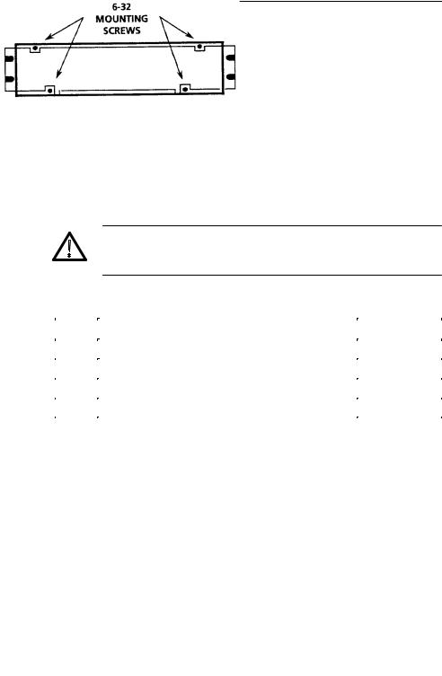
Figure 1±1: Location of the four screws that secure the instrument to rack-mounting cabinet or portable case
WARNING. Do not attempt to carry a cabinetized instrument without installing the rear-panel mounting screws. There is nothing to hold the instrument in the cabinet if it is tipped forward.
Table 1±1: Rack-Mounting Hardware Included
Qty |
Description |
Part Number |
|
|
|
2 |
Bracket, Extension: 2.5 X 8.06 X 0.06, Steel |
407-3752-00 |
|
|
|
2 |
Nut Bar: (3) 10-32 X 3.0 X 0.375 X 0.125, Aluminum |
381-0251-00 |
|
|
|
12 |
Screw, Machine: 10-32 X 0.625, Steel |
212-0577-00 |
|
|
|
4 |
Washer, Flat: 0.203 ID X 0.625 OD X 0.062, Steel |
210-1061-00 |
|
|
|
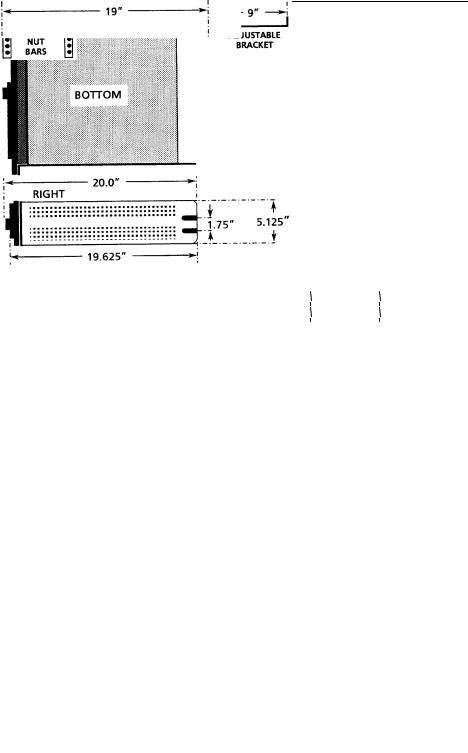
A front clearance of at least 18 inches is required for removing the instrument from the rack. BNC connectors on the rear panel extend approximately 0.6 inches, making it necessary to have 1 inch or more of rear clearance to have enough room to cable the instrument. See Figure 1±2 for rack-mounting dimensions.
1780R-Series Operator's Manual |
1±5 |
Getting Started
Figure 1±2: Dimensions used for rack-mounting the 1780R-Series Video Measurement Set
1±6 |
1780R-Series Operator's Manual |
Getting Started
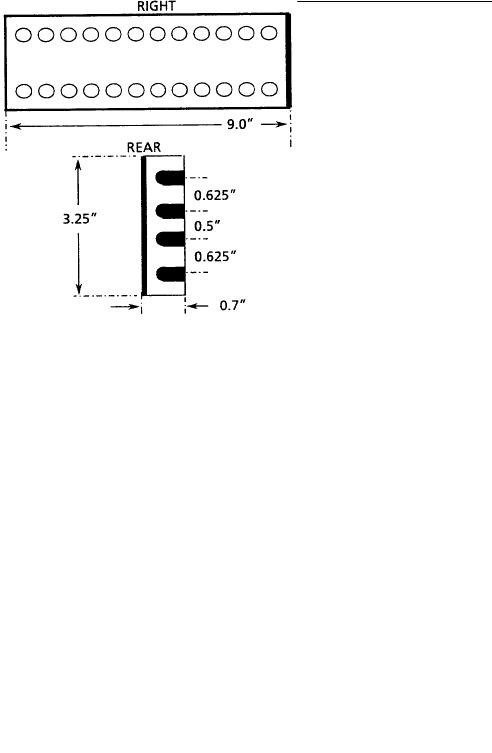
Figure 1±3: Dimensions of the adjustable rear rack-mounting bracket
To install the instrument in the rack: First remove the four securing screws and take the instrument out of the rack-mounting cabinet. (All 1780R-Series instruments are shipped in the rack-mounting cabinet to provide extra shipping protection.) Once the instrument is out of the cabinet, mount the front of the cabinet in the rack, using four 10±32 TORXR screws. Cabinet front slots are spaced, and wide enough, to accommodate standard racks. Next, mount the adjustable brackets to the rear rack section. See Figure 1±3 for bracket dimensions. Then mount the adjustable brackets to the rack-mount cabinet using four 10±32 TORXR screws, four number 10 flat washers, and the nut bars. See Figure 1±4 for more assembly detail. Finally, re-install the four 6±32 screws that secure the instrument to the rack-mounting cabinet. See Figure 1±1.
1780R-Series Operator's Manual |
1±7 |

Getting Started
Figure 1±4: Installing rear rack-mounting brackets for rack applications of depths from 18 to 24 inches
NOTE. For ease of installation, place the nut bars to the outside of the adjustable brackets and drive the screws from the center into the nut bars.
For applications where it is necessary to rack-mount the instrument, but have it removable with the instrument case, order the 1780F05 Rack-Mount Shelf.
1±8 |
1780R-Series Operator's Manual |

Getting Started
Options
The 1780R-Series is shipped with a standard U.S. plug, or can be ordered with one of the following options.
Option A1 (220 V, European plug)
Option A2 (240 V, United Kingdom plug)
Option A3 (240 V, Australian plug)
These are the only options currently available for the 1780R-Series. Part numbers are listed in Section 6.
Standard Accessories
The following accessories are shipped with the 1780R-Series. Part numbers are listed in Section 6.
1 1780R-Series Operator's Manual
1 Cable, Power (Standard, Opt A1, A2, or A3)
1 Filter, Air
1 Graticule, 511-1979, Visual (1780R ONLY)
1 Graticule, 511-1979, Photographic (1780R ONLY)
1 Graticule, K-Factor, Visual (1781R ONLY)
1 Graticule, K-Factor, Photographic (1781R ONLY)
3 Graticule Lamp, Incandescent
1 Replacement Cartridge Fuse, 2 A Slow Blow
1780R-Series Operator's Manual |
1±9 |

Getting Started
Optional Accessories
The following is a list of the most common accessory items for the 1780R-Series. Part numbers, if applicable, are listed in Section 6.
1780R-Series Service Manual
Viewing Hood
Portable Cabinet
Extender Kit for Oscillator and Z-Axis Circuit Boards
1±10 |
1780R-Series Operator's Manual |
Loading...