


 Loading...
User Manual
TR 210 Tracker 071-0114-01

Copyright © Tektronix, Inc. All rights reserved.
Tektronix products are covered by U.S. and foreign patents, issued and pending. Information in this publication supercedes that in all previously published material. Specifications and price change privileges reserved.
Printed in the U.S.A.
Tektronix, Inc., PO Box 500, Beaverton, OR 97077
TEKTRONIX and TEK are registered trademarks of Tektronix, Inc.
Huntron and Tracker are registered trademarks of Huntron, Inc.

WARRANTY
Tektronix warrants that the products that it manufactures and sells will be free from defects in materials and workmanship for a period of one (1) year from the date of purchase from an authorized Tektronix distributor. If any such product proves defective during this warranty period, Tektronix, at its option, either will repair the defective product without charge for parts and labor, or will provide a replacement in exchange for the defective product. Batteries are excluded from this warranty.
In order to obtain service under this warranty, Customer must notify Tektronix of the defect before the expiration of the warranty period and make suitable arrangements for the performance of service. Customer shall be responsible for packaging and shipping the defective product to the service center designated by Tektronix, shipping charges prepaid, and with a copy of customer proof of purchase. Tektronix shall pay for the return of the product to Customer if the shipment is to a location within the country in which the Tektronix service center is located. Customer shall be responsible for paying all shipping charges, duties, taxes, and any other charges for products returned to any other locations.
This warranty shall not apply to any defect, failure or damage caused by improper use or improper or inadequate maintenance and care. Tektronix shall not be obligated to furnish service under this warranty a) to repair damage resulting from attempts by personnel other than Tektronix representatives to install, repair or service the product; b) to repair damage resulting from improper use or connection to incompatible equipment; c) to repair any damage or malfunction caused by the use of non-Tektronix supplies; or d) to service a product that has been modified or integrated with other products when the effect of such modification or integration increases the time or difficulty of servicing the product.
THIS WARRANTY IS GIVEN BY TEKTRONIX WITH RESPECT TO THE LISTED PRODUCTS IN LIEU OF ANY OTHER WARRANTIES, EXPRESS OR IMPLIED. TEKTRONIX AND ITS VENDORS DISCLAIM ANY IMPLIED WARRANTIES OF MERCHANTABILITY OR FITNESS FOR A PARTICULAR PURPOSE. TEKTRONIX’ RESPONSIBILITY TO REPAIR OR REPLACE DEFECTIVE PRODUCTS IS THE SOLE AND EXCLUSIVE REMEDY PROVIDED TO THE CUSTOMER FOR BREACH OF THIS WARRANTY. TEKTRONIX AND ITS VENDORS WILL NOT BE LIABLE FOR ANY INDIRECT, SPECIAL, INCIDENTAL, OR CONSEQUENTIAL DAMAGES IRRESPECTIVE OF WHETHER TEKTRONIX OR THE VENDOR HAS ADVANCE NOTICE OF THE POSSIBILITY OF SUCH DAMAGES.

Contacting Tektronix
Product |
For application-oriented questions about a Tektronix measure- |
Support |
ment product, call toll free in North America: |
|
1-800-TEK-WIDE (1-800-835-9433 ext. 2400) |
|
6:00 a.m. – 5:00 p.m. Pacific time |
|
Or contact us by e-mail: |
|
tm_app_supp@tek.com |
|
For product support outside of North America, contact your |
|
local Tektronix distributor or sales office. |
Service |
Contact your local Tektronix distributor or sales office. Or visit |
Support |
our web site for a listing of worldwide service locations. |
|
http://www.tek.com |
For other |
In North America: |
information |
1-800-TEK-WIDE (1-800-835-9433) |
|
An operator will direct your call. |
To write us |
Tektronix, Inc. |
|
P.O. Box 500 |
|
Beaverton, OR 97077 |

Contents
General Safety Summary................................................................................ |
v |
Introduction and Specifications .................................................................. |
1-1 |
What is Signature Analysis?........................................................................... |
1-2 |
Power Configuration ...................................................................................... |
1-3 |
Signal Fuse Replacement................................................................................ |
1-4 |
50/60Hz Selector Switch ................................................................................ |
1-4 |
Unpacking Your TR 210 ................................................................................ |
1-4 |
Installation ...................................................................................................... |
1-5 |
Operating the TR 210 ..................................................................................... |
1-6 |
Specifications ................................................................................................. |
1-8 |
Accessories ..................................................................................................... |
1-12 |
A Quick Tour ................................................................................................ |
2-1 |
Front Panel...................................................................................................... |
2-2 |
Back Panel ...................................................................................................... |
2-4 |
Oscilloscope Display ...................................................................................... |
2-5 |
Initial Setups ................................................................................................... |
2-6 |
Power On ........................................................................................................ |
2-6 |
Range Selection .............................................................................................. |
2-6 |
Frequency Selection ....................................................................................... |
2-7 |
Channel Selection........................................................................................... |
2-7 |
Pulse Generator .............................................................................................. |
2-8 |
Using Your TR 210 ....................................................................................... |
3-1 |
Basics of ASA - How it Works ...................................................................... |
3-2 |
Horizontal Axis .............................................................................................. |
3-3 |
Vertical Axis................................................................................................... |
3-4 |
Basic Analog Signatures - Open and Short .................................................... |
3-5 |
Four Basic Component Analog Signatures .................................................... |
3-7 |
TR 210 User Manual |
i |

Contents
Testing Passive Components........................................................................ |
4-1 |
Resistors.......................................................................................................... |
4-1 |
Shorts and Opens, Resistor Faults .................................................................. |
4-4 |
Review ............................................................................................................ |
4-4 |
Troubleshooting Applications ........................................................................ |
4-5 |
Capacitors ....................................................................................................... |
4-6 |
Capacitor Analog Signatures .......................................................................... |
4-7 |
The Signatures of Different Capacitors in LOW2 Range............................... |
4-8 |
Understanding Capacitor Analog Signatures.................................................. |
4-9 |
Capacitor Failures - Leakage .......................................................................... |
4-10 |
Review ............................................................................................................ |
4-11 |
Applications .................................................................................................... |
4-11 |
Inductors ......................................................................................................... |
4-11 |
Inductor Analog Signatures ............................................................................ |
4-12 |
The Signatures of Different Inductors in LOW2 Range................................. |
4-13 |
Affect of Frequency Fs on Inductor Signatures .............................................. |
4-13 |
Understanding Inductive Signatures ............................................................... |
4-14 |
Review ............................................................................................................ |
4-14 |
Applications .................................................................................................... |
4-15 |
Electromechanical Switching Components .................................................... |
4-16 |
Manually Operated Mechanical Switches ...................................................... |
4-16 |
Review ............................................................................................................ |
4-18 |
Electomechanical Relays ................................................................................ |
4-18 |
Relay Coil Test ............................................................................................... |
4-18 |
Using the Pulse Generator to Test a 5V Reed Relay...................................... |
4-19 |
Review ............................................................................................................ |
4-20 |
Testing Discrete Semiconductors ................................................................ |
5-1 |
Diodes ............................................................................................................. |
5-1 |
Diode Analog Signatures ................................................................................ |
5-1 |
Affects of Frequency (Fs) on the Diode Signature ......................................... |
5-3 |
The Composite Diode Signature..................................................................... |
5-3 |
Diode Failures................................................................................................. |
5-4 |
Internal Resistance Flaw in a Diode ............................................................... |
5-5 |
Internal Leakage Flaw in a Diode................................................................... |
5-6 |
Zener Diodes................................................................................................... |
5-6 |
Review ............................................................................................................ |
5-8 |
Applications .................................................................................................... |
5-8 |
Transistors ...................................................................................................... |
5-9 |
Bipolar Transistor Signatures ......................................................................... |
5-9 |
Bipolar Transistor Base-Collector Signatures ................................................ |
5-10 |
Identifying Unknown Transistors ................................................................... |
5-12 |
Darlington Bipolar Transistor Signatures....................................................... |
5-14 |
Using the Pulse Generator to Test Transistor Operation................................ |
5-15 |
Analyzing the Active Characteristics of a Transistor ..................................... |
5-16 |
Review ............................................................................................................ |
5-17 |
Applications .................................................................................................... |
5-18 |
Optical Switches ............................................................................................. |
5-18 |
Phototransistors .............................................................................................. |
5-19 |
ii |
TR 210 User Manual |

Contents
Optocoupler Dynamic Testing........................................................................ |
5-20 |
Optocoupler Signatures .................................................................................. |
5-20 |
SCRs and Triacs ............................................................................................. |
5-22 |
Silicon Controlled Rectifiers (SCRs) ............................................................. |
5-22 |
Active Testing of an SCR............................................................................... |
5-24 |
Triacs .............................................................................................................. |
5-25 |
Active Testing of Triacs ................................................................................. |
5-26 |
Review ............................................................................................................ |
5-27 |
Applications.................................................................................................... |
5-27 |
Testing Integrated Circuits.......................................................................... |
6-1 |
Digital Integrated Circuits .............................................................................. |
6-1 |
Integrated Circuit Failures .............................................................................. |
6-1 |
Digital Integrated Circuit Signatures.............................................................. |
6-2 |
Signatures of a Digital IC ............................................................................... |
6-3 |
Signatures for Different Logic Chip Families ................................................ |
6-4 |
Comparing Two TTL Families....................................................................... |
6-4 |
CMOS Logic Family ...................................................................................... |
6-5 |
CMOS Components and Test Signal Frequency Fs........................................ |
6-7 |
Troubleshooting Digital Logic ICs................................................................. |
6-8 |
Comparison Testing for Digital ICs ............................................................... |
6-9 |
Review ............................................................................................................ |
6-10 |
Applications.................................................................................................... |
6-10 |
Analog Circuits............................................................................................... |
6-11 |
Op Amps......................................................................................................... |
6-11 |
Op Amp Signatures ........................................................................................ |
6-12 |
Troubleshooting Op Amp Circuits ................................................................. |
6-13 |
Linear Voltage Regulators.............................................................................. |
6-14 |
Review ............................................................................................................ |
6-15 |
Applications.................................................................................................... |
6-15 |
Low Voltage ................................................................................................... |
6-16 |
Review ............................................................................................................ |
6-18 |
Applications.................................................................................................... |
6-18 |
TR 210 User Manual |
iii |

Contents
iv |
TR 210 User Manual |

General Safety Summary
To Avoid Fire or Personal Injury
Review the following safety precautions to avoid injury and prevent damage to this product or any products connected to it. To avoid potential hazards, use this product only as specified.
Only qualified personnel should perform service procedures.
Use Proper Power Cord. Use only the power cord specified for this product and certified for the country of use.
Use Proper Voltage Setting. Before applying power, ensure that the line selector is in the proper position for the power source being used.
Connect and Disconnect Properly. Do not connect or disconnect probes or test leads while they are connected to a voltage source.
Ground the Product. This product is grounded through the grounding conductor of the power cord. To avoid electric shock, the grounding conductor must be connected to earth ground. Before making connections to the input or output terminals of the product, ensure that the product is properly grounded.
Observe All Terminal Ratings. To avoid fire or shock hazard, observe all ratings and markings on the product. Consult the product manual for further ratings information before making connections to the product.
Do not apply a potential to any terminal, including the common terminal, that exceeds the maximum rating of that terminal.
Do Not Operate Without Covers. Do not operate this product with covers or panels removed.
Use Proper Fuse. Use only the fuse type and rating specified for this product.
Avoid Exposed Circuitry. Do not touch exposed connections and components when power is present.
Do Not Operate With Suspected Failures. If you suspect there is damage to this product, have it inspected by qualified service personnel.
Do Not Operate in Wet/Damp Conditions.
Do Not Operate in an Explosive Atmosphere.
Keep Product Surfaces Clean and Dry.
TR 210 User Manual |
v |

General Safety Summary
Symbols and Terms Terms in this Manual. These terms may appear in this manual:
WARNING. Warning statements identify conditions or practices that could result in injury or loss of life.
CAUTION. Caution statements identify conditions or practices that could result in damage to this product or other property.
Terms on the Product. These terms may appear on the product:
DANGER indicates an injury hazard immediately accessible as you read the marking.
WARNING indicates an injury hazard not immediately accessible as you read the marking.
CAUTION indicates a hazard to property including the product.
Symbols on the Product. The following symbols may appear on the product:
vi |
|
|
TR 210 User Manual |
||
Introduction and Specifications
The Tektronix TR 210 is an accessory to an oscilloscope which allows power off troubleshooting of electronic circuits by using the technique of Analog Signature Analysis.
This signature shows the V/I characteristics of an electronic device which when compared with a known good device, can assist in locating faulty components of a circuit without applying power to the board under test. This technique of troubleshooting simply involves the visual comparison of circuit signatures which can assist in isolating circuit failures due to opens, shorts, device leakage, ESD damage, power supply over-voltage and transients.
Figure 1-1. TR 210
TR 210 User Manual |
1-1 |

Introduction and Specifications
What is Analog Signature Analysis?
Analog Signature Analysis or ASA is a unique, power-off troubleshooting technique. It uses an alternating current (AC) sinewave stimulus to show the current (I) vs. voltage (V) characteristic of an unpowered component on a CRT. The IV characteristic is called an analog signature and each pin of a component can have a unique signature. When components fail, their signatures change so troubleshooting using ASA is simply a matter of finding the defective component by analyzing its signature. You can compare signatures of suspect components to signatures of known-good components.
Test current applied across a component is limited. When used carefully, this technique is non-destructive and does not damage any components. ASA has many advantages as a proven, fast, and effective troubleshooting technique.
You can:
■Troubleshoot circuitry that cannot be powered up due to a shorted condition.
■Troubleshoot in a qualitative mode, allowing you to see physical problems with a suspect component.
■Compare device characteristics with known types for better matching.
■Eliminate risk of accidental shorting across other points during POWER ON testing which could further damage the component or other components on the board.
■Minimize the risk of shock hazard since the ASA troubleshooting approach requires no power applied to the circuitry.
■Perform preventative maintenance by seeing flaws in components that could possibly lead to untimely failures.
■Look at replacement components before they are installed in circuitry to reduce the risk of installing defective ones.
1-2 |
TR 210 User Manual |
Introduction and Specifications
|
|
The Tektronix TR 210 graphically displays the analog signature when connected |
|||||||||||||||||||||||||||
|
|
to two terminals of a component for visual interpretation. ASA may be |
|||||||||||||||||||||||||||
|
|
universally applied to any type of passive component like a resistor, capacitor, or |
|||||||||||||||||||||||||||
|
|
inductor, or a solid state semiconductor component like a diode, transistor, SCR, |
|||||||||||||||||||||||||||
|
|
digital, analog, or mixed-signal IC. When troubleshooting a board, the resultant |
|||||||||||||||||||||||||||
|
|
signature is a composite of various component signatures at a particular node in |
|||||||||||||||||||||||||||
|
|
the circuitry. By understanding what different signatures mean, you can |
|||||||||||||||||||||||||||
|
|
determine which components are faulty. |
|||||||||||||||||||||||||||
Power Configuration |
|
|
|
|
|
|
|
|
|
|
|
|
|
|
|
|
|
|
|
|
|
|
|
|
|
|
|
|
|
|
|
|
|
|
|
|
|
|
|
|
|
|
|
|
|
|
|
|
|
|
|
|
|
|
|
|
|
|
|
|
|
CAUTION. To avoid product damage, set the line selector switch to the correct |
|||||||||||||||||||||||||||
|
|
position and install the correct fuse before applying line power. |
|||||||||||||||||||||||||||
Line Selector Switch |
The Line Selector Switch, located on the TR 210’s back panel, selects between |
||||||||||||||||||||||||||||
|
|
100/115VAC and 230VAC. Slide the switch to the line voltage that you will be |
|||||||||||||||||||||||||||
|
|
using. |
|||||||||||||||||||||||||||
|
Line Fuse |
The power entry module on the TR 210 includes the power switch (0 = OFF, |
|||||||||||||||||||||||||||
|
|
1 = ON), power cord connector, and a removable tray which holds the line fuse |
|||||||||||||||||||||||||||
|
|
and a spare fuse. Make sure that replacement fuses are of the type and current |
|||||||||||||||||||||||||||
|
|
rating specified. If necessary, insert the specified line fuse (see line fuse |
|||||||||||||||||||||||||||
|
|
specification on page 1-9) into the fuse tray. |
|||||||||||||||||||||||||||
|
|
|
|
|
|
|
|
|
|
|
|
|
|
|
|
|
|
|
|
|
|
|
|
|
|
|
|
|
|
|
|
|
|
|
|
|
|
|
|
|
|
|
|
|
|
|
|
|
|
|
|
|
|
|
|
|
|
|
|
|
|
|
|
|
|
|
|
|
|
|
|
|
|
|
|
|
|
|
|
|
|
|
|
|
|
|
|
|
|
|
|
|
|
|
|
|
|
|
|
|
|
|
|
|
|
|
|
|
|
|
|
|
|
|
|
|
|
|
|
|
|
|
|
|
|
|
|
|
|
|
|
|
|
|
|
|
|
|
|
|
|
|
|
|
|
|
|
|
|
|
|
|
|
|
|
|
|
|
|
|
|
|
|
|
|
|
|
|
|
|
|
|
|
|
|
|
|
|
|
|
|
|
|
|
|
|
|
|
|
|
|
|
|
|
|
|
|
|
|
|
|
|
|
|
|
|
|
|
|
|
|
|
|
|
|
|
|
|
|
|
|
|
|
|
|
|
|
|
|
|
|
|
|
|
|
|
|
|
|
|
|
|
|
|
|
|
|
|
|
|
|
|
|
|
|
|
|
|
|
|
|
|
|
|
|
|
|
|
|
|
|
|
|
|
|
|
|
|
|
|
|
|
|
|
|
|
|
|
|
|
|
|
|
|
|
|
|
|
|
|
|
|
|
|
|
|
|
|
|
|
|
|
|
|
|
|
|
|
|
|
|
|
|
|
|
|
|
|
|
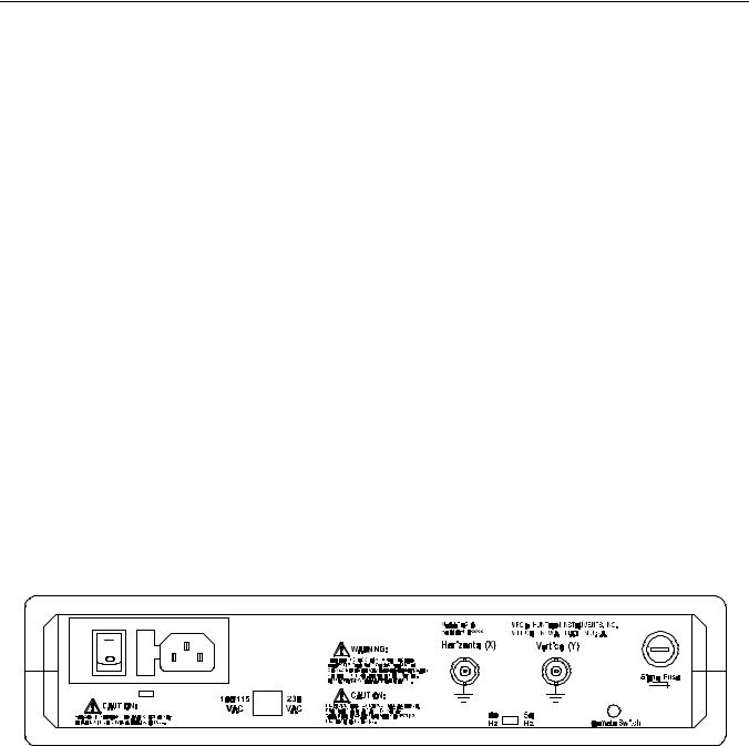
Figure 1-2. Back panel.
The line fuse should only open when there is a failure inside the instrument. Therefore the problem should always be located and corrected before fuse replacement. Be sure to always use a fuse with the type and rating specified on page 1-9.
TR 210 User Manual |
1-3 |

Introduction and Specifications
Signal Fuse Replacement
The Signal fuse is located on the back panel of the TR 210 in a panel mounted fuse holder. If the fuse opens, replace it with another 5 mm x 20 mm, F250 mA 250 V (IEC127-2/II type GDB) fuse.
50/60Hz Selector Switch
The 50/60Hz Selector Switch, located on the TR 210 back panel, is for indicating to the TR 210 what your line frequency is. Slide the switch to the setting that matches your line frequency.
Unpacking Your TR 210
Your instrument was shipped with the following items:
Table 1-2. TR 210 Shipping and Replaceable Parts List
Part Number |
Description |
Quantity |
|
|
|
ATL25 |
Tracker Probes |
1 pair |
98-0043* |
Black Ground Leads |
2 |
98-0270* |
Blue Clip Leads |
2 |
161-0230-01 |
Power Cord (115V) † |
1 |
071-0114-XX |
TR 210 User Manual † |
1 |
* Replacements available from Huntron, Inc. See page 1-12 for ordering information.
† Options add international power cords and translated manuals.
Check the shipment carefully and contact the place of purchase if anything is missing. If there is shipping damage, then contact your freight company. If shipment is necessary, please use the original shipping carton and packing foam. If these are not available, be sure that the instrument is packed in a box with a minimum of two inches (5 cm) of cushioning material on all sides.
1-4 |
TR 210 User Manual |
Introduction and Specifications
Installation
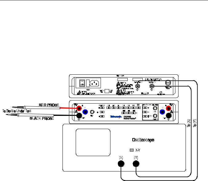
The TR 210 requires a 2 channel Oscilloscope with X/Y capability for displaying the signature of the device under test.
1.The figure below shows a typical connection of a TR 210 to an oscilloscope.
Figure 1-3. Typical TR 210-to-Oscilloscope connection.
2.Using BNC cables, connect the first oscilloscope channel 1 or X to the Horizontal (X) channel of the TR 210. Connect the second oscilloscope channel 2 or Y to the Vertical (Y) channel of the TR 210.
3.Connect the power cord to the TR 210 and switch the unit on.
TR 210 User Manual |
1-5 |

Introduction and Specifications
4. Setup the oscilloscope as follows:
1 V/div vertical scale on each channel
5 ms/div time base Trigger on channel 1 X/Y mode
The TR 210 will be in the LOW2 range. Adjust the Horizontal position so that the open circuit trace which should be a horizontal line is at the horizontal crosshair of the graticule. Connect the test probes to the front panel A and COM terminals of the TR 210. Short the test terminals. A vertical Trace will be displayed. Adjust the vertical position of the trace so that it is at the vertical crosshair of the graticule.
5. You are now ready to use the TR 210.
Operating the TR 210
1.To select a test range, press one of the five range buttons.
2.To select a test frequency, press one of the three frequency buttons. All test ranges will then be using the selected frequency.
3.To compare two devices, connect the test terminal of channel A to the reference or good device. Plug the banana jack of a second test probe to the channel B test terminal. See Figure 1-4 for instructions on adjusting the probe tips. Connect the test probe to the suspect device. Connect the common lead to one of the COM terminals. Press the ALT button and set the speed at which channel A and B will switch by turning the RATE knob. The signature of Channel A will alternate with the signature of channel B for an easy visual comparison of the two signatures.
1-6 |
TR 210 User Manual |

Introduction and Specifications
Figure 1-4. Adjusting the Probe Tips.
4.To avoid pressing each one of the test ranges, press the SCAN button. This will scan through all the test ranges one at a time.
5.The pulse generator is used to test gate fired devices like SCRs and Triacs. By connecting the G1 terminal to the gate of the device and applying the test terminal across the anode and cathode of the device, it is possible to actually turn the device on and look at the V/I characteristics of the device. This is particularly useful for power supplies where you are unable to turn on devices because the power supply is faulty on power up.
6.Refer to later chapters of this manual for details on testing resistors, capacitors, inductors, diodes, multiple component circuits, integrated circuits, SCRs and optocouplers.
TR 210 User Manual |
1-7 |

Introduction and Specifications
Specifications
The specifications for the TR 210 are listed in Table 1-1.
Table 1-1. TR 210 Specifications
Electrical
Test Signal: |
Sine wave |
Open Circuit Voltage (VS): |
60 Vpk HIGH Range |
|
20 Vpk MED 2 Range |
|
15 Vpk MED 1 Range |
|
10 Vpk LOW 2 Range |
|
3 Vpk LOW 1 Range |
Source Resistance (RS): |
74 kΩ HIGH Range |
|
27.6 kΩ MED 2 Range |
|
1.24 kΩ MED 1 Range |
|
54 Ω LOW 2 Range |
|
10 kΩ LOW 1 Range |
Frequency (FS): |
50/60 Hz |
|
200 Hz |
|
2000 Hz |
Channels: |
|
Number |
2 |
Display modes |
A, B, Alt |
Overload Protection |
Fuse: 5 mm x 20 mm, F250 mA, 250 V |
|
(IEC 127-2/II, type GDB) |
Overvoltage Category |
CAT I |
Pulse Generator: |
|
Number of Outputs: |
2 |
Level |
0 V to +/- 5 V, open circuit |
DC Mode |
+/- DC Level |
Pulse Mode |
+/- or Composite |
Frequency |
Matches selected test signal frequency |
Width (pulse mode) |
2% to 50% duty cycle |
Source resistance |
100 Ω each output |
Short circuit current |
50 mA max. each output |
1-8 |
TR 210 User Manual |

Introduction and Specifications
Table 1-1. TR 210 Specifications (continued)
Electrical (continued):
Power Requirements: |
|
|
Line Voltage |
100/115 VAC or 230 VAC |
|
Frequency |
50 Hz to 60 Hz |
|
Power |
15 W maximum |
|
Line Fuse |
100/115 V: 5 mm x 20 mm, T160 mA, 250 V |
|
|
|
(IEC127-2/III, type GDC) |
|
230 V: |
5 mm x 20 mm, T160 mA, 250 V |
|
|
(IEC127-2/III, type GDC) |
Mechanical |
|
|
Dimensions |
11.5” W x 2.7” H x 10.2” D |
|
|
(29.1 cm W x 6.9 cm H x 25.9 cm D) |
|
Weight |
4.6 lbs (2.1 kg) |
|
Shipping Weight |
approx. 7 lbs (3.0 kg) |
|
Environmental |
|
|
|
|
|
Indoor Use |
|
|
Altitude |
<2000m (<6560') |
|
Temperature |
|
|
Operating |
0°C to +40°C (32°F to 104°F) |
|
Storage |
-50°C to +60°C (-58°F to 140°F) |
|
Relative Humidity |
< 80% up to 31°C, |
|
|
derated linearly to 50% at 40°C |
|
TR 210 User Manual |
1-9 |

Introduction and Specifications
Table 1-1. TR 210 Specifications (continued)
Certifications and Compliances
EC Declaration of Conformity - EMC Directive |
Meets the intent of Directive 89/336/EC for |
|
Electromagnetic Compatibility. Compliance |
|
was demonstrated to the following |
|
specifications as listed in the Official Journal of |
|
the European Communities: |
|
EN 50081-1 Emissions: |
|
EN 55011 Class B Radiated and |
|
Conducted Emissions |
|
EN 50082-1 Immunity: |
|
IEC1000-4-2 Electrostatic Discharge |
|
IEC1000-4-3 RF Electromagnetic |
|
Field |
|
IEC1000-4-4 Electrical Fast Transient/ |
|
Burst |
|
IEC1000-4-5 Power Line Surge |
EC Declaration of Conformity - Low Voltage |
Compliance was demonstrated to the following |
Directive |
specification as listed in the Official Journal of |
|
the European Communities: |
|
Low Voltage Directive 73/23/EEC, as |
|
ammended by 93/68/EEC |
|
EN 61010-1:1993 |
|
Safety requirements for electrical |
|
equipment for measurement, |
|
control, and laboratory use |
1-10 |
TR 210 User Manual |
Introduction and Specifications
Table 1-1. TR 210 Specifications (continued)
Certifications and Compliances (continued)
Approvals |
UL3111-1 Standard for electrical measuring |
|
and test equipment |
|
CAN/CSA C22.2 No. 1010.1 Safety |
|
requirements for electrical equipment for |
|
measurement, control, and laboratory use |
Installation Category Descriptions |
Terminals on this product may have different |
|
category designations. The installation |
|
categories are: |
|
CAT III - Distribution-level mains (usually |
|
permanently connected). Equipment at this |
|
level is typically in a fixed industrial location. |
|
CAT II - Local-level mains (wall sockets). |
|
Equipment at this level includes appliances, |
|
portable tools, and similar products. Equipment |
|
is usually cord connected. |
|
CAT I - Secondary (signal level) or battery |
|
operated circuits of electronic equipment. |
Pollution Degree |
2 |
NOTE. Tektronix does not offer a Certificate of Traceable Calibration for the TR 210. The TR 210 is a troubleshooting tool and is not intended for use in calibration or conformance-testing applications.
TR 210 User Manual |
1-11 |

Introduction and Specifications
Accessories
You can order a foot switch (part number 98-0314) and other replacement parts from Huntron, Inc., at the address below:
Huntron, Inc.
15720 Mill Creek Blvd.
Mill Creek, WA 98012 U.S.A.
phone: 425-743-3171, or 1-800-426-9265 in the U.S.A.
The foot switch connects to the back panel of the TR 210. When the switch is depressed, the next test range is automatically selected. Using the foot switch is a convenient way of avoiding having to manually select the test range on the
TR 210 front panel.
1-12 |
TR 210 User Manual |

A Quick Tour
The Tektronix TR 210 is a versatile troubleshooting tool having the following features:
■Four test ranges and an additional low voltage (3 Volt) range for Low Power Surface Mounted devices.
■Two-channel pulse generator allowing the testing of gate fired devices.
■Three test frequencies to expand the range capability for testing capacitors and inductors.
■Two-channel compairson mode allowing the automatic switching between the reference signature and the suspect signature.
■Easy hookup to an oscilloscope with X/Y capability for displaying the signatures.
The TR 210 tests components using a two terminal system (three terminal system when the built-in pulse generator is used) where two leads are placed on the leads of the component under test. The TR 210 tests components in-circuit, even when there are several components in parallel.
All voltage sources in boards and systems must be in a power-off condition when using the TR 210. Electronic protection is a signal fuse connected in series with the channel A and B test terminals. Accidental contact of the test leads to active voltage sources, for example, line voltage, powered-up boards or systems, charged high voltage capacitors, etc., may cause the signal fuse to open. An open signal fuse is indicated by channel A and B showing a short-circuit signature at all times regardless if anything is connected across the probes. When this condition occurs, follow the directions in Signal Fuse Replacement on page 1-4 for replacing the signal fuse.
CAUTION. The device to be tested must have all power turned off, and have all high voltage capacitors discharged before connecting the TR 210 to the device.
TR 210 User Manual |
2-1 |

A Quick Tour
Before you begin to use the TR 210, please take a few minutes to familiarize yourself with the instrument. All of the externally accessible features are discussed in the following sections.
Front Panel
The front panel of the TR 210 is designed to ease access to its many features. All buttons are momentary action type and most have adjacent LED indicators to show which functions are active. Refer to Figure 2-1 and Table 2-1 for a detailed description of each item on the front panel.
Figure 2-1. TR 210 Front Panel With Callouts.
2-2 |
TR 210 User Manual |

A Quick Tour
Table 2-1. Front Panel Controls And Connections.
|
Name |
Function |
|
|
|
1 |
Range Selectors |
Push buttons that select one of five impedance |
|
|
ranges: LOW1, LOW2, MED1, MED2 and HIGH |
2 |
Scan Switch |
Push button that initiates automatic scanning of the |
|
|
five ranges from LOW1 to HIGH. The scanning |
|
|
speed is determined by the RATE control (see item |
|
|
#9). |
3 |
Channel A Switch |
Selects channel A for display on the oscilloscope. |
4 |
Channel A Test Terminal |
Safety shrouded banana jack for channel A test |
|
|
signal. |
5 |
ALT Switch |
Causes the TR 210 to alternate between channel A |
|
|
and channel B at a speed determined by the RATE |
|
|
control (see item #9). |
6 |
COM Test Terminal |
Safety shrouded banana jack that is the instrument |
|
|
common and the common reference point for both |
|
|
channel A and channel B. |
7 |
Channel B Switch |
Selects channel B for display on the oscilloscope. |
8 |
Channel B Test Terminal |
Safety shrouded banana jack for channel B test |
|
|
signal. |
9 |
RATE Control |
Controls the speed of channel alternation and/or |
|
|
range scanning. |
10 |
G1 & G2 Terminals |
Pulse Generator dual outputs. |
11 |
WIDTH Control |
Controls the duty cycle of the pulse generator output. |
12 |
LEVEL Control |
Controls the amplitude of the pulse generator output. |
13 |
Pulse Generator Selectors |
Push buttons that select various output modes of the |
|
|
pulse generator: Positive(+), Negative (-) and |
|
|
PULSE/DC. |
14 |
Frequency Selectors |
Push buttons that select one of the three signal |
|
|
frequencies: 50/60 Hz, 200 Hz and 2000 Hz. |
15 |
NO HIGH range Switch |
Push button that activates a mode where it is not |
|
|
possible to enter the HIGH range either by manual or |
|
|
scan range selection. |
TR 210 User Manual |
2-3 |
A Quick Tour
Back Panel
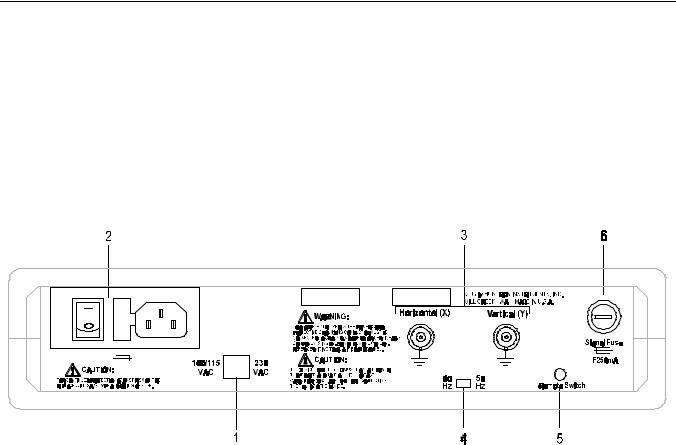
Secondary controls and connectors are on the back panel. Refer to Figure 2-2 and Table 2-2 for a detailed description of each item on the back panel
Figure 2-2. TR 210 Back Panel.
Table 2-2. Back Panel Connections.
|
Name |
Function |
|
|
|
1 |
Input Voltage Selector |
Select between 100/115 VAC and 230 VAC input |
|
|
voltage. |
2 |
Power cord connector |
IEC standard connector that mates with any CDD-22 |
|
Power fuse holder |
power cord. Power fuse holder and Power switch. |
|
Power switch |
|
3 |
X & Y output |
X & Y outputs connects to oscilloscope. |
4 |
Input Hz selector |
Select between 50 or 60 Hz input frequency |
5 |
Remote Switch |
Using the Foot Switch accessory, you can change to |
|
|
the next range in the scan sequence. |
6 |
Signal Fuse |
250 mA fuse. |
2-4 |
TR 210 User Manual |

A Quick Tour
Oscilloscope Display
The TR 210 uses the display of any oscilloscope that is capable of displaying an untriggered XY waveform. The oscilloscope display can be divided into four quadrants. Each quadrant displays different portions of the signatures. Quadrant 1 displays positive voltage (+V) and positive current (+I), quadrant 2 displays negative voltage (-V) and positive current (+I), quadrant 3 displays negative voltage (-V) and negative current (-I), and quadrant 4 displays positive voltage (+V) and negative current (-I).
Figure 2-3. Oscilloscope Display.
TR 210 User Manual |
2-5 |

A Quick Tour
Initial Setups
The following setups assume that the TR 210 has been connected to an oscilloscope and the TR 210s power cord has been plugged into an appropriate wall socket.
Power On
Turn the power on to your TR 210 using the power switch located on the rear panel. The TR 210 should come on with the LEDs for channel A, 50/60 Hz, LOW2 range and Pulse/DC illuminated.
Range Selection
The TR 210 is designed with five impedance ranges (LOW1, LOW2, MED1, MED2 and HIGH). These ranges are selected by pressing the appropriate button on the front panel. It is best to start with one of the medium ranges (i.e. MED1 or MED2). If the signature on the oscilloscope display is close to an open (horizontal trace), go to the next higher range for a more descriptive signature. If the signature is close to a short (vertical trace), go to the next lower range.
NOTE: In HIGH range, up to 60 Vpk is present on the A and B test terminals. When using the HIGH range, be careful not to touch probe tips or any circuits connected to the A or B test terminals.
The NO HIGH lock feature, when activated, prevents the instrument from entering the HIGH range in either the manual or scan mode.
The scan feature scans through the five ranges (four with the NO HIGH lock activated) at a speed set by the RATE control This feature allows the user to see the signature of a component in different ranges while keeping hands free to hold the test leads.
2-6 |
TR 210 User Manual |

A Quick Tour
Frequency Selection
Three test frequencies can be selected by pressing the appropriate button on the front panel.
The 50/60 Hz button selects either 50 or 60 Hz depending on the position of the rear-panel switch. Set this switch to match the local power line frequency in use. In most cases this selection is the best one to use for general troubleshooting.
The 200 Hz button selects 200 Hz as the test signal frequency. This frequency also allows you to see smaller values of capacitance. The 2000 Hz button selects 2000 Hz as the test signal frequency. This frequency allows you to see even smaller values of capacitance.
The 200 Hz or 2000 Hz frequency selections may require you to adjust the oscilloscope time base to optimize the display.
Channel Selection
There are two test signal channels in the TR 210, Channel A and Channel B. There are three buttons, Alt, A and B to select what channel will be displayed on the oscilloscope.
Before you view an analog signature on the TR 210, make sure that the analog signature is displayed in the correct quadrants on the display by following this procedure. When using a single channel, plug the red test probe into the corresponding channel test terminal and plug the black test probe into the common test terminal. When testing solid state or polarity sensitive components, place the red test probe to its positive terminal (i.e., anode, +V, etc.) and place the black probe to its negative terminal (i.e. cathode, -V, ground, etc.).
Push the corresponding channel button, A or B to view a single analog signature.
Push the Alt button to enable the Alternate display mode of the TR 210. This mode provides an automatic alternating display of channel A and channel B. It's easy to make a visual comparison of analog signatures for two of the same components or the same node points on two identical circuit boards when in Alt mode. Alternate display mode is one of the most useful features for comparing a known good device with a unknown device of the same type. The alternation frequency is varied by the RATE control. Refer to Figure 2-4 for an example on how to connect your test leads for comparison testing.
TR 210 User Manual |
2-7 |

A Quick Tour
Figure 2-4. Comparison Testing with Alternate Display Mode.
Pulse Generator
The pulse generator is used to drive the control input of a device under test which provides a dynamic test for certain types of devices. The normal two terminal mode of using the TR 210 can be thought of as a static test since devices with three or more terminals are not tested in their active state. However, with the pulse generator, an in-circuit active test of a device is possible. Figure 2-5 shows the equivalent circuit of the pulse generator and the signal section with the display connections remove for clarity.
Figure 2-5. Pulse Generator/Signal section Equivalent Circuit.
2-8 |
TR 210 User Manual |
Loading...