


THS720P

Service Manual
THS710A, THS720A,
THS730A & THS720P
TekScopet
070-9752-02
This document applies to to serial number
B010100 and above and firmware version 1.00
and above.
First printing: February 1998
Warning
The servicing instructions are for use by qualified
personnel only. To avoid personal injury, do not
perform any servicing unless you are qualified to
do so. Refer to all safety summaries prior to
performing service.

Copyright © Tektronix. All rights reserved. Licensed software products are owned by Tektronix or its subsidiaries or
suppliers, and are protected by national copyright laws and international treaty provisions.
Tektronix products are covered by U.S. and foreign patent s, issued and pending. Information in this publication supercedes
that in all previously published material. Specifications and price change privileges reserved.
TEKTRONIX and TEK are registered trademarks of Tektronix, Inc.
Tek Secure is a registered trademark of Tektronix, Inc.
TekTools, TekScope, and IsolatedChannel are trademarks of Tektronix, Inc.
Pursuant to DFARS 252.227-7013(e), Tektronix Inc. hereby grants to the Government a nonexclusive, paid-up license
throughout the world of the scope set forth therein for Government purposes for any commercial manuals provided by
Tektronix Inc. under this contract.
Contacting Tektronix
Tektronix, Inc.
14200 SW Karl Braun Drive
P.O. Box 500
Beaverton, OR 97077
USA
For product information, sales, service, and technical support:
H In North America, call 1-800-833-9200.
H Worldwide, visit www.tektronix.com to find contacts in your area.

Warranty 16
Tektronix warrants that the product will be free from defects in materials and workmanship for a period of thre e
(3) years from the date of original purchase from an authorized Tektronix distributor. If the product proves
defective during this warranty period, Tektronix, at its option, either will repair the defective product without
charge for parts and labor, or will provide a replacement in exchange for the defective product. Batteries are
excluded from this warranty. Parts, modules and replacement products used by Tektronix for warranty work may
be new or reconditioned to like new performance. All replaced parts, modules and products become the property
of Tektronix.
In order to obtain service under this warranty, Customer must notify Tektronix of the defect before the expiration
of the warranty period and make suitable arrangements for the performance of service. Customer shall be
responsible for packaging and shipping the defective product to the service center designated by Tektronix,
shipping charges prepaid, and with a copy of customer proof of purchase. Tektronix shall pay for the return of the
product to Customer if the shipment is to a location within the country in which the Tektronix service center is
located. Customer shall be responsible for paying all shipping charges, duties, taxes, and any other charges for
products returned to any other locations.
This warranty shall not apply to any defect, failure or damage caused by improper use or improper or inadequate
maintenance and care. Tektronix shall not be obligated to furnish service under this warranty a) to repair damage
resulting from attempts by personnel other than Tektronix representatives to install, repair or service the product;
b) to repair damage resulting from improper use or connection to incompatible equipment; c) to repair any
damage or malfunction caused by the use of non-Tektronix supplies; or d) to service a product that has been
modified or integrated with other products when the effect of such modification or integra tion increases the time
or difficulty of servicing the product.
THIS WARRANTY IS GIVEN BY TEKTRONIX WITH RESPECT TO THE PRODUCT IN LIEU OF ANY
OTHER WARRANTIES, EXPRESS OR IMPLIED. TEKTRONIX AND ITS VENDORS DISCLAIM ANY
IMPLIED WARRANTIES OF MERCHANTABILITY OR FITNESS FOR A PARTICULAR PURPOSE.
TEKTRONIX’ RESPONSIBILITY TO REPAIR OR REPLACE DEFECTIVE PRODUCTS IS THE SOLE AND
EXCLUSIVE REMEDY PROVIDED TO THE CUSTOMER FOR BREACH OF THIS WARRANTY.
TEKTRONIX AND ITS VENDORS WILL NOT BE LIABLE FOR ANY INDIRECT, SPECIAL, INCIDENTAL,
OR CONSEQUENTIAL DAMAGES IRRESPECTIVE OF WHETHER TEKTRONIX OR THE VENDOR HAS
ADVANCE NOTICE OF THE POSSIBILITY OF SUCH DAMAGES.


THS710A, THS720A, THS730A & THS720P Service Manual
i
Table of Contents
General Safety Summary v...................................
Service Safety Summary vii....................................
Preface ix...................................................
Related Manuals ix.................................................
Conventions x....................................................
Specifications 1.............................................
Operating Information 15.....................................
Internal and External Power Sources 15.................................
Understanding the Front Panel 17......................................
Connecting and Using the Probes 22...................................
Theory of Operation 25.......................................
Main Board 25.....................................................
Inverter Board 25...................................................
Display Module 26.................................................
Switch Assembly 26................................................
Performance V erification 27...................................
Test Record 28.....................................................
Performance Verification Procedures 30.................................
Adjustment Procedures 51.....................................
Required Equipment 51..............................................
Overview of the Adjustment Process 52.................................
Accessing the Adjustment-Lockout Jumper 53...........................
Oscilloscope Adjustment 55..........................................
Meter Adjustment 58................................................
Replacing the Adjustment-Lockout Jumper 61............................
Maintenance 63..............................................
Preparation 63.....................................................
Preventing ESD 63.................................................
Inspection and Cleaning 64...........................................
Removal and Installation Procedures 67.................................
Troubleshooting 90.................................................
Unpacking and Repacking Instructions 102...............................
Options 103..................................................
Electrical Parts List 105........................................
Diagrams 107.................................................
Mechanical Parts List 109......................................
Parts Ordering Information 109.........................................
Using the Replaceable Parts List 110....................................

Table of Contents
ii
THS710A, THS720A, THS730A & THS720P Service Manual
List of Figures
Figure 1: Removing and replacing the battery 16..................
Figure 2: AC adapter attachment 16.............................
Figure 3: Typical scope-mode display 17.........................
Figure 4: Typical meter-mode display 18.........................
Figure 5: Connector locations 22................................
Figure 6: Module-level block diagram 26.........................
Figure 7: Location of adjustment-lockout jumper 54...............
Figure 8: Oscilloscope adjustment setups 56......................
Figure 9: Meter adjustment setups 59...........................
Figure 10: Relocating the adjustment-lockout jumper 61...........
Figure 11: Removing the tilt stand 70............................
Figure 12: Installing the tilt stand 71............................
Figure 13: Installing a new front-panel label 72...................
Figure 14: Removing the battery door 74.........................
Figure 15: Assembling a new front cover 75......................
Figure 16: Installing the gasket 76..............................
Figure 17: Installing the handle 77..............................
Figure 18: Removing the display module 79......................
Figure 19: Opening the display cable connector 80................
Figure 20: Routing cables to the inverter board 81.................
Figure 21: Lifting the chassis 82................................
Figure 22: Foam pad and hole plug locations on the back cover 83...
Figure 23: Routing the battery wires 84..........................
Figure 24: Removing the main board and switch flex-circuit
assembly 86..............................................
Figure 25: Foam pad locations on the chassis 87...................
Figure 26: Reassembling the chassis 89..........................
Figure 27: Battery connector location 91.........................
Figure 28: Bypassing the ON/STBY switch 93....................
Figure 29: Exploded diagram 113................................

Table of Contents
THS710A, THS720A, THS730A & THS720P Service Manual
iii
List of Tables
Table 1: Oscilloscope specifications 1..........................
T able 2: DMM specifications 8................................
T able 3: General specifications 10..............................
Table 4: Summary of oscilloscope adjustment steps 55.............
T able 5: Summary of meter adjustment steps 58..................
T able 6: Internal inspection check list 65........................
Table 7: Removal and installation procedures 68..................
Table 8: TekScope instrument options 103........................
T able 9: Replaceable standard accessories 114.....................

Table of Contents
iv
THS710A, THS720A, THS730A & THS720P Service Manual

THS710A, THS720A, THS730A & THS720P Service Manual
v
General Safety Summary
Review the following safety precautions to avoid injury and prevent damage to
this product or any products connected to it.
Only qualified personnel should perform service procedures.
Connect and Disconnect Properly. Do not connect or disconnect probes or test
leads while they are connected to a voltage source.
Ground the Product. This product is grounded through the grounding conductor
of the power cord. To avoid electric shock, the grounding conductor must be
connected to earth ground. Before making connections to the input or output
terminals of the product, ensure that the product is properly grounded.
Observe All Terminal Ratings. To avoid fire or shock hazard, observe all ratings
and markings on the product. Consult the product manual for further ratings
information before making connections to the product.
Do not apply a potential to any terminal, including the common terminal, that
exceeds the maximum rating of that terminal.
Replace Batteries Properly. Replace batteries only with the specified type and
rating.
Recharge Batteries Properly. Recharge batteries for the recommended charge
cycle only.
Use Proper AC Adapter. Use only the AC adapter specified for this product.
Do Not Operate Without Covers. Do not operate this product with covers or panels
removed.
Avoid Exposed Circuitry. Do not touch exposed connections and components
when power is present.
Do Not Operate With Suspected Failures. If you suspect there is damage to this
product, have it inspected by qualified service personnel.
Do Not Operate in Wet/Damp Conditions.
Do Not Operate in an Explosive Atmosphere.

General Safety Summary
vi
THS710A, THS720A, THS730A & THS720P Service Manual
These terms may appear in this manual:
WARNING. Warning statements identify conditions or practices that could result
in injury or loss of life.
CAUTION. Caution statements identify conditions or practices that could result in
damage to this product or other property.
These terms may appear on the product:
H DANGER indicates an injury hazard immediately accessible as you read the
marking.
H WARNING indicates an injury hazard not immediately accessible as you
read the marking.
H CAUTION indicates a hazard to property including the product.
The following symbol(s) may appear on the product:
CAUTION
Refer to Manual
WARNING
High Voltage
Double
Insulated
Protective Ground
(Earth) Terminal
Terms in this Manual
Symbols and Terms
on the Product

THS710A, THS720A, THS730A & THS720P Service Manual
vii
Service Safety Summary
Only qualified personnel should perform service procedures. Read this Service
Safety Summary and the General Safety Summary before performing any service
procedures.
Do Not Service Alone. Do not perform internal service or adjustments of this
product unless another person capable of rendering first aid and resuscitation is
present.
Use Care When Servicing With Power On. Dangerous voltages or currents may
exist in this product. Disconnect power, remove battery (if applicable), and
disconnect test leads before removing protective panels, soldering, or replacing
components.
To avoid electric shock, do not touch exposed connections.

Service Safety Summary
viii
THS710A, THS720A, THS730A & THS720P Service Manual

THS710A, THS720A, THS730A & THS720P Service Manual
ix
Preface
This is the Service Manual for the THS710A, THS720A, THS730A, and
THS720P TekScope instruments. This manual provides information to trouble-
shoot and repair the instrument to the module level.
Related Manuals
Additional documentation for the instrument is contained in the related manuals
listed below.
Language
User Manual
Part Number
Reference
Part Number
Programmer Manual
Part Number
English 070-9731-XX 070-9741-XX 070-9751-XX
French 070-9732-XX 070-9742-XX
German 070-9733-XX 070-9743-XX
Italian 070-9734-XX 070-9744-XX
Korean 070-9735-XX 070-9745-XX
Portuguese 070-9736-XX 070-9746-XX
Spanish 070-9737-XX 070-9747-XX
Simplified Chinese 070-9738-XX 070-9748-XX
Traditional
Chinese
070-9739-XX 070-9749-XX
Japanese 070-9740-XX 070-9799-00
Preface
x
THS710A, THS720A, THS730A & THS720P Service Manual
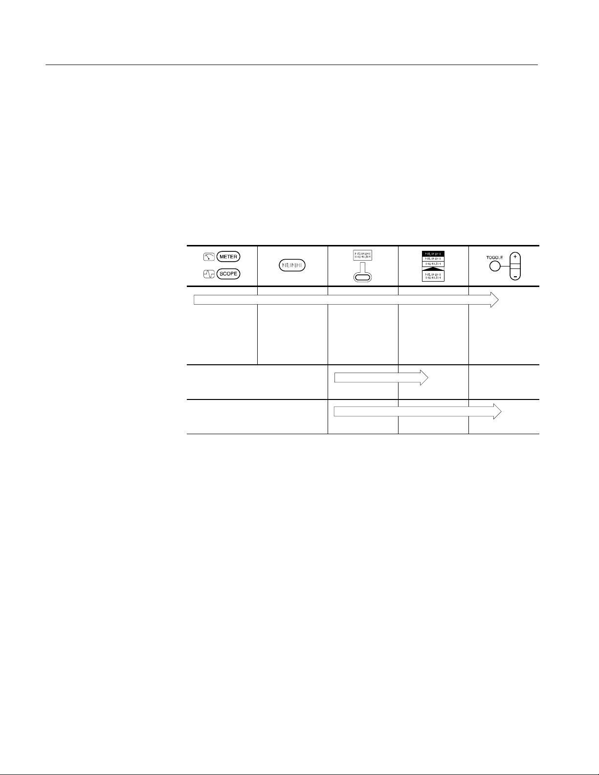
Conventions
In the Performance Verification, Adjustments,andMaintenance chapters of this
manual, TekScope instrument setups are shown in tables similar to the one
shown below.
The header of each table contains icons that represent the controls and menu
items used to set up the instrument. To make a specific setup, read the table from
left to right and then from top to bottom as shown below. The table contains the
symbol “—” if no action is required.
1. Choose scope
mode or meter
mode.
2. Press this but-
ton on the front
panel.
3. Press this
bezel button.
4. Press the
bezel button
again until this
selection is high-
lighted.
5. Use the
+
/-- rocker to set
the value for a
parameter.
6. 7. —
8. 9. 10.

THS710A, THS720A, THS730A & THS720P Service Manual
1
Specifications
This chapter contains the oscilloscope, DMM, and general specifications for the
THS710A, THS720A, THS730A, and THS720P TekScope instruments. All
specifications are guaranteed unless noted “typical.” Typical specifications are
provided for your convenience but are not guaranteed. Specifications that are
marked with the n symbol are checked in the chapter Performance Verification.
All specifications apply to all four instruments unless noted otherwise. All
specifications assume horizontal MAG is off, unless noted otherwise. To meet
specifications, two conditions must first be met:
H The TekScope instrument must have been operating continuously for ten
minutes within the operating temperature range specified.
H You must perform the Compensate Signal Path operation, accessible through
the utility menu, if the ambient temperature changes by more than 5° C.
Table 1: Oscilloscope specifications
Acquisition
Acquisition Modes Sample (Normal), Peak detect, Envelope, and Average
Acquisition Rate,
typical
Up to 25 waveforms per second (2 channels, sample acquisition mode,
MAG on, no measurements)
Single Sequence Acquisition Mode Acquisition Stops After
g
q
Sample, Peak Detect Single acquisition, one or two
channels simultaneously
Average, Envelope N acquisitions, one or two chan-
nels simultaneously, N is settable
from 2 to 256 or ∞
Inputs
Input Coupling DC, AC, or GND
Input Impedance,
DC Coupled
1MΩ ±1% in parallel with 25 pF ±2pF
Maximum Voltage Overvoltage Category Maximum Voltage
g
Between Signal and
Common at Input
CAT II Environment (refer to
page 13)
300 V
RMS
B
N
C
CAT III Environment (refer to
page 13)
150 V
RMS
For steady-state sinusoidal waveforms, derate at 20 dB/decade above
100 kHz to 13 V
pk
at 3 MHz and above. Also, refer to Overvoltage
Category description on page 13.

Specifications
2
THS710A, THS720A, THS730A & THS720P Service Manual
Table 1: Oscilloscope specifications (Cont.)
Inputs
Maximum Voltage
Between Common
and Earth Ground
at BNC
600 V
RMS
(CAT II) or 300 V
RMS
(CAT III), using rated connectors or
accessories
30 V
RMS
, 42.4 V
pk
, using noninsulated connectors and acessories
Maximum Voltage,
Channel-to-Channel
Commons
30 V
RMS
, 42.4 V
pk
, using noninsulated connectors and acessories
Channel-to-Channel
Common Mode
Rejection, typical
100:1 at frequencies ≤50 MHz, measured on MATH Ch1 -- Ch2
waveform, with test signal applied between signal and common of both
channels, and with the same VOLTS/DIV and coupling settings on each
channel
Channel-to-Channel
Crosstalk, typical
≥100:1 at 50 MHz, measured on one channel, with test signal applied
between signal and common of the other channel, and with the same
VOLTS/DIV and coupling settings on each channel
Common to Chassis
Capacitance, typical
55 pF
Vertical
Number of Channels 2
Digitizers 8 bit resolution, separate digitizers for each channel sample
simultaneously
VOLTS/DIV Range 5 mV/div to 50 V/div at input BNC
Polarity Normal and Invert
Position Range ±10 divisions
n Analog Bandwidth THS710A THS720A THS720P THS730A
g
at BNC, DC Coupled
(typical at 5 mV/div,
guaranteed at all
other settings)
60 MHz at input
BNC
100 MHz at
input BNC
(90 MHz above
35° C)
100 MHz at
input BNC
(90 MHz above
35° C)
200 MHz at
input BNC
(180 MHz
above 35° C)
Peak Detect or Enve-
lo
p
eB
a
ndwidth,
THS710A THS720A THS720P THS730A
l
o
p
e
B
a
n
d
w
i
d
t
h
,
typical (25 MS/s or
slower)
50 MHz
75 MHz 75 MHz 85 MHz
Analog Bandwidth
Limit, typical
Selectable between 20 MHz or full
Lower Frequency
Limit, AC Coupled,
typical
≤10 Hz at BNC, reduced by a factor of ten when using a 10X passive
probe
Rise Time at BNC, THS710A THS720A THS720P THS730A
,
typical
5.8 ns 3.5 ns 3.5 ns 1.75 ns

Specifications
THS710A, THS720A, THS730A & THS720P Service Manual
3
Table 1: Oscilloscope specifications (Cont.)
Vertical
Peak Detect or Enve-
lope Pulse Response,
typical
Captures 50% or greater amplitude of pulses ≥ 8nswide(≥ 20 ns wide
at 500 ns/div)
DC Gain Accuracy ±2% for Sample or Average acquisition mode
Position Accuracy ±[0.4% × |(position × volts/div)| + (0.1 div × volts/div)]
n DC Measurement Measurement Type Accuracy
Accuracy, Average
Acquisition Mode
Using ≥16 Wave-
Absolute voltage measurements ±[2% × |reading +
(position × volts/div)| +
(0.1 div × volts/div)]
f
o
r
m
s
Delta voltage between any two
waveforms acquired under same
setup
±[2% × |reading| +
(0.05 div × volts/div)]
DC Measurement
Accuracy, Sample
Acq. Mode, typical
±[2% × |reading + (position × volts/div)| + (0.15 div × volts/div) +
0.6 mV]
Horizontal
Sample Rate Range THS710A THS720A THS720P THS730A
p
g
5 S/s to
250 MS/s, in a
1.25, 2.5, 5
sequence
5 S/s to
500 MS/s, in a
1.25, 2.5, 5
sequence
5 S/s to
500 MS/s, in a
1.25, 2.5, 5
sequence
5S/sto1GS/s,
in a 1.25, 2.5, 5
sequence
Record Length 2500 samples for each channel
SEC/DIV Range THS710A THS720A THS720P THS730A
/
g
(including MAG)
10 ns/div to
50 s/div
5 ns/div to
50 s/div
5 ns/div to
50 s/div
2 ns/div to
50 s/div
n Sample Rate and
Delay Time Accuracy
±200 ppm over any ≥1 ms time interval
Delay Time Range Zero to 50 s
Internal Trigger
n Trigger Sensitivity, Coupling Sensitivity
g
g
y
,
Edge Trigger Type
(THS710A, THS720A,
and THS720P)
DC
0.35 div from DC to 50 MHz,
increasing to 1 div at 100 MHz
(90 MHz above 35° C)
n Trigger Sensitivity, Coupling Sensitivity
g
g
y
,
Edge Trigger Type
(THS730A)
DC 0.35 div from DC to 50 MHz,
increasing to 1.5 div at 200 MHz
(180 MHz above 35° C)

Specifications
4
THS710A, THS720A, THS730A & THS720P Service Manual
Table 1: Oscilloscope specifications (Cont.)
Internal Trigger
Trigger Sensitivity, Coupling Sensitivity
g
g
y
,
Edge Trigger Type,
NOISE REJ 3.5 times the DC-coupled limits
t
y
p
i
c
a
l
HF REJ 1.5 times the DC-coupled limit
from DC to 30 kHz, attenuates
signals above 30 kHz
LF REJ 1.5 times the DC-coupled limits
for frequencies above 1 kHz,
attenuates signals below 1 kHz
Trigger Level Range ±4 divisions from center of screen
Motor Trigger Level
Range (THS720P)
0.1 to 5 divisions from center screen, polarity depends on slope
selection
Trigger Level
Accuracy, typical
±0.2 divisions, for signals having rise and fall times ≥20 ns
SET LEVEL TO 50%,
typical
Operates with input signals ≥50 Hz
Width Range, Pulse
Trigger Type, typical
99 ns to 1 s, with resolution of 33 ns or approximately 1% of setting
(whichever is greater)
Width Tolerance
Range, Pulse Trigger
Type, typical
5%, 10%, 15%, or 20%
Sensitivity, Video
Trigger Type, typical
Composite video signal with negative sync pulse amplitude from 0.6
to 2.5 divisions
Signal Formats and
Field Rates, Video
Broadcast systems Supports NTSC, PAL, and
SECAM
,
Trigger Type
Interlaced
Trigger on selected line of odd
field, selected line of even field, or
any line
Non-interlaced Trigger on selected line or any line
Line Rates 15 kHz to 65 kHz, in five ranges
Holdoff Range 495 ns to 10 s
External Trigger
External Trigger, Max-
imum Input Voltage
600 V
RMS
CAT II or 300 V
RMS
CAT III (refer to page 13)
External Trigger
Coupling
DC only
External Trigger
Levels
+0.2 V or +2 V, selectable
External Trigger
Sensitivity
500 mV
p-p
fromDCto1MHz,increasingto1V
p-p
at 5 MHz, with
signal centered at selected trigger level

Specifications
THS710A, THS720A, THS730A & THS720P Service Manual
5
Table 1: Oscilloscope specifications (Cont.)
Measurements
Cursors Voltage difference between cursors (ΔV)
Time difference between cursors (ΔT)
Reciprocal of ΔTinHertz(1/ΔT)
Phase difference between cursors (ΔDegrees)
Automated
Measurements
Amplitude, Burst Width, Cycle Mean, Cycle RMS, Fall Time,
Frequency, High, Low, Max, Mean, Min, Negative Duty Cycle, Negative
Overshoot, Negative Width, Pk -- Pk, Period, Positive Duty Cycle,
Positive Overshoot, Positive Width, Rise Time, and RMS
Voltage and Current Harmonics (THS720P)
Number of Harmonics First 31 harmonics of signal with fundamental frequency between
30 Hz and 450 Hz
Harmonics Amplitude
Accuracy
Accuracies below are stated as a percent of the fundamental amplitude
and are valid only if peak-to-peak amplitude is ≥4 di v isions and number
of averages ≥16
Fundamental 2--11 12 -- 21 22 -- 31
±2.5% ±2.5% ±4% ±4%
Harmonics Phase Fundamental 2--11 12 -- 21 22 -- 31
Accuracy
— ±4 ° ±8 ° ±8 °
THD-F Measurement Total harmonic distortion relative to the fundamental amplitude
THD-F =
V
2
RMS
− V
2
f
Ꭹ
V
f
or
A
2
RMS
− A
2
f
Ꭹ
A
f
THD-F Accuracy ±4%
THD-R Measurement Total harmonic distortion relative to the RMS amplitude
THD-R =
V
2
RMS
− V
2
f
Ꭹ
V
RMS
or
A
2
RMS
− A
2
f
Ꭹ
A
RMS
THD-R Accuracy ±4%
Frequency Accuracy ±0.2% of reading
Power Measurements (THS720P)
True Power
Measurement
W =
1
n
×
ᒑ
n
V
n
× A
n
measured over an integral number of cycles that
contain n sample points
Apparent Power
Measurement
VA = V
RMS
× A
RMS
Reactive Power
Measurement
VAR = (VA)
2
− W
2
Ꭹ
Power Measurements
Accuracy
±4% at the BNCs (not including probe uncertainty)

Specifications
6
THS710A, THS720A, THS730A & THS720P Service Manual
Table 1: Oscilloscope specifications (Cont.)
Power Measurements (THS720P)
PF Measurement
Power factor (PF) =
true power
apparent power
=
W
VA
θ Measurement θ is the phase difference between the fundamental components of
voltage and current. Positive angle means voltage leads current.
Negative angle means voltage lags current.
DPF Measurement Displacement power factor (DPF) = cos θ
Power Factor Mea-
surements Accuracy
±0.05
With P6117 Probe
Analog Bandwidth, THS710A THS720A THS720P THS730A
g
,
DC Coupled
60 MHz 100 MHz
(90 MHz above
35° C)
100 MHz
(90 MHz above
35° C)
200 MHz
(180 MHz
above 35° C)
Probe Attenuation 10X
Maximum Voltage Overvoltage Category Maximum Voltage
g
Between Probe Tip
and Reference Lead
CAT II Environment (refer to
page 13)
300 V
RMS
CAT III Environment (refer to
page 13)
150 V
RMS
For steady-state sinusoidal waveforms, derate at 20 dB/decade above
900 kHz to 13 V
pk
at 27 MHz and above. Also, refer to Overvoltage
Category description on page 13.
Maximum Voltage
Between Reference
Lead and Earth
Ground Using P6117
Probe
30 V
RMS
, 42.4 V
pk
Maximum Voltage,
Channel-to-Channel
Reference Leads
Using P6117 Probe
30 V
RMS
, 42.4 V
pk

Specifications
THS710A, THS720A, THS730A & THS720P Service Manual
7
Table 1: Oscilloscope specifications (Cont.)
With P5102 Probe
Analog Bandwidth, THS710A THS720A THS720P THS730A
g
,
DC Coupled
60 MHz 100 MHz
(90 MHz above
35° C)
100 MHz
(90 MHz above
35° C)
100 MHz
Probe Attenuation 10X
Maximum Voltage Overvoltage Category Maximum Voltage
g
Between Probe Tip
and Reference Lead,
CAT II Environment (refer to
page 13)
1000 V
RMS
D
C
C
o
u
p
l
e
d
CAT III Environment (refer to
page 13)
600 V
RMS
Maximum Voltage
Overvoltage Category Maximum Voltage
g
Between Probe Tip
CAT II Environment ±1000 V
DC
a
n
d
R
e
f
e
r
e
n
c
e
L
e
a
d
,
AC Coupled
CAT III Environment
±600 V
DC
Maximum Voltage
Overvoltage Category Maximum Voltage
g
Between Re
f
eren
c
e
CAT II Environment 600 V
RMS
L
e
a
d
a
n
d
E
a
r
t
h
Ground
CAT III Environment 300 V
RMS

Specifications
8
THS710A, THS720A, THS730A & THS720P Service Manual
Table 2: DMM specifications
General
Resolution 3
3
⁄
4
digit, 4000 count full scale reading except as noted
Input Resistance, AC
or DC Voltage
10 MΩ ±10%
Input Capacitance,
AC or DC Voltage,
typical
≤100 pF
Maximum Voltage Overvoltage Category Maximum Voltage
g
Between DMM and
COM Inputs
CAT I Environment (refer to
page 13)
640 V
RMS
(880 V
DC
)
CAT II Environment (refer to
page 13)
600 V
RMS
CAT III Environment (refer to
page 13)
300 V
RMS
Maximum Voltage Overvoltage Category Maximum Voltage
g
Between DMM or
COM Input and Earth
CAT I Environment (refer to
page 13)
640 V
RMS
(880 V
DC
)
G
r
o
u
n
d
CAT II Environment (refer to
page 13)
600 V
RMS
CAT III Environment (refer to
page 13)
300 V
RMS
DC Voltage
Ranges and Range Resolution
g
Resolution
400.0 mV 0.1 mV
4.000 V 1mV
40.00 V 10 mV
400.0 V 100 mV
880 V 1V
n Accuracy ±(0.5% of reading + 5 counts)
Normal Mode
Rejection, typical
Rejects AC signals by >60 dB at 50 Hz or 60 Hz (user selectable)
Common Mode
Rejection, typical
Rejects AC signals by >100 dB at 50 Hz or 60 Hz (user selectable)

Specifications
THS710A, THS720A, THS730A & THS720P Service Manual
9
Table 2: DMM specifications (Cont.)
AC Voltage
Conversion Type AC conversions are true RMS. The AC measurement is based on the
AC and DC components of the signal as shown below:
AC Measurement = RMS(AC+DC) -- DC
Ranges and Range Resolution
g
Resolution
400.0 mV
0.1 mV
4.000 V 1mV
40.00 V 10 mV
400.0 V 100 mV
640 V 1V
n Accuracy Input Waveform Maximum Error
y
(40Hzto500Hz)
Sinusoidal waveforms ±(2% of reading + 5 counts)
Nonsinusoidal waveforms with
crest factor up to 3
±(4% of reading + 5 counts)
Common Mode
Rejection, typical
Rejects AC signals by >60 dB at DC, 50 Hz, and 60 Hz
Ω/Resistance
Ranges and Range Resolution
g
Resolution
400.0 Ω 0.1 Ω
4.000 kΩ 1 Ω
40.00 kΩ 10 Ω
400.0 kΩ 100 Ω
4.000 MΩ 1kΩ
40.00 MΩ 10 kΩ
n Accuracy Range Maximum Error
y
All ranges except 40 MΩ ±(0.5% of reading + 2 counts)
40 MΩ ±(2% of reading + 5 counts) for
≤60% relative humidity
Bias Voltage for Full Range Full Scale Bias Voltage
g
Scale Resistance
400.0 Ω 350 mV
M
e
a
suremen
t
,
t
y
p
i
c
a
l
4.000 kΩ 200 mV
40.00 kΩ 350 mV
400.0 kΩ 350 mV
4.000 MΩ 400 mV
40.00 MΩ 1.10 V

Specifications
10
THS710A, THS720A, THS730A & THS720P Service Manual
Table 2: DMM specifications (Cont.)
Ω/Resistance
Open Circuit Voltage, Range Open Circuit Voltage
p
g
,
typical
400.0 Ω 4.8 V
All other ranges ≤1.2 V
Continuity Check
Indication An audible tone is generated when measured resistance is below 50
Ω,typical
Open Circuit Voltage,
typical
4V
Test Current, typical 1mA
Diode Check
Range Zero to 2 V, measures forward voltage drop of semiconductor junction
Voltage Accuracy,
typical
±25%
Open Circuit Voltage,
typical
4V
Test Current, typical 1mA
Data Logger
Horizontal Scale
Range
30 s/div to 24 hours/div (4 minutes to 8 days, full scale)
Vertical Zoom Range 2X, 5X, or 10X
Table 3: General specifications
Display
Display Type 4.7 in (120 mm) diagonal liquid crystal
Display Resolution 320 horizontal by 240 vertical pixels
Display Contrast Adjustable, temperature compensated
Backlight Intensity,
typical
35 cd/m
2

Specifications
THS710A, THS720A, THS730A & THS720P Service Manual
11
Table 3: General specifications (Cont.)
RS-232 Interface
Device Type DTE. at RJ-45 connector
Pinout Signal Pin Number at
9-pin Null
Modem Adapter
Pin Number at
RJ-45
Connector
RTS out 1 8
TXD out 2 6
RXD in 3 5
GND 5 4
DTR out 6 3
CTS in 7 7
RTS out 8 8
DSR in (not used) 4 2
DCD in (not used) 7 1
Probe Compensator Output
Output Voltage,
typical
5.0 V into ≥1MΩ load
Frequency, typical 1.2 kHz
Power Source
Battery Replaceable Ni-Cd battery pack
Battery Life, typical Approximately two hours of continuous use from a full charge
Low Battery Indica-
tion, typical
Low battery message first appears approximately ten minutes before
the instrument powers off automatically
Battery Saver Standby Time-out and Backlight Time-out extend battery life. Time-out
ranges from 1 minute to 15 minutes, or off.
Battery Charging
Time, typical
With TekScope instrument operat-
ing
9 hours
,
y
p
With TekScope instrument turned
off
9 hours
In external charger 1.5 hours
External Power 12 VDC nominal, center positive; Operates with input from 10 VDC to
15 VDC
The DC INPUT disconnects itself automatically if >15 VDC is applied.
If this occurs, disconnect the overvoltage and then reconnect to a
voltage in the proper range.
Memory Retention,
typical
All memory is retained indefinitely with battery removed and without
external power applied.
Fuse This instrument has no user-replaceable fuses

Specifications
12
THS710A, THS720A, THS730A & THS720P Service Manual
Table 3: General specifications (Cont.)
Environmental
Temperature Operating -- 1 0 ° Cto+50° C
p
Nonoperating -- 2 0 ° Cto+60° C
Humidity +40° C or below ≤95% relative humidity
y
+41° Cto+50° C ≤75% relative humudity
Altitude Operating 2,000 m
Nonoperating 15,000 m
Random Vibration Operating 2.66 g
RMS
from 5 Hz to 500 Hz,
10 minutes on each axis
Nonoperating 3.48 g
RMS
from 5 Hz to 500 Hz,
10 minutes on each axis
Drop Resistance,
typical
Survives a 30 in (76 cm) drop onto concrete with only cosmetic damage
Moisture Resistance Meets IEC529, IP43 with DC input hole plug, I/O port hol e plug, and
battery door installed.
Mechanical
Size Height 8.53 in (217 mm)
Width 6.95 in (177 mm)
Depth 2.00 in (50.8 mm)
Weight With battery installed 3.2 lbs (1.5 kg)
g
With all standard accessories in
soft carry case
7.5 lbs (3.4 kg)
When packaged for domestic
shipment
9.0 lbs (4.1 kg)
Adjustment Interval
The recommended adjustment interval is one year

Specifications
THS710A, THS720A, THS730A & THS720P Service Manual
13
Table 3: General specifications (Cont.)
Certifications and Compliances
Certifications Listed UL3111-1 and CAN/CSA-C22.2 No. 1010.1-92, complies with
EN61010-1 /A2
Overvoltage Category Category Examples
g
g
y
CAT III A typical CAT III environment is
the power distribution system
within a building or factory. These
environments are somewhat
protected from lightning strikes,
but susceptible to switching
transients and other disturbances
that may generate high voltage
impulses.
CAT II A typical CAT II environment is
the 120/240 V distribution system
within a lab or office. These
environments are fairly well
protected from external high
voltage disturbances.
CAT I A typical CAT II environment is
circuitry inside electrical or elec-
tronic equipment that is powered
by a power supply or a battery.
EC Declaration of
Conformity
Meets the intent of Directive 89/336/EEC for Electromagnetic
Compatibility and Low-Voltage Directive 73/23/ECC for Product Safety
as ammended by 93/68/EEC. Compliance was demonstrated to the
following specifications as listed in the official Journal of the European
Communities:
EN 55011 Class A: Radiated and Conducted Emissions
13
EN 50081--1 Emissions:
EN 60555--2 Power Harmonics
EN 50082--1 Immunity:
IEC 801--2 Electrostatic Discharge
IEC 801--3 RF Radiated
2
IEC 801--4 Fast Transients
IEC 801--5 Surge
3
EN 61010--1 Safety
1
Tektronix-supplied ferrite bead required on instrument end of
RS-232 cable
2
Performance criteria: ≤ 5.0 div increase in peak to peak noise
(Sample acquisition mode, full bandwidth); otherwise, ≤ 1.0 div
increase in peak to peak noise
3
Applies to instrument operating with Tektronix-supplied AC
adapter

Specifications
14
THS710A, THS720A, THS730A & THS720P Service Manual

THS710A, THS720A, THS730A & THS720P Service Manual
15
Operating Information
This chapter provides a quick overview of the following topics:
H Internal and external power sources
H Understanding the front panel
H Connecting and using the probes
For more detailed information about TekScope instrument operation, refer to the
THS710A, THS720A, THS730A, & THS720P User Manual.
For information about unpacking and inspecting the instrument, refer to
Unpacking and Repacking Instructions on page 102 of this manual.
Internal and External Power Sources
You can power the TekScope instrument from the internal battery pack or from
the AC adapter (both are standard accessories).
Before using the battery for the first time, it must be charged. You can use
external power to charge the battery pack while it is in the TekScope instrument.
Or you can charge the battery pack with the optional external battery charger.
Typical battery charging times are listed below.
Configuration Typical Charging Time
Battery pack in TekScope instrument 9 hours
Battery pack in external charger 1.5 hours
You can remove and replace the battery pack without losing any saved
information. The current setup, saved setups, saved waveforms, and saved data
are stored in nonvolatile memory that does not depend on battery power. To
prevent loss of saved information, set the ON/STBY switch to STBY before
removing the battery pack. See Figure 1 for instruction to remove and replace the
battery.
WARNING. To avoid shock hazard, the battery door must remain closed in wet or
damp conditions.
Using the Battery Pack

Operator Information
16
THS710A, THS720A, THS730A & THS720P Service Manual
Battery pack
Figure 1: Removing and replacing the battery
For benchtop operation, you can use external power. Attach the AC adapter
as shown in Figure 2. The DC INPUT disconnects itself if an overvoltage is
applied. If this occurs, disconnect and then reconnect the AC adapter to resume
operation from external power.
WARNING. To avoid shock hazard, the DC input and I/O port hole plugs must
remain closed in wet or damp conditions.
External power to
DC INPUT
Figure 2: AC adapter attachment
Using External Power
 Loading...