


User Manual
TDS 200-Series
Digital Real-Time Oscilloscope
071-0398-03
This document supports firmware version FV:v1.00 and above.
www.tektronix.com

Copyright © Tektronix, Inc. All rights reserved.
Tektronix products are covered by U.S. and foreign patents, issued and pending. Information in this publication supercedes that in all previously published material. Specifications and price change privileges reserved.
Tektronix, Inc., P.O. Box 500, Beaverton, OR 97077
TEKTRONIX and TEK are registered trademarks of Tektronix, Inc.

WARRANTY SUMMARY
(TDS 200-Series Digitizing Oscilloscope)
Tektronix warrants that the products that it manufactures and sells will be free from defects in materials and workmanship for a period of three (3) years from the date of shipment from an authorized Tektronix distributor. If a product or CRT proves defective within the respective period, Tektronix will provide repair or replacement as described in the complete warranty statement.
To arrange for service or obtain a copy of the complete warranty statement, please contact your nearest Tektronix sales and service office.
EXCEPT AS PROVIDED IN THIS SUMMARY OR THE APPLICABLE WARRANTY STATEMENT, TEKTRONIX MAKES NO WARRANTY OF ANY KIND, EXPRESS OR IMPLIED, INCLUDING WITHOUT LIMITATION THE IMPLIED WARRANTIES OF MERCHANTABILITY AND FITNESS FOR A PARTICULAR PURPOSE. IN NO EVENT SHALL TEKTRONIX BE LIABLE FOR INDIRECT, SPECIAL OR CONSEQUENTIAL DAMAGES.

WARRANTY SUMMARY
(P2100 Probe)
Tektronix warrants that the products that it manufactures and sells will be free from defects in materials and workmanship for a period of one (1) year from the date of shipment. If a product proves defective within the respective period, Tektronix will provide repair or replacement as described in the complete warranty statement.
To arrange for service or obtain a copy of the complete warranty statement, please contact your nearest Tektronix sales and service office.
EXCEPT AS PROVIDED IN THIS SUMMARY OR THE APPLICABLE WARRANTY STATEMENT, TEKTRONIX MAKES NO WARRANTY OF ANY KIND, EXPRESS OR IMPLIED, INCLUDING WITHOUT LIMITATION THE IMPLIED WARRANTIES OF MERCHANTABILITY AND FITNESS FOR A PARTICULAR PURPOSE. IN NO EVENT SHALL TEKTRONIX BE LIABLE FOR INDIRECT, SPECIAL OR CONSEQUENTIAL DAMAGES.

Table of Contents |
|
General Safety Summary . . . . . . . . . . . . . . . . . . . . . . . . . . . . |
v |
Contacting Tektronix . . . . . . . . . . . . . . . . . . . . . . . . . . . . . . . . |
vii |
Product End-of-Life Handling . . . . . . . . . . . . . . . . . . . . . . . . |
viii |
Getting Started . . . . . . . . . . . . . . . . . . . . . . . . . . . . . . . . . . . . . |
1 |
General Features . . . . . . . . . . . . . . . . . . . . . . . . . . . . . . . . . . . . |
2 |
Installation . . . . . . . . . . . . . . . . . . . . . . . . . . . . . . . . . . . . . . . . . |
3 |
Power Cord . . . . . . . . . . . . . . . . . . . . . . . . . . . . . . . . . . . . . |
3 |
Security Loop . . . . . . . . . . . . . . . . . . . . . . . . . . . . . . . . . . . . |
3 |
Extension Modules . . . . . . . . . . . . . . . . . . . . . . . . . . . . . . . . . . |
4 |
Functional Check . . . . . . . . . . . . . . . . . . . . . . . . . . . . . . . . . . . . |
5 |
Probe Compensation . . . . . . . . . . . . . . . . . . . . . . . . . . . . . . . . . |
6 |
Self Calibration . . . . . . . . . . . . . . . . . . . . . . . . . . . . . . . . . . . . . |
7 |
Probe Safety . . . . . . . . . . . . . . . . . . . . . . . . . . . . . . . . . . . . . . . . |
7 |
Probe Attenuation Setting . . . . . . . . . . . . . . . . . . . . . . . . . . . . . |
8 |
Basic Concepts . . . . . . . . . . . . . . . . . . . . . . . . . . . . . . . . . . . . . |
9 |
Triggering . . . . . . . . . . . . . . . . . . . . . . . . . . . . . . . . . . . . . . . . . |
10 |
Source . . . . . . . . . . . . . . . . . . . . . . . . . . . . . . . . . . . . . . . . . |
10 |
Types . . . . . . . . . . . . . . . . . . . . . . . . . . . . . . . . . . . . . . . . . . |
11 |
Modes . . . . . . . . . . . . . . . . . . . . . . . . . . . . . . . . . . . . . . . . . . |
11 |
Holdoff . . . . . . . . . . . . . . . . . . . . . . . . . . . . . . . . . . . . . . . . . |
13 |
Coupling . . . . . . . . . . . . . . . . . . . . . . . . . . . . . . . . . . . . . . . . |
14 |
Position . . . . . . . . . . . . . . . . . . . . . . . . . . . . . . . . . . . . . . . . |
14 |
Slope and Level . . . . . . . . . . . . . . . . . . . . . . . . . . . . . . . . . . |
14 |
Acquiring Data . . . . . . . . . . . . . . . . . . . . . . . . . . . . . . . . . . . . . . |
15 |
Acquisition Modes . . . . . . . . . . . . . . . . . . . . . . . . . . . . . . . . |
15 |
Time Base . . . . . . . . . . . . . . . . . . . . . . . . . . . . . . . . . . . . . . |
16 |
Scaling and Positioning Waveforms . . . . . . . . . . . . . . . . . . . . . |
16 |
Vertical Scale and Position . . . . . . . . . . . . . . . . . . . . . . . . . . |
17 |
Horizontal Scale and Position; Pretrigger Information . . . . |
17 |
Taking Measurements . . . . . . . . . . . . . . . . . . . . . . . . . . . . . . . . |
20 |
Graticule . . . . . . . . . . . . . . . . . . . . . . . . . . . . . . . . . . . . . . . . |
20 |
Cursors . . . . . . . . . . . . . . . . . . . . . . . . . . . . . . . . . . . . . . . . . |
21 |
Automated . . . . . . . . . . . . . . . . . . . . . . . . . . . . . . . . . . . . . . |
21 |
Setting Up the Oscilloscope . . . . . . . . . . . . . . . . . . . . . . . . . . . . |
21 |
Using Autoset . . . . . . . . . . . . . . . . . . . . . . . . . . . . . . . . . . . . |
22 |
Saving a Setup . . . . . . . . . . . . . . . . . . . . . . . . . . . . . . . . . . . |
22 |
Recalling a Setup . . . . . . . . . . . . . . . . . . . . . . . . . . . . . . . . . |
22 |
Defaults (Factory Setup) . . . . . . . . . . . . . . . . . . . . . . . . . . . |
22 |
TDS 200-Series Digital Oscilloscope User Manual |
i |

Table of Contents
Operating Basics . . . . . . . . . . . . . . . . . . . . . . . . . . . . . . . . . . . |
23 |
Display Area . . . . . . . . . . . . . . . . . . . . . . . . . . . . . . . . . . . . . . . |
24 |
Using the Menu System . . . . . . . . . . . . . . . . . . . . . . . . . . . . . . . |
26 |
Circular List Menu Boxes . . . . . . . . . . . . . . . . . . . . . . . . . . |
26 |
Action Button Menu Boxes . . . . . . . . . . . . . . . . . . . . . . . . . |
27 |
Radio Button Menu Boxes . . . . . . . . . . . . . . . . . . . . . . . . . . |
27 |
Page Selection Menu Boxes . . . . . . . . . . . . . . . . . . . . . . . . . |
27 |
Waveform Displays . . . . . . . . . . . . . . . . . . . . . . . . . . . . . . . . . . |
28 |
Vertical Controls . . . . . . . . . . . . . . . . . . . . . . . . . . . . . . . . . . . . |
29 |
Horizontal Controls . . . . . . . . . . . . . . . . . . . . . . . . . . . . . . . . . . |
31 |
Trigger Controls . . . . . . . . . . . . . . . . . . . . . . . . . . . . . . . . . . . . . |
32 |
Menu and Control Buttons . . . . . . . . . . . . . . . . . . . . . . . . . . . . . |
33 |
Connectors . . . . . . . . . . . . . . . . . . . . . . . . . . . . . . . . . . . . . . . . . |
35 |
Application Examples . . . . . . . . . . . . . . . . . . . . . . . . . . . . . . . |
37 |
Taking Simple Measurements . . . . . . . . . . . . . . . . . . . . . . . . . . |
38 |
Using Autoset . . . . . . . . . . . . . . . . . . . . . . . . . . . . . . . . . . . . |
38 |
Taking Automatic Measurements . . . . . . . . . . . . . . . . . . . . |
39 |
Measuring Two Signals . . . . . . . . . . . . . . . . . . . . . . . . . . . . |
40 |
Taking Cursor Measurements . . . . . . . . . . . . . . . . . . . . . . . . . . |
42 |
Measuring Pulse Width . . . . . . . . . . . . . . . . . . . . . . . . . . . . |
42 |
Measuring Rise Time . . . . . . . . . . . . . . . . . . . . . . . . . . . . . . |
43 |
Measuring Ring Frequency . . . . . . . . . . . . . . . . . . . . . . . . . |
45 |
Measuring Ring Amplitude . . . . . . . . . . . . . . . . . . . . . . . . . |
46 |
Analyzing Signal Detail . . . . . . . . . . . . . . . . . . . . . . . . . . . . . . . |
47 |
Looking at a Noisy Signal . . . . . . . . . . . . . . . . . . . . . . . . . . |
47 |
Separating the Signal from Noise . . . . . . . . . . . . . . . . . . . . |
48 |
Capturing a Single-Shot Signal . . . . . . . . . . . . . . . . . . . . . . . . . |
49 |
Optimizing the Acquisition . . . . . . . . . . . . . . . . . . . . . . . . . |
50 |
Measuring Propagation Delay . . . . . . . . . . . . . . . . . . . . . . . . . . |
51 |
Triggering on a Video Signal . . . . . . . . . . . . . . . . . . . . . . . . . . . |
53 |
Triggering on Video Fields . . . . . . . . . . . . . . . . . . . . . . . . . |
54 |
Triggering on Video Lines . . . . . . . . . . . . . . . . . . . . . . . . . . |
54 |
Using the Window Function to See Waveform Details . . . . |
55 |
Triggering on Odd or Even Video Fields . . . . . . . . . . . . . . . |
57 |
Analyzing a Differential Communication Signal . . . . . . . . . . . |
60 |
TDS 210 and TDS 220 (Firmware V 2.00 and Above), and |
|
TDS 224 (All Versions) Oscilloscopes . . . . . . . . . . . . . . . . |
61 |
TDS 210 and TDS 220 Oscilloscopes (Firmware Below |
|
V 2.00) without a TDS2MM . . . . . . . . . . . . . . . . . . . . . . . . |
62 |
TDS 210 and TDS 220 Oscilloscopes (Firmware Below |
|
V 2.00) with a TDS2MM . . . . . . . . . . . . . . . . . . . . . . . . . . . |
62 |
Viewing Impedance Changes in a Network . . . . . . . . . . . . . . . . |
63 |
ii |
TDS 200-Series Digital Oscilloscope User Manual |

Table of Contents
Reference . . . . . . . . . . . . . . . . . . . . . . . . . . . . . . . . . . . . . . . . . |
|
65 |
Acquire . . . . . . . . . . . . . . . . . . . . . . . . . . . . . . . . . . . . . . . . . . . |
|
66 |
Autoset . . . . . . . . . . . . . . . . . . . . . . . . . . . . . . . . . . . . . . . . . . . . |
|
70 |
Cursors . . . . . . . . . . . . . . . . . . . . . . . . . . . . . . . . . . . . . . . . . . . . |
|
71 |
Display . . . . . . . . . . . . . . . . . . . . . . . . . . . . . . . . . . . . . . . . . . . . |
|
72 |
Horizontal . . . . . . . . . . . . . . . . . . . . . . . . . . . . . . . . . . . . . . . . . |
|
74 |
Math . . . . . . . . . . . . . . . . . . . . . . . . . . . . . . . . . . . . . . . . . . . . . . |
|
76 |
TDS 210 and TDS 220 (Firmware V 2.00 and Above) and |
|
|
TDS 224 (All Versions) Oscilloscopes . . . . . . . . . . . . . . . . |
, |
76 |
TDS 210 and TDS 220 Oscilloscopes (Firmware Below |
|
|
V 2.00) without a TDS2MM . . . . . . . . . . . . . . . . . . . . . . . . |
|
77 |
TDS 210 and TDS 220 Oscilloscopes (Firmware Below |
|
|
V 2.00) with a TDS2MM . . . . . . . . . . . . . . . . . . . . . . . . . . |
|
77 |
Measure . . . . . . . . . . . . . . . . . . . . . . . . . . . . . . . . . . . . . . . . . . . |
|
79 |
Save/Recall . . . . . . . . . . . . . . . . . . . . . . . . . . . . . . . . . . . . . . . . |
|
81 |
Trigger Controls . . . . . . . . . . . . . . . . . . . . . . . . . . . . . . . . . . . . . |
|
83 |
Utility . . . . . . . . . . . . . . . . . . . . . . . . . . . . . . . . . . . . . . . . . . . . . |
|
87 |
Vertical . . . . . . . . . . . . . . . . . . . . . . . . . . . . . . . . . . . . . . . . . . . . |
|
89 |
Hard Copy . . . . . . . . . . . . . . . . . . . . . . . . . . . . . . . . . . . . . . . . . |
|
90 |
Appendix A: Specifications . . . . . . . . . . . . . . . . . . . . . . . . . . . |
|
91 |
Appendix B: Accessories . . . . . . . . . . . . . . . . . . . . . . . . . . . . . |
|
103 |
Appendix C: General Care and Cleaning . . . . . . . . . . . . . . . |
|
107 |
Glossary . . . . . . . . . . . . . . . . . . . . . . . . . . . . . . . . . . . . . . . . . . |
|
109 |
Index . . . . . . . . . . . . . . . . . . . . . . . . . . . . . . . . . . . . . . . . . . . . . |
|
115 |
TDS 200-Series Digital Oscilloscope User Manual |
iii |

Table of Contents
iv |
TDS 200-Series Digital Oscilloscope User Manual |

General Safety Summary
Review the following safety precautions to avoid injury and prevent damage to this product or any products connected to it. To avoid potential hazards, use this product only as specified.
Only qualified personnel should perform service procedures.
To Avoid Fire or Personal Injury
Use Proper Power Cord. Use only the power cord specified for this product and certified for the country of use.
Connect and Disconnect Properly. Do not connect or disconnect probes or test leads while they are connected to a voltage source.
Ground the Product. This product is grounded through the grounding conductor of the power cord. To avoid electric shock, the grounding conductor must be connected to earth ground. Before making connections to the input or output terminals of the product, ensure that the product is properly grounded.
Connect the Probe Properly. The probe ground lead is at ground potential. Do not connect the ground lead to an elevated voltage.
Observe All Terminal Ratings. To avoid fire or shock hazard, observe all ratings and marking on the product. Consult the product manual for further ratings information before making connections to the product.
Do Not Operate Without Covers. Do not operate this product with covers or panels removed.
Use Proper Fuse. Use only the fuse type and rating specified for this product.
Avoid Exposed Circuitry. Do not touch exposed connections and components when power is present.
Do Not Operate With Suspected Failures. If you suspect there is damage to this product, have it inspected by qualified service personnel.
Provide Proper Ventilation. Refer to the manual’s installation instructions for details on installing the product so it has proper ventilation.
TDS 200-Series Digital Oscilloscope User Manual |
v |
General Safety Summary
Do Not Operate in Wet/Damp Conditions.
Do Not Operate in an Explosive Atmosphere.
Keep Product Surfaces Clean and Dry.
Safety Terms and Symbols
Terms in This Manual. These terms may appear in this manual:
WARNING. Warning statements identify conditions or practices that could result in injury or loss of life.
CAUTION. Caution statements identify conditions or practices that could result in damage to this product or other property.
Terms on the Product. These terms may appear on the product:
DANGER indicates an injury hazard immediately accessible as you read the marking.
WARNING indicates an injury hazard not immediately accessible as you read the marking.
CAUTION indicates a hazard to property including the product.
Symbols on the Product. These symbols may appear on the product:
Protective Ground |
Measurment |
CAUTION |
Measurment |
(Earth) Terminal |
Ground Terminal |
Refer to Manual |
Input Terminal |
vi |
TDS 200-Series Digital Oscilloscope User Manual |
Contacting Tektronix
Product |
For questions about using Tektronix measurement |
support |
products, call toll free in North America: |
|
1-800-833–9200 |
|
6:00 a.m. – 5:00 p.m. Pacific time |
|
Or contact us by e-mail: |
|
support@tektronix.com |
|
For product support outside of North America, |
|
contact your local Tektronix distributor or sales |
|
office. |
Service |
Tektronix offers extended warranty and calibration |
support |
programs as options on many products. Contact |
|
your local Tektronix distributor or sales office. |
|
For a listing of worldwide service centers, visit our |
|
web site. |
For other |
In North America: |
information |
1-800–833–9200 |
|
An operator can direct your call. |
To write us |
Tektronix, Inc. |
|
P.O. Box 500 |
|
Beaverton, OR 97077-0001 |
|
USA |
Web site |
www.tektronix.com |
TDS 200-Series Digital Oscilloscope User Manual |
vii |

Contacting Tektronix
Product End-of-Life Handling
Components that Contain Mercury. The cold cathode fluorescent tube located in the liquid crystal display backlight contains trace elements of mercury. When you are ready to reclaim the instrument, you must properly transfer it according to local regulations concerning mercury-containing equipment or ship the instrument to the Tektronix Recycling Operations (RAMS). You can contact Tektronix for the RAMS shipping address and instructions.
viii |
TDS 200-Series Digital Oscilloscope User Manual |

Getting Started
TDS 200-Series Digital Oscilloscopes are small, lightweight, benchtop packages that you can use to take ground-referenced measurements. The TDS 210 and TDS 220 oscilloscopes have two-channels; the TDS 224 has four channels.
In addition to the list of general features, this section covers the following topics:
HHow to install your product
HHow to add extended functions
HHow to perform a brief functional check
HHow to compensate probes
HHow to use the self calibration routine
HHow to match your probe attenuation factor
NOTE. To select a display language, push the UTILITY menu button, and then push the Language menu box item to select the appropriate language.
TDS 200-Series Digital Oscilloscope User Manual |
1 |

Getting Started
General Features
H100 MHz (TDS 220 or TDS 224) or 60 MHz (TDS 210) bandwidth with selectable 20 MHz bandwidth limit
H1 GS/s sample rate and 2,500 point record length for each channel
HCursors with readout
HFive automated measurements
HHigh-resolution, high-contrast LCD display with temperature compensation and replaceable back light
HSetup and waveform storage
HAutoset for quick setup
HWaveform averaging and peak detection
HDigital real-time oscilloscope
HDual time base
HVideo trigger capability
HRS-232, GPIB, and Centronics communication ports easily added with optional extension modules
HVariable persistence display
HUser interface available in ten user-selectable languages
2 |
TDS 200-Series Digital Oscilloscope User Manual |

Getting Started
Installation
Power Cord
Use only power cords designed for your oscilloscope. Use a power
source that delivers 90 to 264 VACRMS, 45 to 440 Hz. Refer to page 105 for a list of available power cords.
Use the power cord notch to help route the cord to the rear of the instrument and avoid inadvertently disconnecting the power source.
Power cord notch
Securing cable
Security Loop
Use the built-in cable channels to secure both your instrument and extension module to your location.
TDS 200-Series Digital Oscilloscope User Manual |
3 |

Getting Started
Extension Modules
You can increase the feature set of your oscilloscope by inserting an extension module. Refer to page 103 for information about the available modules.
CAUTION. Electrostatic discharge (ESD) can damage components in the extension module and the oscilloscope. Do not operate your instrument with the extension module connector exposed.
Modules slide 
 in and out
4 |
TDS 200-Series Digital Oscilloscope User Manual |

Getting Started
Functional Check
Perform this quick functional check to verify that your instrument is operating correctly.
ON/OFF |
|
1. Turn on the instrument. |
button |
|
|
|
|
Wait until the display shows that all self |
|
|
tests passed. Push the SAVE/RECALL |
|
|
button, select Setups in the top menu box |
|
|
and push the Recall Factory menu box. |
PASSED |
|
The default Probe menu attenuation |
|
|
|
|
|
setting is 10X. |
PROBE COMP |
|
2. Set the switch to 10X on the P2100 probe |
|
|
and connect the probe to channel 1 on the |
|
|
oscilloscope. To do this, align the slot in |
|
|
the probe connector with the key on the |
|
|
CH 1 BNC, push to connect, and twist to |
|
|
the right to lock the probe in place. |
|
CH 1 |
Attach the probe tip and reference lead to |
|
|
|
|
|
the PROBE COMP connectors. |
|
|
3. Push the AUTOSET button. Within a few |
|
|
seconds, you should see a square wave in |
|
|
the display (approximately 5 V at 1 kHz |
|
|
peak-to-peak). |
|
|
Push the CH 1 MENU button twice to turn |
|
|
off channel 1, push the CH 2 MENU |
|
|
button to turn on channel 2, repeat steps 2 |
|
|
and 3. For TDS 224, repeat for CH 3 and |
|
|
CH 4. |
TDS 200-Series Digital Oscilloscope User Manual |
5 |

Getting Started
Probe Compensation
Perform this adjustment to match your probe to the input channel. This should be done whenever you attach a probe for the first time to any input channel.
PROBE |
AUTOSET |
1. Set the Probe menu attenuation to 10X. |
COMP |
button |
Set the switch to 10X on the P2100 probe |
|
|
and connect the probe to channel 1 on the |
|
|
oscilloscope. If you use the probe hook- |
|
|
tip, ensure a proper connection by firmly |
|
|
inserting the tip onto the probe. |
|
|
Attach the probe tip to the PROBE COMP |
|
CH 1 |
5V connector and the reference lead to the |
|
PROBE COMP Ground connector, turn on |
|
|
|
|
|
|
the channel, and then press AUTOSET. |
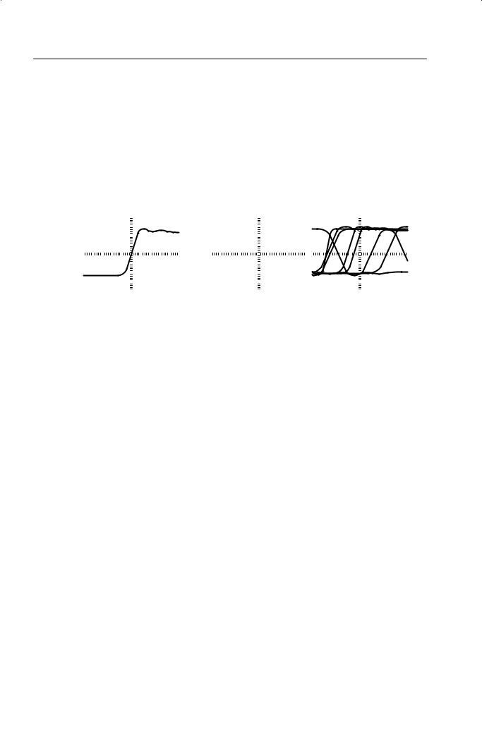
2.Check the shape of the displayed waveform.
Overcompensated
Undercompensated
Compensated correctly
3.If necessary, adjust your probe.
Repeat as necessary.
6 |
TDS 200-Series Digital Oscilloscope User Manual |

Getting Started
Self Calibration
The self calibration routine lets you quickly optimize the oscilloscope signal path for maximum measurement accuracy. You can run the routine at anytime but you should always run the routine if the ambient temperature changes by 5_ C or more.
To compensate the signal path, disconnect any probes or cables from the input connectors. Then, press the UTILITY button and select Do Self Cal to confirm that you are ready to proceed.
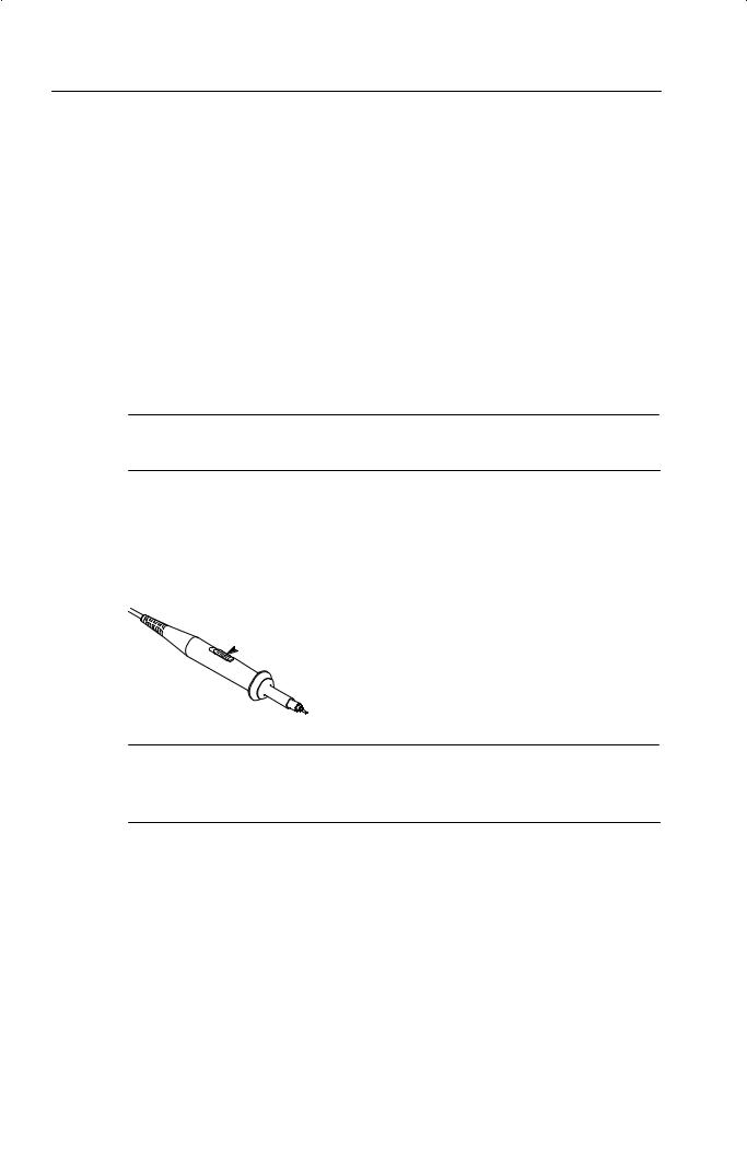
Probe Safety
A guard around the probe body provides a finger barrier for protection from electric shock.
Finger guard
WARNING. To avoid electric shock when using the probe, keep fingers behind the guard on the probe body.
To avoid electric shock while using the probe, do not touch metallic portions of the probe head while it is connected to a voltage source.
Connect the probe to the instrument and connect the ground terminal to ground before you take any measurements.
TDS 200-Series Digital Oscilloscope User Manual |
7 |
Getting Started
Probe Attenuation Setting
Probes are available with various attenuation factors which affect the vertical scale of the signal.
To change (or check) the probe attenuation setting, press the VERTICAL MENU button (of the channel you are using), and then press the menu selection next to Probe until the correct setting is displayed.
This setting remains in effect until changed again.
NOTE. The default Probe menu attenuation setting is 10X when the oscilloscope is shipped.
Be sure that the Attenuation switch on the P2100 probe is set to match the Probe menu selection in the oscilloscope. The probe switch settings are 1X and 10X.
 Attenuation switch
NOTE. When the Attenuation switch is set to 1X, the P2100 probe limits the bandwidth of the oscilloscope to 7 MHz. To use the full bandwidth of the oscilloscope, be sure to set the switch to 10X.
8 |
TDS 200-Series Digital Oscilloscope User Manual |
Basic Concepts
To use your oscilloscope effectively, you must understand the following basic concepts:
HTriggering
HAcquiring data
HScaling and positioning waveforms
HMeasuring waveforms
HSetting Up the oscilloscope
The figure below shows a block diagram of the various functions of an oscilloscope and their relationship to each other.
Each |
Vertical: |
Acquire data: |
Waveform |
|
|
gain and |
mode and |
record: |
Display |
||
channel |
|||||
position |
time base |
2500 points |
|
||
|
|
Computer interface (TDS2CM)
Ext
Trigger
AC Line
TDS 200-Series Digital Oscilloscope User Manual |
9 |
Basic Concepts
Triggering
The trigger determines when the oscilloscope starts to acquire data and display a waveform. When a trigger is set up properly, it can convert unstable displays or blank screens into meaningful waveforms.
|
|
|
|
|
|
|
|
|
|
|
|
|
|
|
|
|
|
|
|
|
|
|
|
|
|
|
|
|
|
|
|
|
|
|
|
|
|
|
|
|
|
|
|
|
|
|
|
|
|
|
|
|
|
|
|
|
|
|
|
|
|
|
|
|
|
|
|
|
|
|
|
|
|
|
|
|
|
|
|
|
|
|
|
|
|
|
|
|
|
|
|
|
|
|
|
|
|
|
|
|
|
|
|
|
|
|
|
|
|
|
|
|
|
|
|
|
|
|
|
|
|
|
|
|
|
|
|
|
|
|
|
|
|
|
|
|
|
|
|
|
|
|
|
|
|
|
|
|
|
|
|
|
|
|
|
|
|
|
|
|
|
|
|
|
|
|
|
|
|
|
|
|
|
|
|
|
|
|
|
|
|
|
|
|
|
|
|
|
|
|
|
|
|
|
|
|
|
|
|
|
|
|
|
|
|
|
|
|
|
|
|
|
|
|
|
|
|
|
|
|
|
|
|
|
|
|
|
|
|
|
|
|
|
|
|
|
|
|
|
|
|
|
|
|
|
|
|
|
|
|
|
|
|
|
|
|
Triggered waveform |
|
|
|
|
|
Untriggered waveforms |
||||||||||||||||||||||||
When the oscilloscope starts to acquire a waveform, it collects enough data so that it can draw the waveform to the left of the trigger point. The oscilloscope continues to acquire data while waiting for the trigger condition to occur. After it detects a trigger, the oscilloscope continues to acquire enough data so that it can draw the waveform to the right of the trigger point.
Source
You can derive your trigger from various sources: Input channels, AC Line, and External.
Input. The most commonly used trigger source is any one of the input channels. The channel you select as a trigger source will function whether it is displayed or not.
10 |
TDS 200-Series Digital Oscilloscope User Manual |

Basic Concepts
AC Line. You can use this trigger source when you want to look at signals related to the power line frequency, such as lighting equipment and power supply devices. The oscilloscope generates the trigger, so you do not have to input a trigger signal.
External (TDS 210 and TDS 220 Only). You can use this trigger source when you want to acquire data on two channels and trigger from a third. For example, you might want to trigger from an external clock or with a signal from another part of the test circuit.
The EXT and EXT/5 trigger sources both use the external trigger signal connected to the EXT TRIG connector. EXT uses the signal directly; you can use EXT on signals with a trigger level range of +1.6 V to – 1.6 V.
The EXT/5 trigger source divides the signal by 5 which extends the trigger level range from + 8 V to – 8 V. This allows the oscilloscope to trigger on a larger signal.
Types
The oscilloscope provides two types of triggers: Edge and Video.
Edge. You can use the edge trigger with analog and digital test circuits. An edge trigger occurs when the trigger input passes through a specified voltage level in the specified direction.
Video. You can use the video trigger on fields or lines of standard video signals. Refer to Triggering on a Video Signal on page 53.
Modes
The trigger mode determines how the oscilloscope behaves in the absence of a trigger event. The oscilloscope provides three trigger modes: Auto, Normal, and Single.
TDS 200-Series Digital Oscilloscope User Manual |
11 |

Basic Concepts
Auto. This trigger mode allows the oscilloscope to acquire a waveform even when it does not detect a trigger condition. If no trigger condition occurs while the oscilloscope waits for a specific period (as determined by the time-base setting), it will force itself to trigger.
Refer to Time Base on page 16 for more information on time bases.
When forcing invalid triggers, the oscilloscope cannot synchronize the waveform, and the waveform seems to roll across the display. If valid triggers occur, the display becomes stable on the screen.
You can use Auto mode to monitor an amplitude level, such as a power supply output, which may cause the waveform to roll across the display.
Normal. The Normal mode allows the oscilloscope to acquire a waveform only when it is triggered. If no trigger occurs, the oscilloscope will not acquire a new waveform, and the previous waveform, if any, will remain on the display.
Single. The Single mode allows the oscilloscope to acquire one waveform each time you press the RUN button, and the trigger condition is detected.
The data that the oscilloscope acquires depends on the acquisition mode. Refer to Acquisition Modes on page 15 for more information on the type of data each acquisition mode will acquire.
NOTE. When you use the Single trigger mode with the Average acquisition mode, the number of waveforms specified in the number of averages are acquired before the acquisition stops.
12 |
TDS 200-Series Digital Oscilloscope User Manual |
Basic Concepts
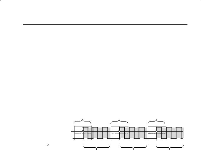
Holdoff
Triggers are not recognized during holdoff time (the period that follows each acquisition). For some signals, you need to adjust the holdoff period to produce a stable display.
The trigger signal can be a complex waveform with many possible trigger points on it, such as a digital pulse train. Even though the waveform is repetitive, a simple trigger might result in a series of patterns on the screen instead of the same pattern each time.
Acquisition |
Acquisition |
Acquisition |
interval |
interval |
interval |
Trigger level |
Holdoff |
|
Indicates |
|
|
trigger points |
|
|
Holdoff |
Holdoff |
Holdoff |
Triggers are not recognized during holdoff time.
For example, you could use the holdoff period to prevent triggering on any other pulse except the first one in a pulse train. This way, the oscilloscope would always display the first pulse.
To access the Holdoff control, press the HORIZONTAL Menu button, select Holdoff, and use the HOLDOFF knob to change the amount of time in the holdoff period.
TDS 200-Series Digital Oscilloscope User Manual |
13 |

Basic Concepts
Coupling
Trigger coupling determines what part of the signal passes on to the trigger circuit. Coupling types include DC, AC, Noise Rejection, High Frequency Rejection, and Low Frequency Rejection.
DC. DC coupling passes both AC and DC components.
AC. AC coupling blocks DC components.
Noise Rejection. Noise Reject coupling lowers the trigger sensitivity and requires more signal amplitude for stable triggering. This reduces the chance of falsely triggering on noise.
High Frequency Rejection. HF Reject coupling blocks the high frequency portion and passes on only the low frequency components.
Low Frequency Rejection. LF Reject coupling does the opposite of high frequency rejection.
Position
The horizontal position control establishes the time between the trigger and the screen center. Refer to Horizontal Scale and Position; Pretrigger Information on page 17 for more information on how to use this control to position the trigger.
Slope and Level
The Slope and Level controls help to define the trigger.
The Slope control determines whether the oscilloscope finds the trigger point on the rising or the falling edge of a signal. To access the trigger slope control, press the TRIGGER Menu button, select Edge, and use the Slope button to select Rising or Falling.
14 |
TDS 200-Series Digital Oscilloscope User Manual |

Basic Concepts
The Level control determines where on the edge the trigger point occurs. To access the trigger level control, press the HORIZONTAL Menu button, select Level, and use the LEVEL knob to change the value.
Positive-going |
|
Negative-going |
edge |
|
edge |
|
|
|
|
|
|
Trigger level can be adjusted vertically
Trigger slope can be positive or negative
Acquiring Data
When you acquire analog data, the oscilloscope converts it into a digital form. You can acquire data using three different acquisition modes. The timebase setting affects how rapidly data is acquired.
Acquisition Modes
There are three acquisition modes: Sample, Peak Detect, and
Average.
Sample. In this acquisition mode, the oscilloscope samples the signal in evenly spaced intervals to construct the waveform. This mode accurately represents analog signals most of the time.
TDS 200-Series Digital Oscilloscope User Manual |
15 |

Basic Concepts
However, this mode does not acquire rapid variations in the analog signal that may occur between samples. This can result in aliasing (described on page 18) and may cause narrow pulses to be missed. In these cases, you should use the Peak Detect mode to acquire data.
Peak Detect. In this acquisition mode, the oscilloscope finds the highest and lowest values of the input signal over a sample interval and uses these values to display the waveform. In this way, the oscilloscope can acquire and display narrow pulses, which may have otherwise been missed in Sample mode. Noise will appear to be higher in this mode.
Average. In this acquisition mode, the oscilloscope acquires several waveforms, averages them, and displays the resulting waveform. You can use this mode to reduce random noise.
Time Base
The oscilloscope digitizes waveforms by acquiring the value of an input signal at discrete points. The time base allows you to control how often the values are digitized.
To adjust the time base to a horizontal scale that suits your purpose, use the SEC/DIV knob.
Scaling and Positioning Waveforms
You can change the display of waveforms by adjusting their scale and position. When you change the scale, the waveform display will increase or decrease in size. When you change the position, the waveform will move up, down, right, or left.
16 |
TDS 200-Series Digital Oscilloscope User Manual |

Basic Concepts
The channel reference indicator (located on the left of the graticule) identifies each waveform on the display. The indicator points to the ground level of the waveform record.
Vertical Scale and Position
You can change the vertical position of waveforms by moving them up or down on the display. To compare data, you can align a waveform above another or you can align waveforms on top of each other.
You can change the vertical scale of a waveform. The waveform display will contract or expand about the ground level.
Horizontal Scale and Position; Pretrigger Information
You can adjust the Horizontal Position control to view waveform data before the trigger, after the trigger, or some of each. When you change the horizontal position of a waveform, you are actually changing the time between the trigger and the center of the display. (This appears to move the waveform to the right or left on the display.)
For example, if you want to find the cause of a glitch in your test circuit, you might trigger on the glitch and make the pretrigger period large enough to capture data before the glitch. You can then analyze the pretrigger data and perhaps find the cause of the glitch.
You change the horizontal scale of all the waveforms by using the SEC/DIV knob. For example, you might want to see just one cycle of a waveform to measure the overshoot on its rising edge.
TDS 200-Series Digital Oscilloscope User Manual |
17 |
Basic Concepts
The oscilloscope shows the time per division in the scale readout. Since all active waveforms use the same time base, the oscilloscope only displays one value for all the active channels, except when you use a Window Zone.
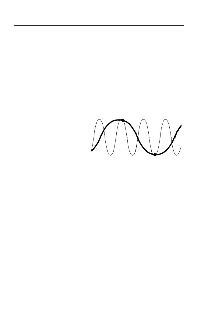
Aliasing. Aliasing occurs when the oscilloscope does not sample the signal fast enough to construct an accurate waveform record. When aliasing happens, you see a waveform with a frequency lower than the actual waveform being input or a waveform that is not stable even though the oscilloscope triggered.
Actual high-frequency 
 waveform
Apparent low-frequency 
 waveform due to aliasing
Sampled points 

One way to check for aliasing is to slowly change the horizontal scale with the SEC/DIV knob. If the shape of the waveform changes drastically, you may have aliasing.
To represent a signal accurately and avoid aliasing, you must sample the signal more than twice as fast as the highest frequency component. For example, a signal with frequency components of 5 MHz would need to be sampled at 10 Megasamples per second or faster.
18 |
TDS 200-Series Digital Oscilloscope User Manual |
 Loading...