


P H A S E R S H A R E® N E T W O R K I N G
M A N U A L


 ®
®
www.tek.com/Color_Printers/

PhaserShare® Networking Manual
V3 April 1999
071-0180-01

Copyright © Tektronix, Inc.
Unpublished rights reserved under the copyright laws of the United States. Contents of this publication may not be reproduced in any form without permission of Tektronix, Inc.
Tektronix®, Phaser®, PhaserShare®, the TekColor logo, ColorStix®, ColorCoat®, and Made For Each Other® are registered trademarks of Tektronix, Inc. Finepoint™, PhaserLink™, PhaserPrint™, the TekColor name, and PhaserSym™ are trademarks of Tektronix, Inc.
Adobe® and PostScript® are trademarks of Adobe Systems Incorporated which may be registered in certain jurisdictions.
Apple®, AppleTalk®, LocalTalk®, EtherTalk®, TokenTalk®, and Macintosh® are registered trademarks of Apple Computer, Inc.
SGI™ is a trademark of Silicon Graphics, Inc.
SPARC® is a registered trademark of SPARC International, Incorporated. SPARCstation™ is a trademark of SPARC International, Inc., licensed exclusively to Sun Microsystems, Inc.
Tektronix Phaser 840, Phaser 740, Phaser 780, and Phaser 360 printers are certified as NetWare print server devices, on both 3.12 and 4.1x NetWare systems. Bindery mode is also certified to comply on both 3.12 and 4.1x NetWare systems. NetWare NDS is certified on 4.1x NetWare systems.
Novell® and NetWare® are registered trademarks of Novell, Inc.
UNIX® is a registered trademark in the United States and other countries, licensed exclusively through X/Open Company, Ltd.
Times™, Helvetica™ and Palatino™ are trademarks of Linotype-Hell AG and/or its subsidiaries.
Other marks are trademarks or registered trademarks of the companies with which they are associated.
PANTONE®* Colors generated by Phaser Color Printers are fourand/or three-color process simulations and may not match PANTONE-identified solid color standards. Use current PANTONE Color Reference Manuals
for accurate colors.
PANTONE Color simulations are only obtainable on these products when driven by qualified Pantone-licensed software packages. Contact Pantone, Inc. for a current list of qualified licensees.
* Pantone, Inc.’s check-standard trademark for color reproduction and color reproduction materials. © Pantone, Inc., 1988.
Contents
1 |
Network Printing with Tektronix Color Printers |
||
|
Key components for networking Tektronix color printers 1 |
||
|
Network installation overview |
6 |
|
|
The printer’s Configuration Page |
6 |
|
|
How to tell which protocols are enabled |
8 |
|
|
The printer’s networking software |
8 |
|
|
Support for DOS systems 10 |
|
|
|
Tektronix PhaserPrint for UNIX software |
10 |
|
2 |
PhaserShare Series B Network Interfaces |
|
|
PhaserShare Series B Ethernet interface |
11 |
|
PhaserShare Series B Token Ring card |
14 |
|
PhaserShare Series B LocalTalk card 22 |
|
3 |
EtherTalk, LocalTalk, and TokenTalk Configuration |
|
|
Before you begin |
25 |
|
Configuration overview 25 |
|
|
Finding the printer’s name in the Chooser 26 |
|
|
Changing the printer’s name (optional) 27 |
|
|
Changing the printer’s EtherTalk/TokenTalk zone (optional) 29 |
|
|
Troubleshooting |
30 |
4 |
Novell NetWare Configuration |
|
|
The printer’s NetWare interface 31 |
|
|
Before beginning the configuration procedure |
32 |
|
Configuration software for NetWare 33 |
|
|
NetWare configuration for Windows environments 33 |
|
|
Troubleshooting Windows configurations 36 |
|
|
Setting IPX frame types from the front panel |
40 |
5 |
PhaserShare Administrator Software for NetWare Networks |
|
Introduction to the PhaserShare Administrator 43 |
|
NetWare configuration with the PhaserShare Administrator 44 |
|
Installation 44 |
|
Using the PhaserShare Administrator 46 |
|
PhaserShare Administrator on-line help 50 |
6 |
TCP/IP Configuration Overview |
|
|
|
Before you begin 52 |
|
|
|
Extracting files from unix.tar 52 |
|
|
|
Printing the Configuration Page |
52 |
|
|
TCP/IP configuration overview |
53 |
|
|
|
PhaserShare Networking Manual |
iii |
7 |
TCP/IP Printer Configuration (All Platforms) |
|
|
|
|
Setting the printer’s IP addressing parameters 55 |
|
|
|
|
General information on setting IP parameters (front panel) 57 |
|
||
|
Setting IP parameters: Phaser 840 printer front panel |
57 |
|
|
|
Setting IP parameters: Phaser 740 printer front panel |
58 |
|
|
|
Setting IP parameters: Phaser 780 printer front panel |
60 |
|
|
|
Setting IP parameters: Phaser 360 printer front panel |
63 |
|
|
|
Setting IP parameters: RARP or BOOTP 65 |
|
|
|
|
Setting IP parameters: DHCP 66 |
|
|
|
|
Supported BOOTP/DHCP fields 68 |
|
|
|
|
Enabling and disabling RARP and BOOTP/DHCP (front panel) |
69 |
||
|
Setting IP parameters: PhaserLink Printer Management Software |
73 |
||
|
Controlling host access |
76 |
|
|
|
Receiving printer status |
79 |
|
|
8 |
TCP/IP Host Configuration (UNIX) |
|
|
|||
|
Configuring a host |
83 |
|
|
|
|
|
Troubleshooting |
94 |
|
|
|
|
9 |
TCP/IP Configuration (OS/2 Warp/LAN Server) |
|||||
|
Setting the printer’s IP addressing parameters 95 |
|||||
|
Creating an LPR queue in OS/2 Warp Connect (direct LPR connection to the printer) 96 |
|||||
|
OS/2 client-to-server setup |
97 |
|
|
|
|
|
Warp Server 4.0/Warp Connect |
98 |
|
|||
10 |
Windows NT |
|
|
|
|
|
|
Setting the printer’s IP address |
99 |
|
|
||
|
Adding the Windows NT 4.0 driver on a Windows NT 4.0 server or workstation 99 |
|||||
|
Adding the Windows NT 4.0 driver on a |
|
||||
|
Windows NT 3.51 server 104 |
|
|
|
||
|
Adding a Windows NT 3.x driver |
109 |
|
|||
|
Windows NT network communication |
112 |
||||
|
Windows NT network troubleshooting |
113 |
||||
11 |
Windows 95 and Windows 98: PhaserPort Software |
|||||
|
TCP/IP configuration for the PC |
117 |
|
|||
|
Setting the printer’s IP address |
117 |
|
|||
|
PhaserPort software installation |
118 |
|
|||
|
Adding a port for a new printer |
119 |
|
|||
|
Adding a port to an existing printer |
119 |
||||
|
Changing a port’s IP address |
120 |
|
|
||
iv |
PhaserShare Networking Manual |
12 |
PhaserLink Printer Management Software |
||
|
System requirements |
121 |
|
|
Multiple language support |
121 |
|
|
Accessing printer information from a browser 122 |
||
|
Printer information pages |
122 |
|
|
Printer status display |
124 |
|
|
PhaserLink Printer Management Software help files 125 |
||
|
Setting printer parameters: PhaserLink Printer Management Software pages 126 |
||
|
Information Forwarding 126 |
||
13 |
Printer Management |
|
|
|
|
|
Job accounting |
127 |
|
|
|
|
PhaserLink PDF Direct Printing 128 |
|
|
||
|
Phaser 840 Intelligent Ready |
129 |
|
|
|
|
PhaserLink Status Notification (Email Notification) |
130 |
|
||
|
Usage Profile reports (Phaser 840, 740 and 780 printers only) |
131 |
|||
|
Printing Usage Profile reports from the front panel |
132 |
|
||
|
Printing verbose Usage Profile reports from the front panel |
133 |
|||
|
Printing Usage Profile reports from PhaserLink Printer Management Software 134 |
||||
|
Sending Usage Profile reports via email from the front panel |
134 |
|||
|
Sending Usage Profile reports via email: PhaserLink Printer Management Software 136 |
||||
|
Controlling Usage Profile email reporting 137 |
|
|
||
|
Email to Tektronix 138 |
|
|
|
|
|
Reading Usage Profile reports |
139 |
|
|
|
|
Report fields |
140 |
|
|
|
|
Logs 145 |
|
|
|
|
14 |
Getting Help |
|
|
If you need help from Tektronix |
153 |
|
Using the automated fax systems |
155 |
|
Receiving email update notices |
156 |
15 Disabling Protocols
Disabling protocols: front panel 158 If the front panel is locked 165
Disabling protocols: PhaserShare Administrator 166
Disabling protocols: PhaserLink Printer Management Software 166
PhaserShare Networking Manual |
v |
16 Resetting the Printer
Resetting the printer: PhaserLink Printer Management Software 167 Resetting your printer using the Apple Printer Utility 168
17FTP Interface
Index
vi |
PhaserShare Networking Manual |
Chapter
1 Network Printing with Tektronix Color Printers
This manual provides information for system administrators and others who need to install Tektronix Phaser 840, Phaser 740, Phaser 780, and Phaser 360 printers equipped with PhaserShare Series B network interfaces.
■Before using this manual, unpack and set up your printer. Install the appropriate drivers on any PC and Macintosh computers on your network. Instructions for unpacking, set-up, and installation are contained in your printer’s user documentation.
■After your printer is set up, use this manual in conjunction with your printer’s PhaserShare Administrator or PhaserLink Printer Management Software to configure the printer on the network.
This manual covers the following hardware and software versions:
■PhaserShare Series B interfaces
■PhaserShare Administrator version 3.9
Key components for networking Tektronix color printers
The following items are key components for networking your Tektronix printer:
■PhaserShare Series B network interface. This brings ease-of-use, superb shareability and broad compatibility to Tektronix Phaser color printers. For more information, see “PhaserShare Series B network interface” on page 2.
■PhaserShare Administrator software. PhaserShare Administrator software makes it easy to install, configure, and manage Phaser printers on a NetWare network. For more information, see Chapter 5, “PhaserShare Administrator Software for NetWare Networks”.
■PhaserLink Printer Management Software. PhaserLink Printer Management Software is internal printer software that provides printer status and supports printer management through a World Wide Web browser. For more information, see Chapter 12, “PhaserLink Printer Management Software”.
■PhaserPrint for UNIX software. PhaserPrint for UNIX software provides a driver with push-button control of printer features and fast raster file printing capability from UNIX workstations. For more information, see “Tektronix PhaserPrint for UNIX software” on page 10.
PhaserShare Networking Manual |
1 |
1 Network Printing with Tektronix Color Printers
PhaserShare Series B network interface
The Phaser 840, 740, 780, and 360 printers support the PhaserShare Series B network interface. These printers are equipped with a built-in PhaserShare Series B network interface with a 10BaseT Ethernet connector. This printer can be equipped with these optional PhaserShare Series B network cards:
■PhaserShare Series B Fast Ethernet card. This card is equipped with a combined 10BaseT and 100BaseTx connector and a 10Base2 (BNC) connector. The combined 10BaseT/100BaseTx connector can be connected to either a 10BaseT or 100BaseTx network, and it will automatically adjust to the correct data rate using a process called auto-negotiation. If no connection is made to the 10BaseT/100BaseTx connector, the card is prepared to communicate using the 10Base2 connector.
■PhaserShare Series B Token Ring card. This card is equipped with STP (Shielded Twisted Pair) and UTP (Unshielded Twisted Pair) connectors. Only one connector at a time can be used.
■PhaserShare Series B LocalTalk card (AppleTalk).
PhaserShare network cards can be purchased initially with the printer as options or added later as upgrade kits. A printer can have only one card at a time installed. When a PhaserShare Series B Fast Ethernet or Token Ring card is installed, the standard 10BaseT connector on the printer’s rear panel is disabled. The card and the printer’s standard parallel port can be simultaneously active. All network protocols can be simultaneously active.
PhaserShare cards
PhaserShare cards work with the following printers: Phaser 380, 350, 340, 560, 550, 540, and 600. PhaserShare cards enable you to use your printer with Ethernet, Token Ring, LocalTalk, or serial connections. PhaserShare cards can be purchased initially with the printer as options or added later as upgrade kits.
A printer can have only one PhaserShare card installed at a time. When a PhaserShare card is installed, all ports on the card and the printer’s standard parallel port can be simultaneously active. Also, all network protocols can be simultaneously active.
For information on networking printers with PhaserShare cards, refer to the
PhaserShare Networking System Administrator Manual, part number 070-9789-00.
2 |
PhaserShare Networking Manual |
Network Printing with Tektronix Color Printers 1
Recognizing PhaserShare Series B interfaces and earlier PhaserShare cards
On your network, you may have some Tektronix printers equipped with PhaserShare Series B interfaces and other Tektronix printers equipped with earlier PhaserShare cards. Printers equipped with earlier PhaserShare cards are supported differently in printer management software such as the PhaserShare Administrator and PhaserLink Printer Management Software. There are several ways to determine if the printer is equipped with a PhaserShare Series B interface or an earlier PhaserShare card:
■Printer model. PhaserShare Series B cards work with Phaser 840, 740, 780, and 360 printers. PhaserShare cards work with the following printers: Phaser 380, 350, 340, 560, 550, 540, and 600.
■Card rear panel. The cards are labeled on the rear panel.
■The printer’s Configuration Page. For Series B interfaces, Series B appears following the Network Information area on the printer’s Configuration Page. If an earlier PhaserShare card is installed, the printer’s Configuration Page reports the type of card installed in the PhaserShare field.
■The printer’s Startup Page. For Series B interfaces, Series B appears in the Ethernet, Token Ring, or LocalTalk fields on the printer’s Startup Page. If a PhaserShare card is installed, the printer’s Startup Page reports the available connections in the Ports field.
■PhaserLink Printer Management Software. If the Adobe PostScript field reads Adobe PostScript Level 3 Version, the interface is Series B. If the field reads Adobe PostScript Level 2 Version, the printer supports PhaserShare network cards (not Series B). The Adobe PostScript field is on the View Printer Information page or on the View and Configure General Settings page, depending on the printer type. Links to these pages can be accessed by clicking the Configuration link. For more information on PhaserLink Printer Management Software, see Chapter 12, “PhaserLink Printer Management Software”.
■PhaserShare Administrator. In the PhaserShare Administrator, Series B interfaces are identified in the Ethernet or Token Ring tabs, where Series B is displayed in the Interface Information area. For more information on the PhaserShare Administrator, see Chapter 5, “PhaserShare Administrator Software for NetWare Networks”.
PhaserShare Networking Manual |
3 |
1 Network Printing with Tektronix Color Printers
Environments supported
Tektronix Phaser printers are compatible with mixed PC, Macintosh, and UNIX environments. The printer automatically switches between the printer’s ports and network protocols to service all computers on the network.
Phaser printers are compatible with nearly all PC client/server environments. The printer’s Ethernet and Token Ring network interfaces are compatible with the following:
■NetWare servers via the IPX (Internet Packet Exchange) protocol
■Windows NT servers over TCP/IP or EtherTalk protocols
■LANServer 4.0 servers via TCP/IP
■UNIX workstation via TCP/IP
■Macintosh computers via AppleTalk (LocalTalk, EtherTalk and TokenTalk).
■Windows 98
■Windows 95
Supported PC platforms
Any PC in the server environments listed in the previous topic, “Environments supported,” can print over the network to a Phaser printer, including the following:
■Windows 98
■Windows 95
■Windows 3.1
■Windows NT
■Windows for Workgroups
■OS/2 Warp
■DOS
4 |
PhaserShare Networking Manual |

Network Printing with Tektronix Color Printers 1
Phaser printers are compatible with Banyan Vines and Microsoft LAN Manager servers; however, third-party interfaces are required. Contact Tektronix Technical Support for more information (see Chapter 14, “Getting Help”).
Workstations |
|
|
|
|
Clients |
|
|
|
|
Windows 95 |
|
UNIX |
|
|
|
|
|
|
|
|
|
Windows 3.1 |
|
Macintosh |
|
|
|
|
|
|
|
|
|
Windows NT |
|
Windows 95 |
|
|
|
|
|
|
|
|
|
Windows for Workgroups |
|
(peer - to - peer) |
|
|
|
|
|
|
|
|
|
OS/2 Warp |
|
|
|
|
|
|
|
|
|
|
|
|
DOS |
|
|
|
|
|
|
|
|
|
|
|
|
|
|
|
|
|
|
|
|
|
|
|
|
Server
Novell NetWare (IPX)
Windows NT (EtherTalk
or TCP/IP)
LAN Server 4.0 (TCIP/IP)
UNIX (TCP/IP)
Phaser Color Printer
With PhaserShare Ethernet or Token Ring interface
9538-04c
PhaserShare Networking Manual |
5 |

1 Network Printing with Tektronix Color Printers
Network installation overview
Step 1 |
Unpack and set up |
This step must be done before attempting to configure the printer on a network. |
|
the printer. |
Printer setup includes installing ink or toner, loading paper trays, and turning on |
|
|
the printer. See your printer’s user documentation for information about printer |
|
|
setup. |
|
|
|
Step 2 |
Install the network |
This step is necessary if the printer is to be equipped with an optional network |
|
card in the printer. |
card. It is not necessary when using the printer’s built-in Ethernet connector. |
|
|
This step is done at the factory when a network card is purchased initially with |
|
|
your printer. |
|
|
When a network card is purchased later as an upgrade kit, follow the |
|
|
installation instructions included with the card. |
|
|
Information on physically connecting the printer to networks is provided in this |
|
|
manual: |
|
|
For Ethernet, see “PhaserShare Series B Ethernet interface” on page 11. |
|
|
For Token Ring, see “PhaserShare Series B Token Ring card” on page 14. |
|
|
For LocalTalk, see “PhaserShare Series B LocalTalk card” on page 22. |
|
|
|
Step 3 |
Network |
For LocalTalk, EtherTalk, or TokenTalk, see Chapter 3, “EtherTalk, LocalTalk, |
|
configuration. |
and TokenTalk Configuration”. |
|
|
For NetWare, see Chapter 4, “Novell NetWare Configuration”. |
|
|
For TCP/IP, see: |
|
|
Chapter 6, “TCP/IP Configuration Overview”. |
|
|
Chapter 7, “TCP/IP Printer Configuration (All Platforms)”. |
|
|
Chapter 8, “TCP/IP Host Configuration (UNIX)”. |
|
|
Chapter 9, “TCP/IP Configuration (OS/2 Warp/LAN Server)” |
|
|
Chapter 11, “Windows 95 and Windows 98: PhaserPort Software”. |
|
|
For Windows NT, see Chapter 10, “Windows NT”. |
|
|
|
The printer’s Configuration Page
Your printer can generate a Configuration Page that lists the following information:
■General printer information, including TekColor settings
■Communication and network parameters for all ports
■SCSI disk settings (if the printer has a SCSI port)
The information supplied on the Configuration Page is helpful when you are installing and configuring the printer on a network. There are two ways to print the Configuration Page:
■Use the printer’s front panel. You can easily print the Configuration Page from the printer’s front panel. Use this method if your printer is not yet configured on the network. Refer to:
■“Printing a Configuration Page: Phaser 840 front panel” on page 7.
■“Printing a Configuration Page: Phaser 740 and 360 front panels” on page 7.
■“Printing a Configuration Page: Phaser 780 front panel” on page 7.
■Use PhaserLink Printer Management Software. With a TCP/IP connection and a World Wide Web browser, you can use PhaserLink Printer Management Software; see “Printing a Configuration Page: PhaserLink Printer Management Software” on page 7.
6 |
PhaserShare Networking Manual |
Network Printing with Tektronix Color Printers 1
Printing a Configuration Page: Phaser 840 front panel
1.When the front panel displays READY TO PRINT, press the down-arrow button until Menu is highlighted. Press Select.
2.Press the down-arrow button until Printer Configuration is highlighted. Press Select.
3.Press the down-arrow button until Print Configuration Page is highlighted. Press Select.
Printing a Configuration Page: Phaser 740 and 360 front panels
1.While Ready is displayed, press Menu; the printer displays the first item in the menu:
Help Pages
<---- |
----> |
Menu |
2.Press Menu to access the Help Pages; the following message appears:
Menu Map
<---- |
----> |
3.Press <---- or ----> until the following message appears:
Configuration Page
<---- |
----> |
4.Press Print.
Printing a Configuration Page: Phaser 780 front panel
1.While Ready is displayed, press Select; the Printer menu is displayed:
Printer Menu |
|
Help Pages |
Menu |
2.Press Menu; the Help Pages menu is displayed:
Help Pages |
|
Configuration Page |
3.Press Print.
Printing a Configuration Page: PhaserLink Printer Management Software
1.From the printer’s home page, click Configuration; this displays the View and Configure Settings page.
2.On the View and Configure Settings page, select Configuration Page from the pull-down list. Click Print.
For more information on PhaserLink Printer Management Software, see Chapter 12, “PhaserLink Printer Management Software”.
PhaserShare Networking Manual |
7 |
1 Network Printing with Tektronix Color Printers
How to tell which protocols are enabled
All protocols can be enabled and disabled. The Configuration Page reports which protocols are enabled. If a protocol is enabled, the field for that protocol lists the current parameters. If the protocol is disabled, the field for that protocol contains an entry reading Disabled.
The printer’s networking software
The printer is shipped with a software CD-ROM, which contains software that you may need to install your printer on a network. The CD-ROM also contains on-line documentation, printer drivers, and other printer software. A single integrated installer is used to install printer drivers and other software.
Obtaining networking software for Phaser 840, 740, and 780 printers
You obtain the networking software from the CD-ROM by running the installer:
1.Insert the printer’s software CD-ROM into the CD-ROM drive.
■If the Windows autorun feature is enabled, the CD-ROM launches automatically.
■If the Windows autorun feature is disabled, double-click My Computer, then double click the CD icon to launch the CD-ROM.
2.View the brief introductory information, then click Install Drivers to launch the installer.
3.When you are prompted to select Easy Install or Custom Install, select
Custom Install.
4.In the Custom Install dialog box, check the box for Network Utilities.
5.If you are running the installer on a computer that has NetWare software installed, you can also check the boxes to install the PhaserShare Administrator software. For more information on the PhaserShare Administrator software, see Chapter 5, “PhaserShare Administrator Software for NetWare Networks”.
6.To complete the installation, follow the on-screen prompts.
8 |
PhaserShare Networking Manual |

Network Printing with Tektronix Color Printers 1
Obtaining networking software for Phaser 360 printers
You obtain the networking software from the CD-ROM by running the installer:
1.Locate and run the installer on the printer’s CD-ROM. On a PC, the file is
SETUP.EXE; on a Macintosh, it is Phaser 360 Installer.
2.When you are prompted to select Easy Install or Custom Install, select Custom Install.
3.In the Custom Install dialog box, check the box for Network Utilities.
4.If you are running the installer on a computer that has NetWare software installed, you can also check the boxes to install the PhaserShare Administrator software. For more information on the PhaserShare Administrator software, see Chapter 5, “PhaserShare Administrator Software for NetWare Networks”.
5.To complete the installation, follow the on-screen prompts.
Network administration software
|
The following table lists the network administration software according to |
|
environment (network protocol, platform, and printer). |
Network administration software |
|
|
|
Environment |
Software |
|
|
NetWare; Windows 95, |
Network queue configuration: PhaserShare Administrator (Novell PCONSOLE |
Windows NT, and |
and NWAdmin can also be used.) |
Windows 3.1 |
Printer configuration: PhaserShare Administrator (Over TCP/IP, PhaserLink |
|
|
|
Printer Management Software can also be used; Novell’s PCONSOLE and |
|
NWAdmin cannot configure the PhaserShare network interface.) |
|
Printer status monitoring: Windows Print Monitor (over TCP/IP, PhaserLink |
|
Printer Management Software can also be used; PhaserLink Printer Management |
|
Software provides status on additional Tektronix printer features.) |
|
|
TCP/IP; Windows 95 and |
Printer configuration: PhaserLink Printer Management Software |
Windows 3.1 |
Printer status monitoring: PhaserLink Printer Management Software |
|
|
|
|
TCP/IP; Windows NT |
Printer configuration: PhaserLink Printer Management Software (PhaserLink |
|
Printer Management Software does not set up queues on the print server.) |
|
Printer status monitoring: PhaserLink Printer Management Software |
|
|
AppleTalk; Macintosh 7.x |
Printer configuration: PhaserLink Printer Management Software (MacTCP or |
and 8.x |
Open Transport required) |
|
Printer status monitoring: PhaserLink Printer Management Software (MacTCP |
|
or Open Transport required) |
|
|
TCP/IP; UNIX |
Printer configuration: PhaserLink Printer Management Software (If using |
|
PhaserPrint for UNIX for printing, use PhaserPrint to set up print queues.) |
Printer status monitoring: PhaserLink Printer Management Software
PhaserShare Networking Manual |
9 |
1 Network Printing with Tektronix Color Printers
Support for DOS systems
For information on installing Tektronix printers in DOS environments, see the printer’s CD-ROM. They contain PostScript utility files that can be sent to the printer for network configuration in DOS environments. They also contain a DOS application, NWSET, for printer configuration on NetWare networks.
For information on how to use the DOS configuration files, see the README files on the printer’s CD-ROM. PC users will find the README file for the PostScript utility files in the UTILS directory; the README file for NWSET is in the NETWARE directory. (Macintosh users will find the ReadMe file for the PostScript utility files in the Network Utilities folder).
Tektronix PhaserPrint for UNIX software
For UNIX environments, Tektronix offers PhaserPrint software. PhaserPrint for UNIX provides fast raster screen copy printing to Tektronix color printers. PhaserPrint for UNIX also provides a graphical user interface for push-button control of Tektronix printer features.
PhaserPrint for UNIX is available for these workstations:
■Sun: SunOS 4.1.4, Solaris 2.3 and 2.4
■SGI: IRIX 5.2, 5.3, 6.2, 6.3, and 6.4
■HP 9000 700/800: HP-UX 9.0.5 and 10.2
■IBM RS/6000: AIX 3.2 and 4.2
■DECstation: ULTRIX 4.0 and 4.4
■ DEC Alpha AXP: OSF/1 3.0, 3.2, and Digital UNIX 4.0
PhaserPrint for UNIX works with the workstation’s native spooling system to print PostScript files and raster files in these formats: Sun Raster Format (SRF), xwd, SGI RGB, HP Starbase, TIFF, PBM, GIF, PCX, and BMP.
Your printer’s CD-ROM contains a demonstration copy of PhaserPrint for UNIX and an on-line instruction guide in the unix/unixdemo directory. You can also obtain a demonstration copy at this Tektronix site:
ftp.tek.com/cpid/UNIX/phaserprint2.1/demo
10 |
PhaserShare Networking Manual |
Chapter
2 PhaserShare Series B
Network Interfaces
PhaserShare Series B network cards work with the Phaser 840, 740, 780, and 360 printers. Printers that work with PhaserShare Series B network cards have a built-in PhaserShare Series B Ethernet interface on the rear panel. Earlier printers
(Phaser 380, 350, 340, 560, 550, 540, and 600) may be equipped with earlier PhaserShare network cards; these printers have no built-in network connections on the rear panel. If you are not sure which network interface your printer has, see “Recognizing PhaserShare Series B interfaces and earlier PhaserShare cards” on page 3.
This chapter provides information on connecting PhaserShare Series B interfaces to the network; for information on installing PhaserShare Series B network cards, see the instruction sheet that is shipped with each card.
PhaserShare Series B Ethernet interface
Ethernet is a communication standard that supports very high speed data transmission. Ethernet offers significant speed improvement compared to serial, parallel, and LocalTalk connections. Speed improvement varies greatly depending on network traffic, computer hardware, and other factors.
The PhaserShare Series B Ethernet interface conforms to the IEEE 802.3 and Ethernet II standards. With the printer’s built-in Ethernet interface, you can connect the printer directly to an Ethernet network using twisted pair (10BaseT) cables. With the PhaserShare Series B Ethernet card, you can connect the printer directly to an Ethernet network using twisted pair (10BaseT or 100BaseTx) or thin coax (10Base2) cables. Connecting the printer using thick coax (10Base5) requires an adapter; contact your dealer to obtain adapters, cables, and terminators.
When a PhaserShare Series B Ethernet card is installed, the built-in Ethernet connector is disabled; use the connectors on the card.
When a PhaserShare Series B card is purchased initially with the printer, it is installed at the factory. When a PhaserShare Series B card is purchased later as an upgrade kit, follow the instructions that are shipped with the card.
C A U T I O N
To avoid damaging the network interface, turn off the printer before making any
Ethernet connections.
PhaserShare Networking Manual |
11 |
2 PhaserShare Series B Network Interfaces
Ethernet connections and indicators
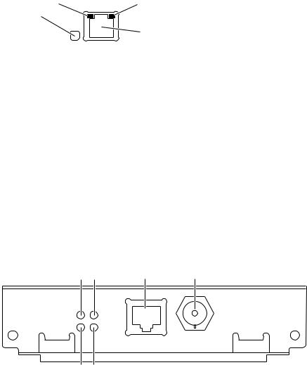
The printer’s built-in Ethernet connector
The printer’s built-in Ethernet connector has the following connections and indicators:
1.LINK indicator (Phaser 360 only); on indicates a working connection to a hub, off indicates no connection to a hub.
2.RCV indicator (green); blinks while the network interface is receiving.
3.XMT indicator (yellow); blinks while the network interface is transmitting.
4.Twisted pair (10BaseT) connector.
2 |
3 |
RCV |
XMT |
1
4
LNK Ethernet
0180-01
PhaserShare Series B Ethernet card
The PhaserShare Series B Ethernet card has the following connections and indicators:
1.TX indicator (yellow); blinks while the network interface is transmitting.
2.RX Link indicator (green); blinks while the network interface is receiving.
3.Speed indicator (yellow); on indicates 100 Mbps, off indicates 10 Mbps.
4.Twisted pair connection indicator; on indicates a working connection to a hub, off indicates no connection to a hub. If the 10Base2 connector (6) is used, this indicator is off.
5.Twisted pair (10BaseT or 100BaseTx) connector.
6.Thin coax (10Base2) connector.
1 |
3 |
5 |
6 |
PhaserShareTM
100
Series B TX Mbs
Ethernet Card
RX |
TP |
|
|
LINK |
10Base2 |
|
10/100Base-TX |
|
2 |
4 |
9789-05 |
12 |
PhaserShare Networking Manual |
PhaserShare Series B Network Interfaces 2
Ethernet cables and termination
N O T E
To fully comply with EMI specifications, the use of shielded or screened cables may be required. “Shielded” describes IBM-defined cables used with the DB-9 connector. “Screened” describes cables that are electrically similar to Category 4 UTP, but with an added shield or screen.
10BaseT or 100BaseTx (Twisted Pair)
100BaseTx requires Category 5 (100-Ohm UTP) cabling.
The Ethernet standard does not allow a direct 10BaseT connection between a single computer and a single printer. Use 10Base2 (Thin Ethernet) to connect a single computer to a single printer.
C A U T I O N
Do not use “silver satin” telephone extension cables for 10BaseT networks, either as drop cords or as patch cables in the wiring closet. (Silver satin cables are flat, usually silver or gray, with 28-gauge stranded or tinsel conductors.) Do not use shielded twisted pair cable intended for IBM Token Ring networks or voice-grade (level 1 or 2) unshielded twisted pair cable for wiring runs. These cables do not meet the requirements for 10BaseT and will lead to unreliable operation.
10Base2 (Thin Ethernet)
Depending on the type of Ethernet cables you use and your network configuration, you may need to use terminators at certain points in the installation. Refer to the manufacturer’s documentation for your Ethernet adapters and cables for details.
10Base5 (Thick Ethernet)
Connecting the printer using thick coax (10Base5) requires an adapter; contact your dealer to obtain adapters, cables, and terminators.
PhaserShare Networking Manual |
13 |
2 PhaserShare Series B Network Interfaces
PhaserShare Series B Token Ring card
The PhaserShare Series B Token Ring port conforms to the IEEE 802.5 standard. With the PhaserShare Series B Token Ring card, you can connect the printer directly to a Token Ring network using shielded twisted pair (STP; IBM Type 1) or unshielded twisted pair (UTP; IBM Type 3) cables. Contact your dealer to obtain adapters and cables.
N O T E
To fully comply with EMI specifications, the use of shielded or screened cables may be required. “Shielded” describes IBM-defined cables used with the DB-9 connector. “Screened” describes cables that are electrically similar to Category 4 UTP, but with an added shield or screen.
When a PhaserShare Series B card is purchased initially with the printer, it is installed at the factory. When a PhaserShare Series B card is purchased later as an upgrade kit, follow the installation instructions that are shipped with the card.
When a PhaserShare Series B Token Ring card is installed in the printer, the printer’s built-in Ethernet connector is disabled.
C A U T I O N
To avoid damaging the network interface, turn off the printer before making any
Token Ring connections.
Token Ring connections and indicators
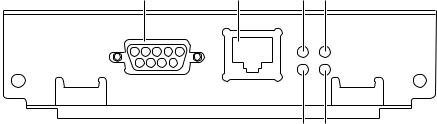
The PhaserShare Series B Token Ring card has the following connections and indicators on the rear panel:
1.Shielded Twisted Pair (STP; IBM Type 1) connector (DB-9).
N O T E
The STP port on the PhaserShare Token Ring card supports cable lengths up to 150 meters (492 feet) from the interface to the MAU (Medium Access Unit), including lobe and patch cables.
2.Unshielded Twisted Pair (UTP; IBM Type 3) connector (RJ-45).
3.Ring speed indicator (yellow); on indicates 16 Mbps, off indicates 4 Mbps.
4.TX indicator (yellow); blinks while the interface is transmitting.
5.Connection indicator (green); on indicates that the card is asserting its ring insertion control signal.
6.RX indicator (green); blinks while the interface is receiving.
1 |
2 |
3 |
4 |
|
PhaserShareTM |
|
16 |
|
|
Series B |
|
|
|
|
|
Mbs |
|
TX |
|
Token Ring Card |
|
|
||
|
INS |
|
RX |
|
STP |
|
|
||
|
UTP |
|
|
|
|
|
5 |
6 |
9789-06 |
14 |
PhaserShare Networking Manual |

PhaserShare Series B Network Interfaces 2
Ring speed jumper
The Token Ring card is equipped with a single three-pin jumper to set the ring speed. There are two settings: 4 Mbps and 16 Mbps.
N O T E
If you received your printer with the Token Ring card already installed, you must turn off the printer and remove the card before you change the jumper setting.
The following illustration shows a top view of the card and the location of the jumper.
1. |
Rear panel |
|
2. |
Jumper |
|
|
1 |
|
|
2 |
|
|
16 Mbps |
4 Mbps |
|
|
9789-03 |
PhaserShare Networking Manual |
15 |
2 PhaserShare Series B Network Interfaces
Token Ring configuration
You can set the Token Ring Frame Routing from the printer’s front panel. When you have the Frame Routing set, you may want to set other Token Ring parameters. See “How to configure Token Ring parameters:” on page 19. See the table “Token Ring parameters” on page 18 for a list of all settable Token Ring parameters.
Setting the Frame Routing from the Phaser 740 and 360 front panels
When the Token Ring card is installed in the printer, you can set the Frame Routing from the printer’s front panel. The choices are Transparent (no source routing) or Source Route (use source routing).
N O T E
If you are attempting to perform any front panel procedure and you don’t see the expected menu choices, the front panel may be locked. For information on how to unlock it, see “If the front panel is locked” on page 165.
1.Press Menu; the front panel displays Help Pages.
2.Press ----> or <---- until the front panel displays Network Settings.
3.Access the Frame Routing menu:
a.Press Menu until the front panel displays Token Ring.
b.Press Menu; the front panel displays the first of two Frame Routing choices.
4.Select the desired Frame Routing: Transparent or Source Route:
a.Press ----> until the Frame Routing choice you want is displayed.
b.Press OK to enter your choice into the printer; the front panel briefly displays Selected, then returns to the Token Ring display.
5.Return the printer to normal operation:
a.Press Exit until the front panel displays Network Settings.
b.Press Exit again.
■If you have changed any parameters that require a printer reset to take effect, you will be prompted to reset the printer. If you press Reset, the printer resets. If you press Resume, the front panel displays Network Settings. Press Exit; the printer returns to normal operation, but the changes you have made will not take effect until the next time the printer is reset.
■If you have not changed any parameters that require a printer reset to take effect, the front panel displays Ready.
16 |
PhaserShare Networking Manual |
PhaserShare Series B Network Interfaces 2
Setting Frame Routing from the Phaser 780 printer front panel
When the Token Ring card is installed in the printer, you can set the Frame Routing from the printer’s front panel. The choices are Transparent (no source routing) or Source Route (use source routing).
1.While Ready is displayed, press Select; the Printer menu is displayed:
Printer Menu |
|
Help Pages |
Menu |
2.Press the left or right arrow buttons until the front panel displays Network Settings.
Printer |
Menu |
|
Network |
Settings |
Menu |
3.Press Menu to enter the Network Settings menu; the front panel displays:
Network Settings |
|
Token Ring |
Menu |
4.Press Menu again; the front panel displays the first of two Frame Routing choices.
5.Select the desired Frame Routing: Transparent or Source Route:
a.Press the right arrow button until the Frame Routing choice you want is displayed.
b.Press Select to enter your choice into the printer; the front panel briefly displays Selected, then displays the selected Frame Routing choice again.
6.Return the printer to normal operation:
a.Press Exit (the far right button) until the front panel displays:
Network Settings |
|
Token Ring |
Menu |
b.Press Exit again.
■If you have changed any parameters that require a printer reset to take effect, you will be prompted to reset the printer. If you press Confirm, the printer resets. To return to normal operation without resetting the printer, press Exit (the far right button); Printer Menu appears on the top line of the display. Press Exit again; the printer returns to normal operation, but the changes you have made will not take effect until the next time the printer is reset.
■If you have not changed any parameters that require a printer reset, press Exit again; the front panel displays Ready.
PhaserShare Networking Manual |
17 |

2 PhaserShare Series B Network Interfaces
Token Ring parameters
Parameter |
Description |
Choices |
Network Address Token Ring Address (by default, this is a bit-swapped version of the printer’s Printer ID, and it is a unique address on the network). You can supply a Locally Administered Address.
Any valid Token Ring address between 40.xx.xx.xx.xx.xx and 7F.xx.xx.xx.xx.xx.
Speed |
This read-only parameter reports the ring speed |
4 Mbps or 16 Mbps. |
|
set by the jumper on the card. |
|
|
|
|
Early Token |
The printer releases the token at the end of the |
Enabled (default) or Disabled |
Release |
last byte transmitted (not applicable at 4 Mbps). |
|
Adapter Status |
This read-only parameter reports the Token Ring |
|
card status. |
|
The report is in two parts, separated by a |
|
comma: |
|
Adapter status, Details |
|
Adapter status reports the condition of the Token |
|
Ring card. Details reports additional information. |
Adapter status:
Adapter Initializing. Card is starting up.
Adaptor Open. Card is connected to the network.
Adapter Closed. Card is not connected to the network.
Adapter Fault. Card is defective.
Details:
Ring OK. Ready for network communication.
Fault. Internal error; the card is defective.
Cable Disconnected. Cable is not connected to the card.
Ring Error. Network problem.
Removed by network management. The network administrator has disabled the connection.
Route Cache |
The number of entries in the source route table. |
10 to 300. |
Size |
|
|
|
|
|
Route Cache |
The time in seconds that an entry remains in the |
5 to 65535. |
Timeout |
source route table before being updated. |
|
Broadcast |
For broadcasting to all network nodes. |
|
Changes the default frame type for source route |
|
broadcasts. Broadcast is ignored if Frame |
|
Routing is set to Transparent. |
|
NOTE: Some protocols (for example, IP and |
|
ARP) always use all routes, so they are not |
|
affected by this parameter. |
Single Route. The printer uses single-route broadcasts for most source-route broadcasts.
All Routes. The printer uses all-routes broadcasts for all broadcasts.
Unknown Route Used when the printer is searching for a route to a specific network node. Changes the default frame type for source route broadcasts.
Unknown Route is ignored if Frame Routing is set to Transparent.
NOTE: Some protocols (for example, IP and ARP) always use all routes, so they are not affected by this parameter.
Single Route. The printer uses single-route broadcasts for most source-route broadcasts.
All Routes. The printer uses all-routes broadcasts for all broadcasts.
18 |
PhaserShare Networking Manual |
PhaserShare Series B Network Interfaces 2
How to configure Token Ring parameters:
■On UNIX systems, you can use the script config-TokenRing, provided with the printer’s network utilities software. See the next topic, “Using the config-TokenRing script”.
■On PCs, you can edit the PostScript utility file TOKNCFG.PS and send it to the printer. See the README file in the UTILS directory on the printer’s CD-ROM for details.
■On a Macintosh, you can edit the PostScript utility file Configure Token Ring and send it to the printer. See the ReadMe file in the Network Utilities folder on the printer’s CD-ROM for details.
■Windows users on NetWare networks can use the PhaserShare Administrator. See “Using the PhaserShare Administrator to configure Token Ring” on page 20.
■With a TCP/IP connection and a World Wide Web browser, you can use PhaserLink Printer Management Software. See “Using PhaserLink Printer Management Software to configure Token Ring” on page 21.
Whichever method you use, you must reset the printer to make the changes take effect. For more information, see Chapter 16, “Resetting the Printer”.
Using the config-TokenRing script
The UNIX shell script config-TokenRing is provided with the printer’s network utilities software. The script creates a PostScript file containing the Token Ring parameters. Set the Token Ring parameters by sending the PostScript file to the printer.
Before performing this procedure, you must install the script on your host computer. If you have not already installed the file, see “Extracting files from unix.tar” on page 52. Your host spooling system must also be configured; see Chapter 8, “TCP/IP Host Configuration (UNIX)”.
1.Connect the printer to the network. ARP (Address Resolution Protocol) requires that the printer be connected on the same physical network segment as the host. You will be using the arp command later in this procedure.
2.Log in.
3.Run the script config-TokenRing:
a.Change (cd) to the bin subdirectory in the directory where you placed your printer’s network utilities.
b.Type the name of the script, redirecting the output to a file. Type: config-TokenRing > filename
4.When prompted by the script, enter the Token Ring parameters.
5.When the script is finished, log in as root.
PhaserShare Networking Manual |
19 |
2 PhaserShare Series B Network Interfaces
6.Make an entry into the host’s ARP (Address Resolution Protocol) table defining the printer’s Printer Name/Token Ring address pair. In general, this requires a command corresponding to one of the following syntax examples:
arp |
-s |
printer-name Token-Ring-address (for BSD systems) |
|
|
or |
arp |
-s |
ether printer-nam e Token-Ring-address (for System V) |
See the documentation for your host system for specifics of this command.
7.Turn on the printer.
8.Use the host spooling system (for example, lpr or lp) to send the file you created in Step 3b to the printer; this stores the Token Ring information in the printer’s internal memory, where it is retained over a reset or power cycle.
9.You must reset the printer before the changes take effect. For more information, see Chapter 16, “Resetting the Printer”.
Using the PhaserShare Administrator to configure Token Ring
1.In the PhaserShare Administrator Main window, select the desired printer from the Printer List.
2.Click Configure Printer; this displays the Configure Printer dialog box.
3.In the Configure Printer dialog box, click the Token Ring tab.
4.In the Token Ring tab, set the Token Ring parameters as desired.
5.Click OK.
6.You are prompted to reset the printer. You must reset the printer before the changes take effect. For more information, see Chapter 16, “Resetting the Printer”.
For more information on the PhaserShare Administrator, see Chapter 5, “PhaserShare Administrator Software for NetWare Networks”.
20 |
PhaserShare Networking Manual |
PhaserShare Series B Network Interfaces 2
Using PhaserLink Printer Management Software to configure Token Ring
For information on connecting to your printer via PhaserLink Printer Management Software, see “Accessing printer information from a browser” on page 122. For general information on PhaserLink Printer Management Software, see Chapter 12, “PhaserLink Printer Management Software”.
1.From the printer’s home page, click Configuration; this displays the View and Configure Settings page.
2.From the View and Configure Settings page, click View and Configure Interface Settings; this displays the View and Configure Interface Settings page.
3.From the View and Configure Interface Settings page, click View and Configure PhaserShare Settings (Token Ring card); this displays the View and Configure PhaserShare Settings page for Token Ring.
4.Enter your settings into the fields for Token Ring Address, Speed, and
Bridging. If you make an error, click Restore Initial Form Values and start again.
5.When you are finished entering the settings, enter the Validation Password and click Do/Apply. If you are not sure of the password, contact your system administrator.
6.You must reset the printer before the changes take effect. For more information, see Chapter 16, “Resetting the Printer”.
PhaserShare Networking Manual |
21 |

2 PhaserShare Series B Network Interfaces
PhaserShare Series B LocalTalk card
With the PhaserShare Series B LocalTalk card, you can connect the printer to a LocalTalk network. Both the LocalTalk connection on the card and the Ethernet connector on the printer’s rear panel are simultaneously active.
When a PhaserShare Series B card is purchased initially with the printer, it is installed at the factory. When a PhaserShare Series B card is purchased later as an upgrade kit, follow the installation instructions that are shipped with the card.
LocalTalk connection
N O T E
LocalTalk is sometimes referred to as AppleTalk. LocalTalk refers to the physical connection; AppleTalk is the protocol.
You can make LocalTalk connections between the printer and a single computer or a LocalTalk network. If your LocalTalk installation is complex, or if you need assistance, contact your network system administrator.
C A U T I O N
Connect your printer to a LocalTalk network before you turn on the printer.
The PhaserShare Series B LocalTalk card has the following connections and indicators on the rear panel:
1.TX indicator (yellow); blinks while the interface is transmitting.
2.RX indicator (green); blinks while the interface is receiving.
3.LocalTalk connector; 8-pin, circular DIN.
N O T E
Both indicators flashing together indicates a fatal software error. Turn the printer off, then on again; if the problem persists, replace the card.
1 |
|
3 |
|
PhaserShareTM |
|
|
|
Series B |
TX |
LocalTalk® |
|
LocalTalk Card |
|||
RX |
|||
|
|
2 |
9789-07 |
22 |
PhaserShare Networking Manual |
 Loading...