


 Loading...
Instructions
TDS 200-Series
Extension Modules
071-0409-01
071040901

Instructions
TDS 200-Series
Extension Modules
071-0409-01
This manual supports TDS2CM firmware version 1.04 and above, and TDS2MM firmware version 1.00 and above when used with TDS 210 and TDS 220 firmware version 1.06 and above, or TDS 224 firmware all versions. Refer to Read Me First on page 1 for more information.

Copyright Tektronix, Inc. All rights reserved.
Tektronix products are covered by U.S. and foreign patents, issued and pending. Information in this publication supercedes that in all previously published material. Specifications and price change privileges reserved.
Tektronix, Inc., P.O. Box 1000, Wilsonville, OR 97070±1000
TEKTRONIX and TEK are registered trademarks of Tektronix, Inc.

WARRANTY SUMMARY
(TDS2CM and TDS2MM Extension Modules)
Tektronix warrants that the products that it manufactures and sells will be free from defects in materials and workmanship for a period of three (3) years from the date of shipment from an authorized Tektronix distributor. If a product proves defective within the respective period, Tektronix will provide repair or replacement as described in the complete warranty statement.
To arrange for service or obtain a copy of the complete warranty statement, please contact your nearest Tektronix sales and service office.
EXCEPT AS PROVIDED IN THIS SUMMARY OR THE APPLICABLE WARRANTY STATEMENT, TEKTRONIX MAKES NO WARRANTY OF ANY KIND, EXPRESS OR IMPLIED, INCLUDING WITHOUT LIMITATION THE IMPLIED WARRANTIES OF MERCHANTABILITY AND FITNESS FOR A PARTICULAR PURPOSE. IN NO EVENT SHALL TEKTRONIX BE LIABLE FOR INDIRECT, SPECIAL OR CONSEQUENTIAL DAMAGES.


Table of Contents |
|
General Safety Summary . . . . . . . . . . . . . . . . . . . . . . . . . . . . |
ii |
Preface . . . . . . . . . . . . . . . . . . . . . . . . . . . . . . . . . . . . . . . . . . . . |
iv |
Conventions . . . . . . . . . . . . . . . . . . . . . . . . . . . . . . . . . . . . . . . . |
iv |
Command Entry . . . . . . . . . . . . . . . . . . . . . . . . . . . . . . . . . . . . . |
v |
Contacting Tektronix . . . . . . . . . . . . . . . . . . . . . . . . . . . . . . . . . |
vi |
Getting Started . . . . . . . . . . . . . . . . . . . . . . . . . . . . . . . . . . . . . |
1 |
Read Me First . . . . . . . . . . . . . . . . . . . . . . . . . . . . . . . . . . . . . . |
1 |
Features . . . . . . . . . . . . . . . . . . . . . . . . . . . . . . . . . . . . . . . . . . . |
2 |
Removing and Installing Modules . . . . . . . . . . . . . . . . . . . . . . . |
3 |
Checking Module Installation . . . . . . . . . . . . . . . . . . . . . . . . . . |
6 |
Troubleshooting Module Installation . . . . . . . . . . . . . . . . . . . . . |
6 |
Making a Hard Copy . . . . . . . . . . . . . . . . . . . . . . . . . . . . . . . . . |
7 |
TDS2CM Communications Module . . . . . . . . . . . . . . . . . . . . |
10 |
RS-232 Setup . . . . . . . . . . . . . . . . . . . . . . . . . . . . . . . . . . . . . . . |
11 |
GPIB Setup . . . . . . . . . . . . . . . . . . . . . . . . . . . . . . . . . . . . . . . . |
21 |
TDS2MM Measurement Module . . . . . . . . . . . . . . . . . . . . . . |
27 |
Changed Operations for TDS 210 and TDS 220 with Firmware |
|
Below V 2.00 . . . . . . . . . . . . . . . . . . . . . . . . . . . . . . . . . . . . |
28 |
Signal Measurements . . . . . . . . . . . . . . . . . . . . . . . . . . . . . . . . . |
29 |
Using the FFT . . . . . . . . . . . . . . . . . . . . . . . . . . . . . . . . . . . . . . |
30 |
Appendix A: Certifications and Compliances . . . . . . . . . . . . |
43 |
Appendix B: Comparing GPIB and RS-232 . . . . . . . . . . . . . |
44 |
Appendix C: Manuals . . . . . . . . . . . . . . . . . . . . . . . . . . . . . . . |
46 |
TDS 200-Series Extension Module Instructions |
i |

General Safety Summary
Review the following safety precautions to avoid injury and prevent damage to this product or any products connected to it. To avoid potential hazards, use the product only as specified.
Only qualified personnel should perform service procedures.
While using this product, you may need to access other parts of the system. Read the General Safety Summary in other system manuals for warnings and cautions related to operating the system.
Injury Precautions
Avoid Electric Overload. To avoid electric shock or fire hazard, do not apply a voltage to a terminal that is outside the range specified for that terminal.
Do Not Operate Without Covers. To avoid electric shock or fire hazard, do not operate this product with covers or panels removed.
Do Not Operate in Wet/Damp Conditions. To avoid electric shock, do not operate this product in wet or damp conditions.
Do Not Operate in an Explosive Atmosphere. To avoid injury or fire hazard, do not operate this product in an explosive atmosphere.
ii |
TDS 200-Series Extension Module Instructions |
General Safety Summary
Product Damage Precautions
Do Not Operate With Suspected Failures. If you suspect there is damage to this product, have it inspected by qualified service personnel.
Safety Terms and Symbols
Terms in This Manual. These terms may appear in this manual:
CAUTION. Caution statements identify conditions or practices that could result in damage to this product or other property.
Terms on the Product. These terms may appear on the product:
DANGER indicates an injury hazard immediately accessible as you read the marking.
WARNING indicates an injury hazard not immediately accessible as you read the marking.
CAUTION indicates a hazard to property including the product.
Symbols on the Product. These symbols may appear on the product:
DANGER |
Protective Ground |
ATTENTION |
Double |
High Voltage |
(Earth) Terminal |
Refer to Manual |
Insulated |
TDS 200-Series Extension Module Instructions |
iii |

Preface
These instructions describe how to install, set up, and test the TDS2CM and TDS2MM Extension modules. This manual presumes that you understand how to operate the TDS 200-Series oscilloscope.
Conventions
This manual uses the following conventions:
Labeled oscilloscope panel buttons are shown in the manual in all uppercase letters. For example: UTILITY, HARDCOPY.
On-screen menu items are shown in the manual with the first letter of each menu word in upper case. For example: Options, Recall Factory.
A list of panel buttons, separated by the symbol, represents the order in which to push the listed buttons. For example, UTILITY Options RS-232 means that you first push the UTILITY panel button, then push the side menu button to the right of the Options menu item, and then push the side menu button to the right of the RS-232 menu item.
iv |
TDS 200-Series Extension Module Instructions |
Preface
Command Entry
Follow these general rules when entering oscilloscope commands over the RS-232 or GPIB bus:
HYou can enter commands in upper or lower case.
HYou can abbreviate many oscilloscope commands. These abbreviations are shown in uppercase letters. For example, the command ACQuire:NUMAVg can be entered simply as ACQ:NUMAV or acq:numav.
HYou can precede any command with white space characters. White space characters include any combination of the ASCII control characters 00 through 09 and 0B through 20 hexadecimal (0 through 9 and 11 through 32 decimal).
HThe oscilloscope ignores commands that consist of just a combination of white space characters and line feeds.
Refer to the TDS 200-Series Digital Real-Time Oscilloscope
Programmer Manual (071-0493-XX) for more information.
TDS 200-Series Extension Module Instructions |
v |

Preface
Contacting Tektronix
Product support
Service support
For other information
To write us
Web site
For questions about using Tektronix measurement products, call toll free in North America: 1-800-TEK-WIDE (1-800-835-9433 ext. 2400) 6:00 a.m. ± 5:00 p.m. Pacific time
Or contact us by e-mail: tm_app_supp@tek.com
For product support outside of North America, contact your local Tektronix distributor or sales office.
Tektronix offers extended warranty and calibration programs as options on many products. Contact your local Tektronix distributor or sales office.
For a listing of worldwide service centers, visit our web site.
In North America: 1-800-TEK-WIDE (1-800-835-9433) An operator will direct your call.
Tektronix, Inc.
P.O. Box 1000
Wilsonville, OR 97070-1000
USA
www.Tektronix.com
vi |
TDS 200-Series Extension Module Instructions |

Getting Started
This chapter describes important module and oscilloscope dependencies, and how to install and check the TDS 200-Series extension modules.
Read Me First
NOTE. Read the following text before installing your module. To display oscilloscope and module firmware version numbers, press UTILITY System Status Misc.
TDS2MM and TDS 200-Series
The TDS2MM Module operates with TDS 210 and TDS 220 with firmware version 1.06 and above, and with TDS 224 firmware all versions. Contact Tektronix for information on how to upgrade your TDS 200-Series oscilloscope firmware.
Seiko Printer Support
Seiko printer support (DPU411, DPU412) is only available with the following firmware configurations:
Module and firmware |
TDS 210/220 firmware |
TDS 224 firmware |
|
|
|
TDS2CM v1.04 and above1 |
v1.09 and above |
All |
TDS2MM v1.00 and above |
v1.06 and above |
All |
|
|
|
1You cannot select the DPU411 or DPU412 over a remote interface with TDS2CM v1.03 and below.
TDS 200-Series Extension Module Instructions |
1 |
Getting Started
Features
The following table lists the module features.
|
|
|
|
FFT, rise/fall |
Module |
Centronics |
RS-232 |
GPIB |
time, pos/neg |
pulse width |
||||
|
|
|
|
|
TDS2CM |
D |
D |
D |
|
|
|
|
|
|
TDS2MM |
D |
D |
D |
D |
|
|
|
|
|
2 |
TDS 200-Series Extension Module Instructions |
Getting Started
Removing and Installing Modules
The following sections describe how to safely remove and install a module on your oscilloscope.
Preventing Electrostatic Damage
CAUTION. Electrostatic discharge (ESD) can damage components in the extension module and the oscilloscope. To prevent ESD, follow the steps below when installing, removing, or handling the extension modules:
1.Always turn off the oscilloscope before removing or installing extension modules.
2.Handle extension modules as little as possible.
3.Transport and store extension modules in a static-protected bag or container.
4.Do not slide the extension module over any surface
5.Wear a grounded antistatic wrist strap to discharge the static voltage from your body while installing or removing an extension module from the oscilloscope.
6.Do not touch the oscilloscope extension module connector pins.
7.Do not use any devices capable of generating or holding a static charge in the work area where you install or remove extension modules.
8.Avoid handling modules in areas that have a floor or work-sur- face covering capable of generating a static charge.
9.Make sure that you install the extension module cover after you remove an extension module.
TDS 200-Series Extension Module Instructions |
3 |
Getting Started
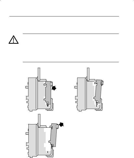
Removing an Extension Module
CAUTION. Electrostatic discharge (ESD) can damage components in the extension module and the oscilloscope. To prevent ESD, follow the steps on page 3 when installing, removing, or handling the extension modules.
After removing a module, install the dummy module cover to protect the contact pins.
1 |
2 |
3
4 |
TDS 200-Series Extension Module Instructions |

Getting Started
Installing an Extension Module
Make sure that you align the module connector to the oscilloscope connector pins before seating the module.
1 |
2 |
3 |
4 |
5
|
|
|
|
TDS 200-Series Extension Module Instructions |
5 |
||

Getting Started
Checking Module Installation
To check that the extension module is correctly installed, turn on the oscilloscope. The power-up screen should include the message ºExtension Module Passedº. If the oscilloscope does not recognize the extension module at power-up, do the steps in Troubleshooting Module Installation below.
Troubleshooting Module Installation
If the oscilloscope does not recognize the extension module at power-up, do the following steps:
1.Turn off the oscilloscope.
2.Follow the ESD precautions listed on page 3.
3.Disconnect all cables from the extension module.
4.Remove the extension module (refer to page 4).
5.Examine the oscilloscope option connector for bent, broken, or missing pins. If any pins are bent, carefully straighten them out.
6.Reinstall the extension module onto the oscilloscope.
7.Turn on the oscilloscope. If the oscilloscope still does not show the module installed, contact the nearest Tektronix service center.
6 |
TDS 200-Series Extension Module Instructions |
Loading...