


 Loading...
x
CSA8200 Communications Signal Analyzer
TDS8200 Digital Sampling Oscilloscope
Quick Start User Manual
*P071148202*
071-1482-02

CSA8200 Communications Signal Analyzer
TDS8200 Digital Sampling Oscilloscope
Quick Start User Manual
www.tektronix.com
Copyright © Tektronix. All rights reserved. Licensed software products are owned by Tektronix or its subsidiaries or suppliers, and are protected by national copyright laws and international treaty provisions.
Tektronix products are covered by U.S. and foreign patents, issued and pending. Information in this publication supercedes that in all previously published material. Specifications and price change privileges reserved.
TEKTRONIX, TEK, TEKPROBE, and FrameScan are registered trademarks of Tektronix, Inc.
Contacting Tektronix
Tektronix, Inc.
14200 SW Karl Braun Drive
P.O. Box 500
Beaverton, OR 97077
USA
For product information, sales, service, and technical support:
HIn North America, call 1-800-833-9200.
HWorldwide, visit www.tektronix.com to find contacts in your area.
Warranty 2
Tektronix warrants that this product will be free from defects in materials and workmanship for a period of one (1) year from the date of shipment. If any such product proves defective during this warranty period, Tektronix, at its option, either will repair the defective product without charge for parts and labor, or will provide a replacement in exchange for the defective product. Parts, modules and replacement products used by Tektronix for warranty work may be new or reconditioned to like new performance. All replaced parts, modules and products become the property of Tektronix.
In order to obtain service under this warranty, Customer must notify Tektronix of the defect before the expiration of the warranty period and make suitable arrangements for the performance of service. Customer shall be responsible for packaging and shipping the defective product to the service center designated by Tektronix, with shipping charges prepaid. Tektronix shall pay for the return of the product to Customer if the shipment is to a location within the country in which the Tektronix service center is located. Customer shall be responsible for paying all shipping charges, duties, taxes, and any other charges for products returned to any other locations.
This warranty shall not apply to any defect, failure or damage caused by improper use or improper or inadequate maintenance and care. Tektronix shall not be obligated to furnish service under this warranty a) to repair damage resulting from attempts by personnel other than Tektronix representatives to install, repair or service the product; b) to repair damage resulting from improper use or connection to incompatible equipment; c) to repair any damage or malfunction caused by the use of non-Tektronix supplies; or d) to service a product that has been modified or integrated with other products when the effect of such modification or integration increases the time or difficulty of servicing the product.
THIS WARRANTY IS GIVEN BY TEKTRONIX WITH RESPECT TO THE PRODUCT IN LIEU OF ANY OTHER WARRANTIES, EXPRESS OR IMPLIED. TEKTRONIX AND ITS VENDORS DISCLAIM ANY IMPLIED WARRANTIES OF MERCHANTABILITY OR FITNESS FOR A PARTICULAR PURPOSE. TEKTRONIX’ RESPONSIBILITY TO REPAIR OR REPLACE DEFECTIVE PRODUCTS IS THE SOLE AND EXCLUSIVE REMEDY PROVIDED TO THE CUSTOMER FOR BREACH OF THIS WARRANTY. TEKTRONIX AND ITS VENDORS WILL NOT BE LIABLE FOR ANY INDIRECT, SPECIAL, INCIDENTAL, OR CONSEQUENTIAL DAMAGES IRRESPECTIVE OF WHETHER TEKTRONIX OR THE VENDOR HAS ADVANCE NOTICE OF THE POSSIBILITY OF SUCH DAMAGES.

|
Table of Contents |
Table of Contents |
|
General Safety Summary . . . . . . . . . . . . . . . . . . . . . . . . . . . . . . . . . . . . . . . . . . . . . . . . . . . . . . . . . . . . . . . |
. . . . . . iii |
Preface . . . . . . . . . . . . . . . . . . . . . . . . . . . . . . . . . . . . . . . . . . . . . . . . . . . . . . . . . . . . . . . . . . . . . . . . . . . . . |
. . . . . v |
Documentation . . . . . . . . . . . . . . . . . . . . . . . . . . . . . . . . . . . . . . . . . . . . . . . . . . . . . . . . . . . . . . . . . . . . |
. . . . . v |
Conventions Used in this Manual . . . . . . . . . . . . . . . . . . . . . . . . . . . . . . . . . . . . . . . . . . . . . . . . . . . . . . . |
. . . . . vi |
Key Features . . . . . . . . . . . . . . . . . . . . . . . . . . . . . . . . . . . . . . . . . . . . . . . . . . . . . . . . . . . . . . . . . . . . . . . . . |
. . . . . 1 |
Install Your Instrument . . . . . . . . . . . . . . . . . . . . . . . . . . . . . . . . . . . . . . . . . . . . . . . . . . . . . . . . . . . . . . . . . . |
. . . . . 3 |
Standard Accessories . . . . . . . . . . . . . . . . . . . . . . . . . . . . . . . . . . . . . . . . . . . . . . . . . . . . . . . . . . . . . . . |
. . . . . 3 |
Operating Considerations . . . . . . . . . . . . . . . . . . . . . . . . . . . . . . . . . . . . . . . . . . . . . . . . . . . . . . . . . . . . |
. . . . . 4 |
Mechanical . . . . . . . . . . . . . . . . . . . . . . . . . . . . . . . . . . . . . . . . . . . . . . . . . . . . . . . . . . . . . . . . . . . |
. . . . . 4 |
Environmental . . . . . . . . . . . . . . . . . . . . . . . . . . . . . . . . . . . . . . . . . . . . . . . . . . . . . . . . . . . . . . . . . |
. . . . . 4 |
Power Supply . . . . . . . . . . . . . . . . . . . . . . . . . . . . . . . . . . . . . . . . . . . . . . . . . . . . . . . . . . . . . . . . . |
. . . . . 4 |
Input Connectors . . . . . . . . . . . . . . . . . . . . . . . . . . . . . . . . . . . . . . . . . . . . . . . . . . . . . . . . . . . . . . . |
. . . . . 4 |
Certifications . . . . . . . . . . . . . . . . . . . . . . . . . . . . . . . . . . . . . . . . . . . . . . . . . . . . . . . . . . . . . . . . . . |
. . . . . 4 |
Installing Modules . . . . . . . . . . . . . . . . . . . . . . . . . . . . . . . . . . . . . . . . . . . . . . . . . . . . . . . . . . . . . . . . . . |
. . . . . 5 |
Powering the Instrument On and Off . . . . . . . . . . . . . . . . . . . . . . . . . . . . . . . . . . . . . . . . . . . . . . . . . . . . . |
. . . . . 6 |
Creating an Emergency Startup Disk . . . . . . . . . . . . . . . . . . . . . . . . . . . . . . . . . . . . . . . . . . . . . . . . . . . . |
. . . . . 7 |
Adding a Second Monitor . . . . . . . . . . . . . . . . . . . . . . . . . . . . . . . . . . . . . . . . . . . . . . . . . . . . . . . . . . . . |
. . . . . 8 |
Changing the Windows Language . . . . . . . . . . . . . . . . . . . . . . . . . . . . . . . . . . . . . . . . . . . . . . . . . . . . . . |
. . . . . 10 |
Getting Acquainted with Your Instrument . . . . . . . . . . . . . . . . . . . . . . . . . . . . . . . . . . . . . . . . . . . . . . . . . . . . . |
. . . . . 12 |
Front Panel . . . . . . . . . . . . . . . . . . . . . . . . . . . . . . . . . . . . . . . . . . . . . . . . . . . . . . . . . . . . . . . . . . . . . . |
. . . . . 12 |
Rear Panel . . . . . . . . . . . . . . . . . . . . . . . . . . . . . . . . . . . . . . . . . . . . . . . . . . . . . . . . . . . . . . . . . . . . . . . |
. . . . . 12 |
Interface . . . . . . . . . . . . . . . . . . . . . . . . . . . . . . . . . . . . . . . . . . . . . . . . . . . . . . . . . . . . . . . . . . . . . . . . |
. . . . . 13 |
Control Panel . . . . . . . . . . . . . . . . . . . . . . . . . . . . . . . . . . . . . . . . . . . . . . . . . . . . . . . . . . . . . . . . . . . . . |
. . . . . 14 |
Display -- Single Graticule View . . . . . . . . . . . . . . . . . . . . . . . . . . . . . . . . . . . . . . . . . . . . . . . . . . . . . . . . |
. . . . . 15 |
Display -- Multiple Views . . . . . . . . . . . . . . . . . . . . . . . . . . . . . . . . . . . . . . . . . . . . . . . . . . . . . . . . . . . . . |
. . . . . 15 |
Accessing Online Help . . . . . . . . . . . . . . . . . . . . . . . . . . . . . . . . . . . . . . . . . . . . . . . . . . . . . . . . . . . . . . |
. . . . . 16 |
Inspect Your Instrument . . . . . . . . . . . . . . . . . . . . . . . . . . . . . . . . . . . . . . . . . . . . . . . . . . . . . . . . . . . . . . . . . |
. . . . . 18 |
Verify Internal Diagnostics Pass . . . . . . . . . . . . . . . . . . . . . . . . . . . . . . . . . . . . . . . . . . . . . . . . . . . . . . . . |
. . . . . 18 |
Optimizing Measurement Accuracy . . . . . . . . . . . . . . . . . . . . . . . . . . . . . . . . . . . . . . . . . . . . . . . . . . . . . . . . . |
. . . . . 20 |
Signal Path Compensation . . . . . . . . . . . . . . . . . . . . . . . . . . . . . . . . . . . . . . . . . . . . . . . . . . . . . . . . . . . |
. . . . . 20 |
Perform Dark-Level and User Wavelength Gain Compensations . . . . . . . . . . . . . . . . . . . . . . . . . . . . . . . . . |
. . . . . 22 |
Acquisition . . . . . . . . . . . . . . . . . . . . . . . . . . . . . . . . . . . . . . . . . . . . . . . . . . . . . . . . . . . . . . . . . . . . . . . . . . |
. . . . . 24 |
Setting Up Signal Input . . . . . . . . . . . . . . . . . . . . . . . . . . . . . . . . . . . . . . . . . . . . . . . . . . . . . . . . . . . . . . |
. . . . . 24 |
Using Autoset . . . . . . . . . . . . . . . . . . . . . . . . . . . . . . . . . . . . . . . . . . . . . . . . . . . . . . . . . . . . . . . . . . . . . |
. . . . . 26 |
Using Default Setup . . . . . . . . . . . . . . . . . . . . . . . . . . . . . . . . . . . . . . . . . . . . . . . . . . . . . . . . . . . . . . . . |
. . . . . 26 |
Accessing the Setup Dialog Boxes . . . . . . . . . . . . . . . . . . . . . . . . . . . . . . . . . . . . . . . . . . . . . . . . . . . . . . |
. . . . . 27 |
Changing the Acquisition Mode . . . . . . . . . . . . . . . . . . . . . . . . . . . . . . . . . . . . . . . . . . . . . . . . . . . . . . . . |
. . . . . 28 |
Setting the Display Style . . . . . . . . . . . . . . . . . . . . . . . . . . . . . . . . . . . . . . . . . . . . . . . . . . . . . . . . . . . . . |
. . . . . 29 |
Triggers . . . . . . . . . . . . . . . . . . . . . . . . . . . . . . . . . . . . . . . . . . . . . . . . . . . . . . . . . . . . . . . . . . . . . . . . . . . . . |
. . . . . 30 |
Triggering Concepts . . . . . . . . . . . . . . . . . . . . . . . . . . . . . . . . . . . . . . . . . . . . . . . . . . . . . . . . . . . . . . . . |
. . . . . 30 |
Trigger Event . . . . . . . . . . . . . . . . . . . . . . . . . . . . . . . . . . . . . . . . . . . . . . . . . . . . . . . . . . . . . . . . . . |
. . . . . 30 |
Trigger Type . . . . . . . . . . . . . . . . . . . . . . . . . . . . . . . . . . . . . . . . . . . . . . . . . . . . . . . . . . . . . . . . . . |
. . . . . 30 |
Trigger Modes . . . . . . . . . . . . . . . . . . . . . . . . . . . . . . . . . . . . . . . . . . . . . . . . . . . . . . . . . . . . . . . . . |
. . . . . 30 |
Trigger Sources . . . . . . . . . . . . . . . . . . . . . . . . . . . . . . . . . . . . . . . . . . . . . . . . . . . . . . . . . . . . . . . . |
. . . . . 30 |
Trigger Source Connectors . . . . . . . . . . . . . . . . . . . . . . . . . . . . . . . . . . . . . . . . . . . . . . . . . . . . . . . . |
. . . . . 31 |
Gated Trigger Connector (Option GT Equipped) . . . . . . . . . . . . . . . . . . . . . . . . . . . . . . . . . . . . . . . . . |
. . . . . 32 |
Enhanced Triggering . . . . . . . . . . . . . . . . . . . . . . . . . . . . . . . . . . . . . . . . . . . . . . . . . . . . . . . . . . . . |
. . . . . 32 |
Trigger Holdoff . . . . . . . . . . . . . . . . . . . . . . . . . . . . . . . . . . . . . . . . . . . . . . . . . . . . . . . . . . . . . . . . . |
. . . . . 32 |
Setting Trigger Controls . . . . . . . . . . . . . . . . . . . . . . . . . . . . . . . . . . . . . . . . . . . . . . . . . . . . . . . . . . . . . . |
. . . . . 34 |
Setting Pattern Sync Controls . . . . . . . . . . . . . . . . . . . . . . . . . . . . . . . . . . . . . . . . . . . . . . . . . . . . . . . . . |
. . . . . 35 |
Checking Trigger Status . . . . . . . . . . . . . . . . . . . . . . . . . . . . . . . . . . . . . . . . . . . . . . . . . . . . . . . . . . . . . |
. . . . . 36 |
CSA8200 & TDS8200 Series Quick Start User Manual |
i |

Table of Contents |
|
Analyzing Waveforms . . . . . . . . . . . . . . . . . . . . . . . . . . . . . . . . . . . . . . . . . . . . . . . . . . . . . . . . . . . . . . . . . . . . . . . . |
37 |
Taking Automatic Measurements . . . . . . . . . . . . . . . . . . . . . . . . . . . . . . . . . . . . . . . . . . . . . . . . . . . . . . . . . . . . |
37 |
Turning Off Automatic Measurements . . . . . . . . . . . . . . . . . . . . . . . . . . . . . . . . . . . . . . . . . . . . . . . . . . . . . . . . . |
41 |
Cursor Measurements . . . . . . . . . . . . . . . . . . . . . . . . . . . . . . . . . . . . . . . . . . . . . . . . . . . . . . . . . . . . . . . . . . . . |
42 |
Math Waveforms . . . . . . . . . . . . . . . . . . . . . . . . . . . . . . . . . . . . . . . . . . . . . . . . . . . . . . . . . . . . . . . . . . . . . . . |
44 |
Waveform Databases . . . . . . . . . . . . . . . . . . . . . . . . . . . . . . . . . . . . . . . . . . . . . . . . . . . . . . . . . . . . . . . . . . . . |
46 |
Display a Communication Signal . . . . . . . . . . . . . . . . . . . . . . . . . . . . . . . . . . . . . . . . . . . . . . . . . . . . . . . . . . . . |
47 |
Display and Analyze Communication Signals Using Mask Testing . . . . . . . . . . . . . . . . . . . . . . . . . . . . . . . . . . . . . |
48 |
FrameScan . . . . . . . . . . . . . . . . . . . . . . . . . . . . . . . . . . . . . . . . . . . . . . . . . . . . . . . . . . . . . . . . . . . . . . . . . . . |
51 |
To Use TDR . . . . . . . . . . . . . . . . . . . . . . . . . . . . . . . . . . . . . . . . . . . . . . . . . . . . . . . . . . . . . . . . . . . . . . . . . . . |
52 |
Phase Reference . . . . . . . . . . . . . . . . . . . . . . . . . . . . . . . . . . . . . . . . . . . . . . . . . . . . . . . . . . . . . . . . . . . . . . . |
53 |
Histograms . . . . . . . . . . . . . . . . . . . . . . . . . . . . . . . . . . . . . . . . . . . . . . . . . . . . . . . . . . . . . . . . . . . . . . . . . . . . |
54 |
Document Your Results . . . . . . . . . . . . . . . . . . . . . . . . . . . . . . . . . . . . . . . . . . . . . . . . . . . . . . . . . . . . . . . . . . . |
55 |
Using the 80A05 Electrical Clock Recovery Module Examples . . . . . . . . . . . . . . . . . . . . . . . . . . . . . . . . . . . . . . . . . . . |
56 |
Clock Recovery / Trigger on Recovered Clock . . . . . . . . . . . . . . . . . . . . . . . . . . . . . . . . . . . . . . . . . . . . . . . . . . . |
57 |
Clock Recovery / Trigger for Optical Signal, with the 80C12 Optical Module . . . . . . . . . . . . . . . . . . . . . . . . . . . . . |
58 |
Differential Clock Recovery and Acquisition . . . . . . . . . . . . . . . . . . . . . . . . . . . . . . . . . . . . . . . . . . . . . . . . . . . . |
59 |
Probing with Low-impedance Probes . . . . . . . . . . . . . . . . . . . . . . . . . . . . . . . . . . . . . . . . . . . . . . . . . . . . . . . . . |
60 |
Probing with Differential to Single-ended Probes . . . . . . . . . . . . . . . . . . . . . . . . . . . . . . . . . . . . . . . . . . . . . . . . . |
61 |
Vertical Gain Adjustment . . . . . . . . . . . . . . . . . . . . . . . . . . . . . . . . . . . . . . . . . . . . . . . . . . . . . . . . . . . . . . . . . . |
62 |
Skew and Deskewing . . . . . . . . . . . . . . . . . . . . . . . . . . . . . . . . . . . . . . . . . . . . . . . . . . . . . . . . . . . . . . . . . . . . . . . . |
63 |
Sources of Skew . . . . . . . . . . . . . . . . . . . . . . . . . . . . . . . . . . . . . . . . . . . . . . . . . . . . . . . . . . . . . . . . . . . . . . . . |
63 |
Minimizing Skew . . . . . . . . . . . . . . . . . . . . . . . . . . . . . . . . . . . . . . . . . . . . . . . . . . . . . . . . . . . . . . . . . . . . . . . . |
64 |
Measuring Skew . . . . . . . . . . . . . . . . . . . . . . . . . . . . . . . . . . . . . . . . . . . . . . . . . . . . . . . . . . . . . . . . . . . . . . . . |
64 |
Methods to Deskew Your Signals . . . . . . . . . . . . . . . . . . . . . . . . . . . . . . . . . . . . . . . . . . . . . . . . . . . . . . . . . . . . |
64 |
Methods to Adjust Out Skew . . . . . . . . . . . . . . . . . . . . . . . . . . . . . . . . . . . . . . . . . . . . . . . . . . . . . . . . . . . . . . . |
66 |
Differential TDR Deskew Method . . . . . . . . . . . . . . . . . . . . . . . . . . . . . . . . . . . . . . . . . . . . . . . . . . . . . . . . . . . . |
67 |
Configuration/Setup Considerations . . . . . . . . . . . . . . . . . . . . . . . . . . . . . . . . . . . . . . . . . . . . . . . . . . . . . . |
67 |
Performing Acquisition Deskew . . . . . . . . . . . . . . . . . . . . . . . . . . . . . . . . . . . . . . . . . . . . . . . . . . . . . . . . . . |
68 |
Performing TDR Step Deskew . . . . . . . . . . . . . . . . . . . . . . . . . . . . . . . . . . . . . . . . . . . . . . . . . . . . . . . . . . |
69 |
Cleaning the Instrument . . . . . . . . . . . . . . . . . . . . . . . . . . . . . . . . . . . . . . . . . . . . . . . . . . . . . . . . . . . . . . . . . . . . . . |
71 |
Exterior Cleaning . . . . . . . . . . . . . . . . . . . . . . . . . . . . . . . . . . . . . . . . . . . . . . . . . . . . . . . . . . . . . . . . . . . . . . . |
71 |
Flat Panel Display Cleaning . . . . . . . . . . . . . . . . . . . . . . . . . . . . . . . . . . . . . . . . . . . . . . . . . . . . . . . . . . . . . . . . |
71 |
Optical Connector Cleaning . . . . . . . . . . . . . . . . . . . . . . . . . . . . . . . . . . . . . . . . . . . . . . . . . . . . . . . . . . . . . . . . |
71 |
Index . . . . . . . . . . . . . . . . . . . . . . . . . . . . . . . . . . . . . . . . . . . . . . . . . . . . . . . . . . . . . . . . . . . . . . . . . . . . . . . . . . . |
73 |
ii |
CSA8200 & TDS8200 Series Quick Start User Manual |

General Safety Summary
General Safety Summary
Review the following safety precautions to avoid injury and prevent damage to this product or any products connected to it.
To avoid potential hazards, use this product only as specified.
Only qualified personnel should perform service procedures.
While using this product, you may need to access other parts of the system. Read the General Safety Summary in other system manuals for warnings and cautions related to operating the system.
To Avoid Fire or Personal Injury
Use Proper Power Cord. Use only the power cord specified for this product and certified for the country of use.
Connect and Disconnect Properly. Do not connect or disconnect probes or test leads while they are connected to a voltage source.
Ground the Product. This product is grounded through the grounding conductor of the power cord. To avoid electric shock, the grounding conductor must be connected to earth ground. Before making connections to the input or output terminals of the product, ensure that the product is properly grounded.
Observe All Terminal Ratings. To avoid fire or shock hazard, observe all ratings and markings on the product. Consult the product manual for further ratings information before making connections to the product.
Do not apply a potential to any terminal, including the common terminal, that exceeds the maximum rating of that terminal.
Power Disconnect. The power switch disconnects the product from the power source. See instructions for the location. Do not block the power switch; it must remain accessible to the user at all times.
Do Not Operate Without Covers. Do not operate this product with covers or panels removed.
Use Proper Fuse. Use only the fuse type and rating specified for this product.
Avoid Exposed Circuitry. Do not touch exposed connections and components when power is present.
Wear Eye Protection. Wear eye protection if exposure to high-intensity rays or laser radiation exists.
Do Not Operate With Suspected Failures. If you suspect there is damage to this product, have it inspected by qualified service personnel.
Do Not Operate in Wet/Damp Conditions.
Do Not Operate in an Explosive Atmosphere.
Keep Product Surfaces Clean and Dry.
Provide Proper Ventilation. Refer to the manual’s installation instructions for details on installing the product so it has proper ventilation.
Symbols and Terms
Terms in this Manual. These terms may appear in this manual:
CSA8200 & TDS8200 Series Quick Start User Manual |
iii |
General Safety Summary
WARNING. Warning statements identify conditions or practices that could result in injury or loss of life.
CAUTION. Caution statements identify conditions or practices that could result in damage to this product or other property.
Terms on the Product. These terms may appear on the product:
DANGER indicates an injury hazard immediately accessible as you read the marking.
WARNING indicates an injury hazard not immediately accessible as you read the marking.
CAUTION indicates a hazard to property including the product.
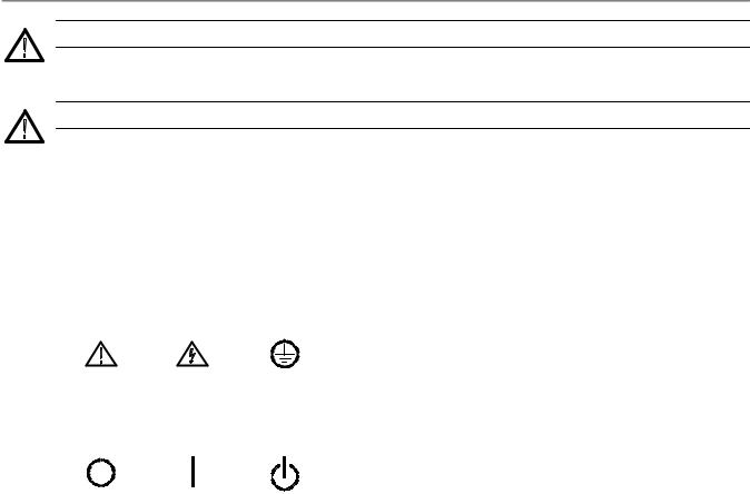
Symbols on the Product. The following symbols may appear on the product:
CAUTION |
WARNING |
Protective Ground |
Refer to Manual |
High Voltage |
(Earth) Terminal |
Mains Disconnected |
Mains Connected |
Standby |
|
OFF (Power) |
ON (Power) |
||
|
iv |
CSA8200 & TDS8200 Series Quick Start User Manual |
Preface
Preface
Documentation
This manual describes the installation and operation of CSA8200 & TDS8200 Series Instruments along with basic operations and concept. For more detailed information, see the online help on your instrument.
NOTE. The screen images in this manual are based on product software version 2.5 and may differ slightly from other versions of product software.
Additional information is available through a variety of sources. The following information map points to the location of different types of information available for this product.
Quick Start User Manual |
WWW.Tektronix.com |
Unpacking, Installation, Operation & |
|
|
Overviews |
PDF files of 8000 series |
In-depth Operation, |
instrument & modules |
UI Help, Programming Help |
manuals |
Analysis & Connectivity Tools |
Product
Documentation |
Online Help |
|
|
||
CD |
Analysis & |
|
Demo |
||
Connectivity Tools |
||
Applications |
||
Getting Started |
||
Demo |
||
with |
||
Applications |
||
OpenChoiceTM |
||
Software CD |
||
Solutions Manual |
||
|
||
Product Software |
System Restore |
|
Software |
||
|
Product Software |
System Restore |
Booklet |
Booklet |
Performance |
|
Verification and |
Self-service |
Specifications |
|
Product |
|
Documentation |
Optional Service |
CD |
Manual |
CSA8200 & TDS8200 Series Quick Start User Manual |
v |
Preface
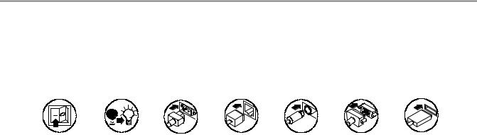
Conventions Used in this Manual
The following icons are used throughout this manual.
Rear panel |
Front panel |
Connect pow- |
Network |
PS2 |
SVGA |
USB |
||
power |
power |
er |
|
|
|
|
||
|
|
|
|
|
|
|
|
|
|
|
|
|
|
|
|
|
|
vi |
CSA8200 & TDS8200 Series Quick Start User Manual |

Key Features
Key Features
The CSA8200 and TDS8200 Series instruments are high-speed, precision sampling systems that find use in validation and conformance testing and impedance verification for:
HHigh-performance semiconductor/computer applications, such as semiconductor testing, TDR characterization of circuit boards, IC packages and cables, and high-speed serial digital data communications.
HHigh-performance communications applications, such as design evaluation and manufacturing test of datacom and telecom components, transceiver subassemblies, and transmission systems.
The instruments include a user interface that runs on the Microsoft Windows 2000 operating system as a windowed application. You operate the instrument using front-panel controls with the mouse and keyboard or with the touch screen.
Features Include:
HIndustry-leading waveform acquisition and measurement rate, with Sample, Envelope, and Average acquisition modes.
HSupport for up to six sampling modules (two large and four small modules). Up to eight inputs can be active at a time.
HSupports integrated optical and/or electrical signal pick-off and clock recovery, enabling accurate triggering on optical and/or electrical communication-signals.
HSupport for optical modules with several integrated, selectable reference receivers, which eliminates the need for a multitude of add-on reference receivers.
HFull programmability, with an extensive GPIB-command set and a message-based interface.
HTrue differential TDR, with fast step (15 psec reflected risetime) when used with a TDR-capable 80E10 sampling module.
HIndustry-leading trigger bandwidth (12+ GHz) when using the built-in-prescaler.
HSupport of both telecom (SONET and SDH) and datacom (Fibre Channel, Infiniband, and Gigabit Ethernet) optical communication standards.
HPowerful built-in measurement capability, including histograms, mask testing, and automatic measurements.
HAutomatic measurements operate on Pulses, RZ eye patterns, and NRZ eye patterns.
HDC to 65 GHz optical bandwidth; DC to 70+ GHz electrical bandwidth, with up to 12.5 GHz triggering.
NOTE. Bandwidth is determined by the specific modules that are installed.
HLow jitter (200 fs typical) in phase reference modes with the 82A04 Phase Reference module.
HFrameScan acquisition for isolating data-dependent failures during conformance/performance testing and for examining very low-level repetitive signals.
HJitter analysis with the 80SJNB Advanced Jitter, Noise and BER Analysis Software for the TDS/CSA8000 Series Sampling Oscilloscopes application (requires software key). Refer to the 8000 Series Product Software CD-ROM booklet for free trial information and software key use.
HPattern (frame) triggering with the 80A06 PatternSync Trigger module.
CSA8200 & TDS8200 Series Quick Start User Manual |
1 |

Key Features
HImproved acquisition throughput and timing accuracy using the PatternSync Trigger module in conjunction with FrameScan.
HSupport for optical conformance testing of SONET/SDH signals (including the various forward error correction rates for these telecom rates) from 155 Mbps to 43 Gb/s, FibreChannel signals, and 1, 2, and 10 Gigabit Ethernet signals as well as 2.5 Gb/s Infiniband signals.
NOTE. Support for conformance testing rates is determined by the specific modules that are installed.
HHigh precision time base with two modes of operation, locked and short-term jitter-optimized.
HNegligible long-term jitter degradation (<0.1 ppm), which substantially improves the ability to view signals that are delayed far from the trigger point without distortion.
HImproved short-term and long-term trigger jitter.
HA gated trigger option (Option GT) that lets you disable or enable (gate) triggering based on a TTL signal you connect to the instrument rear panel. This Option allows you to use recirculating buffers as part of your test setup to simulate the effects of very long optical links that are typical of undersea cables and long terrestrial links.
HAnalysis and connectivity tools enable the instrument to be controlled from a variety of local and remote environments and to share data with other commercially available analysis programs.
HPredefined, built-in masks in addition to the user-defined masks.
HA large 10-inch color display that supports color grading of waveform data to show sample density.
HAn intuitive UI (User Interface), with built-in online help displayable on screen.
2 |
CSA8200 & TDS8200 Series Quick Start User Manual |

Install Your Instrument
Install Your Instrument
Unpack the instrument and check that you received all items listed as Standard Accessories. Recommended accessories and probes, instrument options, and upgrades are listed in the online help. Check the Tektronix Web site (www.tektronix.com) for the most current information.
Standard Accessories
Accessory |
Tektronix part number |
|
|
|
|
CSA8200 Communications Signal Analyzer |
071-1482-xx |
|
TDS8200 Digital Sampling Oscilloscope |
|
|
Quick Start User Manual |
|
|
|
|
|
Certificate of Traceable Calibration for product at initial shipment |
Not orderable |
|
|
|
|
Business reply card |
Not orderable |
|
|
|
|
1 |
Windows compatible keyboard |
119-B146-00 |
|
|
|
1 |
Windows compatible mouse |
119-6936-00 |
|
|
|
1 |
Instrument front cover |
200-4519-00 |
|
|
|
1 |
Accessory pouch |
016-1441-00 |
|
|
|
2 |
Touchscreen styluses |
119-6107-00 |
|
|
|
1 |
ESD wrist strap with 6 foot coiled cord |
006-3415-04 |
|
|
|
CSA8000 & TDS8000 Series Product Documentation Kit (CD) |
020-2543-xx |
|
|
|
|
CSA8000 & TDS8000 Online Help (part of application software) |
Not orderable |
|
|
|
|
CSA8000 & TDS8000 Programmer Online Guide (part of application software) |
Not orderable |
|
|
|
|
Oscilloscope Analysis and Connectivity Made Easy (manual and CD with connectivity |
020-2449-xx |
|
examples) |
|
|
|
|
|
CSA8000 & TDS8000 Series Windows 2000 OS Restore Kit |
020-2527-xx |
|
|
|
|
CSA8000 & TDS8000 Series Product Software Kit |
020-2526-xx |
|
|
|
|
8000 Series Demo Applications Software CD |
020-2480-xx |
|
|
|
|
1 |
Power cord |
Type dependent on |
|
|
selection during order |
|
|
placement |
|
|
|
CSA8200 & TDS8200 Series Quick Start User Manual |
3 |
Install Your Instrument
Operating Considerations
The following information lists the specifications related to the operation of the mainframe. Refer to the Specifications and Performance Verification manual for a complete list of specifications.
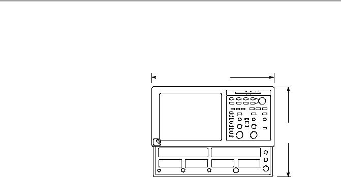
Mechanical
Clearance: |
|
457 mm |
|
|
(18 in.) |
HTop, Front, and Rear: 0 in (0 mm)
HSides: 2 in (51 mm)
HBottom: 0.75 in (19 mm)
Weight:
H19.5 kg (43.0 lb.). This does not include any accessories or modules.
343 mm
(13.5 in.)
|
Depth = 419 mm (16.5 in.) |
Environmental |
|
Temperature |
10 °C to +40 °C |
Relative humidity |
20% to 80%, with a maximum wet bulb temperature of 29 °C at or |
|
below +40 °C |
Altitude |
3,000 m (approximately 10,000 ft.) |
Power Supply |
|
Source voltage and Frequency |
100 -- 240 VRMS ±10%, 50 -- 60 Hz or 115 VRMS ±10%, 400 Hz |
Power Consumption |
240 watts (fully loaded); 160 watts (mainframe alone with no modules) |
Input Connectors |
|
Trigger Direct Input range |
±1.5 V (DC + peak AC) maximum input voltage |
Trigger Prescaled Input absolute maximum |
±2.5 Vp-p |
input (typical) |
|
External 10 MHz Reference Input |
500 mVp-p to 5 Vp-p AC coupled into 1 kΩ, ±5 V maximum |
Gated Trigger Input non-destruct levels |
±5 V maximum |
(Option GT equipped mainframes) |
|
Certifications |
|
Pollution Degree |
Pollution Degree 2. Note: Rated for indoor use only. |
4 |
CSA8200 & TDS8200 Series Quick Start User Manual |

Install Your Instrument
Installing Modules
CAUTION. Never install or remove modules while the instrument is powered on.
Use an ESD wrist strap when installing or removing modules and when connecting signals to the module inputs.
Do not transport or ship the instrument with modules installed.
1. Always use an ESD wrist strap (provided) when installing and removing modules.
2. You can install up to two large sampling modules and four small modules for a total of 8 inputs.
1 |
Small-module compartment (4) |
Large-module compartment (2)
Following are some typical module installations illustrating the interaction between large compartment channels and small compartment channels.
NOTE. A large compartment module that only derives power from the compartment does not use any small compartment input channels.
Eight channels: No large and four small |
CH1 Module not installed |
|
|
CH3 Module not installed |
|
|||
modules |
|
|
|
|||||
|
|
|
|
|
|
|
|
|
|
CH 1 |
CH 2 |
CH 3 |
CH 4 |
CH 5 |
CH 6 |
CH 7 |
CH 8 |
Six channels: Two large modules and two |
|
CH1 module installed |
|
|
CH3 module installed |
|
||
small modules |
|
|
|
|
||||
|
|
|
|
|
|
|
|
|
|
CH 1 |
CH 2 |
CH 3 |
CH 4 |
CH 5 |
CH 6 |
CH 7 |
CH 8 |
|
N.A. |
N.A. |
N.A. |
N.A. |
||||
|
|
|
|
|
||||
Seven channels: One large module, installed in CH3 compartment and three small modules
|
CH1 module not installed |
|
|
|
CH3 module installed |
|
||
CH 1 |
CH 2 |
CH 3 |
CH 4 |
|
CH 5 |
CH 6 |
CH 7 |
CH 8 |
|
||||||||
N.A. |
N.A. |
|
||||||
|
|
|
|
|
|
|
||
Seven channels: One large module, installed in CH1 compartment and three small modules
|
CH1 module installed |
|
|
CH3 module not installed |
|
|||
CH 1 |
CH 2 |
CH 3 |
CH 4 |
CH 5 |
CH 6 |
CH 7 |
CH 8 |
|
N.A. |
N.A. |
|||||||
|
|
|
|
|
|
|||
CSA8200 & TDS8200 Series Quick Start User Manual |
5 |
Install Your Instrument
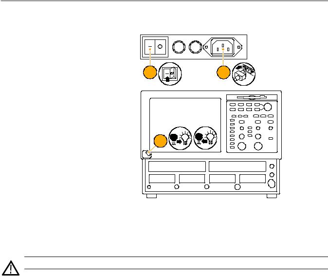
Powering the Instrument On and Off
1. Insert AC power cord.
2. Toggle the mains switch to on.
2 |
1 |
3.Use the front panel power button to switch the instrument on and off.
3
Quick Tip
HWhen turning off the instrument, Windows and all applications automatically shut down before the instrument powers off.
CAUTION. To prevent damaging the modules, do not install or remove any modules while the instrument is powered on.
6 |
CSA8200 & TDS8200 Series Quick Start User Manual |
Install Your Instrument
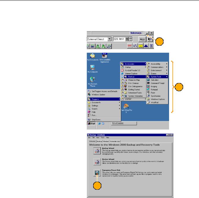
Creating an Emergency Startup Disk
Create an emergency startup disk that you can use to restart your instrument in case of a major hardware or software failure. Store this disk in a safe place.
1. Select the minimize icon, gaining
access to the Start menu.
1
2.Select Start > Programs > Accessories > System Tools > Backup.
2
3.Select Emergency Repair Disk and follow the on-screen instructions.
3
CSA8200 & TDS8200 Series Quick Start User Manual |
7 |
Install Your Instrument
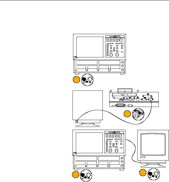
Adding a Second Monitor
You can operate the instrument while using Windows and installed applications on an external monitor. Use the Settings tab in the Windows Display Properties dialog box to set up a dual-monitor configuration. Both the oscilloscope and the second monitor must have the color setting set to True Color.
1. Power off the instrument.
1
2. Connect a video cable (not supplied) from the video port on the back of the instrument to the external monitor.
External monitor
2
3.Power on the instrument.
4.Power on the external monitor.
3 |
4 |
|
8 |
CSA8200 & TDS8200 Series Quick Start User Manual |
Install Your Instrument
5.In the Start menu, select Settings and then Control Panel.
5
6. |
Select Display. |
|
|
|
6 |
7. |
In the Display Properties window, se- |
|
|
lect the Settings tab. |
7 |
8.Select the second monitor.
9.Select Extend my Windows desktop onto this monitor. Make sure that both monitors are set to True Color.
10.Click Apply, and then click OK.
8
9
10
CSA8200 & TDS8200 Series Quick Start User Manual |
9 |
Install Your Instrument
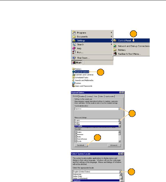
Changing the Windows Language
Use the following procedure to change the Windows language from English to one of your choice. This procedure does not change the language of the user interface or the online help in the TekScope application. Before you begin, minimize the TekScope application.
1. Select Settings and then select Con- |
1 |
|
trol Panel. |
||
|
2. Select Regional Options.
2
3.Select your locale, and then select your menus and dialogs language.
4.Click Set default....
3
4
5. Select locale.
5
10 |
CSA8200 & TDS8200 Series Quick Start User Manual |

Install Your Instrument
6. Click Add to add the input locale.
6
7.Select the Input locale and Keyboard layout/IME.
7
8.Select the Installed input locale, and click Set as Default.
9.Click OK.
 8
8
9
10. Click Yes in each dialog box.
10
CSA8200 & TDS8200 Series Quick Start User Manual |
11 |
Getting Acquainted with Your Instrument
Getting Acquainted with Your Instrument
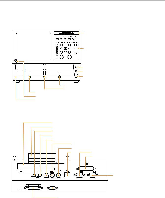
Front Panel
Floppy disk drive
Control panel
Internal clock output
DC calibration output
External 10 MHz reference input
Trigger probe power
Trigger direct input
Trigger prescale input
On/Off switch
Ground terminal
Rear Panel
CD-ROM drive
Removable hard drive
Audio line out
Audio line in (microphone)
USB (keyboard)
PS2 (keyboard) |
|
PS2 (mouse) |
|
LAN |
COM 1 |
|
Parallel port |
 Scope VGA output for instrument display
GPIB
SVGA out for dual-monitor display
 Gated trigger Option GT (lower right corner)
12 |
CSA8200 & TDS8200 Series Quick Start User Manual |
Getting Acquainted with Your Instrument
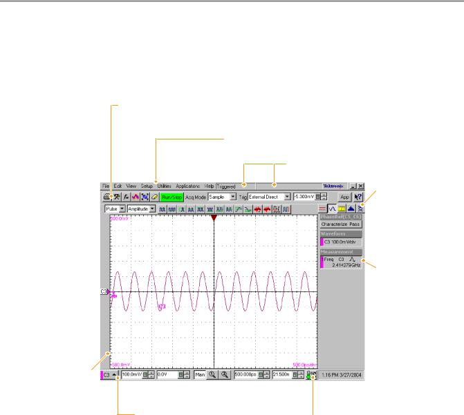
Interface
The menu bar provides access to commands that control all of the instrument features and functions. The toolbar provides access to the most common features.
Hovering the cursor over button or setting displays a brief description of its function, called a tooltip.
Measurements Bar:
Access to automated measurements by signal
type and category; click  measurement buttons to
measure the selected waveform
Display: Live, reference,  and math waveforms
display here, along with cursors, masks, etc. to analyze them
Waveform Bar: Access to waveform selection (click), waveform position (drag), and waveform properties (right-click)
Tool Bar: Access to key features: printing, setup dialogs, math setup, waveform database, autoset, clear data, acquisition mode, triggering, and applications
Menu Bar: Access to data I/O, printing, online help system, and set-up functions
Controls Bar: Quick access to waveforms and timebases for display, and to their scale, offset, and position controls for adjustment
Status Bar: Trigger status and waveform count
Readout Bar: Toggle individual readouts on and off by clicking its button
 Phase Reference Status:
Indicates the characterization status of the phase reference module
A Readout: Right click any readout to display a short-cut menu providing handy access to often-used setup controls and properties for the feature associated with the readout
 Readouts: Display up to five readouts in this area, selectable from the Readout Bar
 Compensation Indicator: Indicates the compensation status of modules and mainframe
CSA8200 & TDS8200 Series Quick Start User Manual |
13 |
Getting Acquainted with Your Instrument
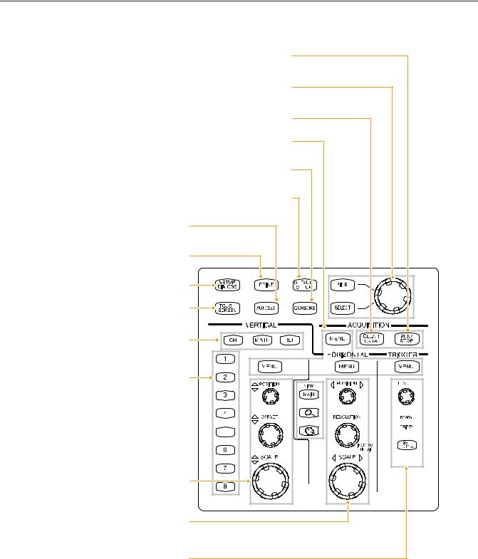
Control Panel
Start and stop acquisition.
Adjust most control fields in setup dialogs. Press the Select button to switch among fields.
Press the Fine button to toggle between normal and fine adjustment.
Clear all channel waveforms at once.
Menu buttons quickly access the setup dialog for its control group for more detailed setup.
Display measurement cursors and assign the knob and Select buttons to control them.
Quickly return to instrument-default control settings.
Optimize instrument settings for selected channels.
Access print dialog for printing the display.
Display the cluster of Setup Dialogs for comprehensive setup of the instrument.
Toggle the touch screen on and off. Use the touch screen to control UI when you haven’t installed a mouse.
Select a waveform type, Channel, Reference, or Math, to display or adjust on screen (selected button lights).
Select among displayed waveforms or display and select a waveform. Press selected waveform to tun it off. Button lights indicate displayed and selected waveforms.
Select among displayed timebase views or display and  select a timebase view. Press selected view to turn it off
(except main, which is always on).
Vertically scale, position, and offset selected waveform.
Horizontally scale, position, and set record length of selected waveform.
Set trigger level and use lights to monitor trigger state.
14 |
CSA8200 & TDS8200 Series Quick Start User Manual |
Loading...