


User Manual
TDS 620A, 640A & 644A
Digitizing Oscilloscopes
070-8715-04
Copyright Tektronix, Inc., 1993. All rights reserved.
Tektronix products are covered by U.S. and foreign patents, issued and pending. Information in this publication supercedes that in all previously published material. Specifications and price change privileges reserved.
Printed in the U.S.A.
Tektronix, Inc., P.O. Box 1000, Wilsonville, OR 97070±1000
TEKTRONIX, TEK, TEKPROBE, and SCOPE-MOBILE are registered trademarks of Tektronix, Inc.
Microsoft is a registered trademark of Microsoft Corporation.
IBM is a registered trademark of International Business Machines.
GPIB-PCII and GPIB-PCIIA are registered trademarks of National Instruments Corporation. Epson is a registered trademark of Epson America, Inc.
Interleaf is a trademark of Interleaf, Inc.
PostScript is a registered trademark of Adobe Systems Incorporated.
Deskjet, Laserjet, and Thinkjet are registered trademarks of Hewlett-Packard Corporation.
WARRANTY
Tektronix warrants that the products that it manufactures and sells will be free from defects in materials and workmanship for a period of three (3) years from the date of shipment. If a product proves defective during this warranty period, Tektronix, at its option, either will repair the defective product without charge for parts and labor, or will provide a replacement in exchange for the defective product.
In order to obtain service under this warranty, Customer must notify Tektronix of the defect before the expiration of the warranty period and make suitable arrangements for the performance of service. Customer shall be responsible for packaging and shipping the defective product to the service center designated by Tektronix, with shipping charges prepaid. Tektronix shall pay for the return of the product to Customer if the shipment is to a location within the country in which the Tektronix service center is located. Customer shall be responsible for paying all shipping charges, duties, taxes, and any other charges for products returned to any other locations.
This warranty shall not apply to any defect, failure or damage caused by improper use or improper or inadequate maintenance and care. Tektronix shall not be obligated to furnish service under this warranty a) to repair damage resulting from attempts by personnel other than Tektronix representatives to install, repair or service the product; b) to repair damage resulting from improper use or connection to incompatible equipment; c) to repair any damage or malfunction caused by the use of non-Tektronix supplies; or d) to service a product that has been modified or integrated with other products when the effect of such modification or integration increases the time or difficulty of servicing the product.
THIS WARRANTY IS GIVEN BY TEKTRONIX IN LIEU OF ANY OTHER WARRANTIES, EXPRESS OR IMPLIED. TEKTRONIX AND ITS VENDORS DISCLAIM ANY IMPLIED WARRANTIES OF MERCHANTABILITY OR FITNESS FOR A PARTICULAR PURPOSE. TEKTRONIX' RESPONSIBILITY TO REPAIR OR REPLACE DEFECTIVE PRODUCTS IS THE SOLE AND EXCLUSIVE REMEDY PROVIDED TO THE CUSTOMER FOR BREACH OF THIS WARRANTY. TEKTRONIX AND ITS VENDORS WILL NOT BE LIABLE FOR ANY INDIRECT, SPECIAL, INCIDENTAL, OR CONSEQUENTIAL DAMAGES IRRESPECTIVE OF WHETHER TEKTRONIX OR THE VENDOR HAS ADVANCE NOTICE OF THE POSSIBILITY OF SUCH DAMAGES.

rm l rm
'35+(+%#5' 0( 5*' #/6(#%563'3 .1035'3
' *'3'$9 %'35+(9 5*#5 5*' 6 64 #/& 644 4%+--04%01'4 #/& #-- (#%5039@+/45#--'& 015+0/4 %0.1-+'4 8+5* 5*' /5'3('3'/%' 6113'44+0/ 3'26+3'.'/54 0( 045#- ')6-#5+0/ () 4 .'/&'& 1'3 () 46
*' '3.#/ 045#- '37+%' 8#4 /05+(+'& 5*#5 5*' '26+1.'/5 +4 $'+/) .#3,'5'&
*' '3.#/ 045#- '37+%' *#4 5*' 3+)*5 50 3'@5'45 5*' 4'3+'4 #/& 50 7'3+(9 5*#5 +5 %0.1-+'4
!
'4%*'+/+)6/) &'4 '345'--'34 .1035'634
+'3.+5 8+3& $'4%*'+/+)5 < &'3 &+' 6 64 #/& 644 4%+--04%01'4 6/& #--' (#$3+,+/45#--+'35'/ 15+0/'/ +/ ;$'3'+/45+..6/) .+5 &'/ '45+..6/)'/ &'3 .54$-#55@ '3(?)6/) ()4 6/& "64#5:7'3(?)6/) 46 (6/,'/545>35 4+/&
'3 '654%*'/ 6/&'41045 863&' /7'3,'*3$3+/)'/ &+'4'4 '3=5'4 #/)':'+)5 6/& &+' '3'%*5+)6/) :63 ;$'313?(6/) &'3 '3+' #6( +/*#-5'/ &'3 '45+..6/)'/ '+/)'3=6.5
!
50 5*' 64'3 01'3#503:
*' '3.#/ 045#- '37+%' 3'26+3'4 5*#5 945'.4 #44'.$-'& $9 5*' 01'3#503 64'3 0( 5*+4 +/4536.'/5 .645
#-40 %0.1-9 8+5* 045#- ')6-#5+0/ () 4 #3 '%5
(?3 &'/ '/65:'3 '53'+$'3:
+' 70. '53'+$'3 :64#..'/)'45'--5' /-#)' +//'3*#-$ &'3'3 &+'4'4 '3=5 '+/)'4'5:5 8+3& .6< '$'/(#--4 &'/ 03#644'5:6/)'/ /#%* #3 "+(( &'3 () 4 )'/?)'/
50 5*' 64'3 01'3#503:
*' '3.#/ 045#- '37+%' 3'26+3'4 5*#5 5*+4 '26+1.'/5 8*'/ 64'& +/ # 5'45 4'561 .#9 0/-9 $' 01'3#5'& +( 5*' 3'26+3'.'/54 0( 045#- ')6-#5+0/ () 4 #3 '%5 #3' %0.1-+'& 8+5*
(?3 &'/ '/65:'3 '53'+$'3:
+'4'4 '3=5 ( +/ '<#6($#65'/ /63 $'53+'$'/ 8'3&'/ 8'// &+' 03#644'5:6/)'/ &'4 #3 "+((
&'3 () 4 '+/)'*#-5'/ 8'3&'/

C D C
e
ektronix Holland N
Marktweg 7 A
8444 AB Heerenveenhe Netherlands
declare under sole responsibility that the
DS D
meet the intent of Directive 89 6 EEC for Electromagnetic Compatibility
Compliance was demonstrated to the following specifications as listed in the official Journal of the European Communities:
EN 5 8 - Emissions:
EN 55 adiated
EN 55 Conducted EN 6 555ower Harmonics
EN 5 8 - Immunity:
IEC 8 - Electrostatic Discharge
IEC 8 - F adiated
IEC 8 -4 Fast ransients
IEC 8 -5 urge

We c e
This is the User Manual for the ' $( # # ! #.
Re ated Ma ua s
The G$$ $"$ section familiarizes you with the operation of the digitiz1 ing oscilloscope.
! "$ B # # covers basic principles of the operation of the oscillo1 scope. These articles help you understand why your instrument works the way it does.
The " section teaches you how to perform specific tasks. See page 11 for a complete list of tasks covered in that section.
The A!! # provide an options listing, an accessories listing, and other useful information.
The following documents are related to the use or service of the digitizing oscilloscope:
The ' $( # # ! # " " " % (Tektronix part number 0701 70 1XX) describes using a computer to control the digitizing oscilloscope through the GPIB interface.
The ' !$ " " #$"%$ % (Tektronix part number 0701 74 1XX) describes use of the video trigger option (for TDS oscilloscopes equipped with that option only).
The A A A A A A A " (Tektro1 nix part number 0701 7111XX) gives you a quick overview of how to operate the digitizing oscilloscope.
The A A A " " "$ (Tektronix part number 0701 7171XX) tells how to verify the performance of the digitizing oscilloscope.
The A A A "& % (Tektronix part number 0701 71 1XX) provides information for maintaining and servicing the digitizing oscilloscope to the module level.
TDS User Ma ua |
|

Welcome
Conventions |
In the Getting Started and Reference sections, you will find various proce- |
|
dures which contain steps of instructions for you to perform. To keep those |
|
instructions clear and consistent, this manual uses the following conven- |
|
tions: |
|
In procedures, names of front panel controls and menu labels appear in |
|
boldface print. |
|
Front-panel and menu names also appear in the same upper and lower |
|
case as is used on the oscilloscope. Front panel names are all upper |
|
case letters, such as, VERTICAL MENU, and CH 1. |
|
Instruction steps are numbered. The number is omitted if there is only |
|
one step. |
|
When steps require that you make a sequence of selections using |
|
front-panel controls and menu buttons, an arrow ( ) marks each |
|
transition between a front-panel button and a menu, or between menus. |
|
Also, whether a name is a main menu or side menu item is clearly |
|
indicated: Press VERTICAL MENU Coupling (main) DC (side) |
|
Bandwidth (main) 100 MHz (side). |
|
Using the convention just described results in instructions that are |
|
graphically intuitive and simplifies procedures. For example, the instruc- |
|
tion just given replaces these five steps: |
|
. Press the front panel button VERTICAL MENU. |
|
. Press the main menu button Coupling. |
|
. Press the side-menu button DC. |
|
4. Press the main menu button Bandwidth. |
|
5. Press the side menu button 100 MHz. |
|
Sometimes you may have to make a selection from a popup menu: |
|
Press TRIGGER MENU Type (main) Edge (popup). In this exam- |
|
ple, you repeatedly press the main menu button Type until Edge is |
|
highlighted in the pop-up menu. |
ii |
Welcome |

Table of Contents
Safety . . . . . . . . . . . . . . . . . . . . . . . . . . . . . . . . . . . . . . . . . . . . . . . . . . . . . . |
xi |
Getting Started
Product Description . . . . . . . . . . . . . . . . . . . . . . . . . . . . . . . . . . . . . . . . . |
181 |
Start Up . . . . . . . . . . . . . . . . . . . . . . . . . . . . . . . . . . . . . . . . . . . . . . . . . . . . . |
183 |
Setting Up for the Examples . . . . . . . . . . . . . . . . . . . . . . . . . . . . . . . . . . |
187 |
Example 1: Displaying a Waveform . . . . . . . . . . . . . . . . . . . . . . . . . . . |
188 |
Example 2: Multiple Waveforms . . . . . . . . . . . . . . . . . . . . . . . . . . . . . . |
1814 |
Example 3: Automated Measurements . . . . . . . . . . . . . . . . . . . . . . . . |
1818 |
Example 4: Saving Setups . . . . . . . . . . . . . . . . . . . . . . . . . . . . . . . . . . . . |
1824 |
Operating Basics
Overview . . . . . . . . . . . . . . . . . . . . . . . . . . . . . . . . . . . . . . . . . . . . . . . . . . . |
281 |
At a Glance . . . . . . . . . . . . . . . . . . . . . . . . . . . . . . . . . . . . . . . . . . . . . . . . . |
283 |
Triggering . . . . . . . . . . . . . . . . . . . . . . . . . . . . . . . . . . . . . . . . . . . . . . . . . . . |
2813 |
Acquisition . . . . . . . . . . . . . . . . . . . . . . . . . . . . . . . . . . . . . . . . . . . . . . . . . . |
2819 |
Scaling and Positioning Waveforms . . . . . . . . . . . . . . . . . . . . . . . . . . . |
2822 |
Measurements . . . . . . . . . . . . . . . . . . . . . . . . . . . . . . . . . . . . . . . . . . . . . . |
2826 |
Reference
Overview . . . . . . . . . . . . . . . . . . . . . . . . . . . . . . . . . . . . . . . . . . . . . . . . . . . |
381 |
Acquisition Modes . . . . . . . . . . . . . . . . . . . . . . . . . . . . . . . . . . . . . . . . . . . |
383 |
Autoset . . . . . . . . . . . . . . . . . . . . . . . . . . . . . . . . . . . . . . . . . . . . . . . . . . . . . |
388 |
Color (TDS 644A) . . . . . . . . . . . . . . . . . . . . . . . . . . . . . . . . . . . . . . . . . . . . |
3810 |
Cursor Measurements . . . . . . . . . . . . . . . . . . . . . . . . . . . . . . . . . . . . . . . |
3815 |
Delayed Triggering . . . . . . . . . . . . . . . . . . . . . . . . . . . . . . . . . . . . . . . . . . |
3820 |
Display Modes . . . . . . . . . . . . . . . . . . . . . . . . . . . . . . . . . . . . . . . . . . . . . . |
3826 |
Edge Triggering . . . . . . . . . . . . . . . . . . . . . . . . . . . . . . . . . . . . . . . . . . . . . |
3832 |
Fast Fourier Transforms . . . . . . . . . . . . . . . . . . . . . . . . . . . . . . . . . . . . . . |
3836 |
TDS 620A, 640A 644A User Manual |
iii |

Table of Contents
File System (Optional on TDS 620A TDS 640A) . . . . . . . . . . . . . . |
3:53 |
Hardcopy . . . . . . . . . . . . . . . . . . . . . . . . . . . . . . . . . . . . . . . . . . . . . . . . . . . |
3:57 |
Help . . . . . . . . . . . . . . . . . . . . . . . . . . . . . . . . . . . . . . . . . . . . . . . . . . . . . . . . |
3:65 |
Horizontal Control . . . . . . . . . . . . . . . . . . . . . . . . . . . . . . . . . . . . . . . . . . . |
3:66 |
Limit Testing . . . . . . . . . . . . . . . . . . . . . . . . . . . . . . . . . . . . . . . . . . . . . . . . |
3:70 |
Logic Triggering . . . . . . . . . . . . . . . . . . . . . . . . . . . . . . . . . . . . . . . . . . . . . |
3:75 |
Measurement System . . . . . . . . . . . . . . . . . . . . . . . . . . . . . . . . . . . . . . . . |
3:83 |
Probe Cal . . . . . . . . . . . . . . . . . . . . . . . . . . . . . . . . . . . . . . . . . . . . . . . . . . . |
3:94 |
Probe Compensation . . . . . . . . . . . . . . . . . . . . . . . . . . . . . . . . . . . . . . . . |
3:100 |
Probe Selection . . . . . . . . . . . . . . . . . . . . . . . . . . . . . . . . . . . . . . . . . . . . . |
3:102 |
Pulse Triggering . . . . . . . . . . . . . . . . . . . . . . . . . . . . . . . . . . . . . . . . . . . . . |
3:109 |
Remote Communication . . . . . . . . . . . . . . . . . . . . . . . . . . . . . . . . . . . . . |
3:116 |
Saving and Recalling Setups . . . . . . . . . . . . . . . . . . . . . . . . . . . . . . . . . |
3:120 |
Saving and Recalling Waveforms . . . . . . . . . . . . . . . . . . . . . . . . . . . . . |
3:123 |
Selecting Channels . . . . . . . . . . . . . . . . . . . . . . . . . . . . . . . . . . . . . . . . . . |
3:126 |
Signal Path Compensation . . . . . . . . . . . . . . . . . . . . . . . . . . . . . . . . . . . |
3:128 |
Status . . . . . . . . . . . . . . . . . . . . . . . . . . . . . . . . . . . . . . . . . . . . . . . . . . . . . . |
3:130 |
Triggering . . . . . . . . . . . . . . . . . . . . . . . . . . . . . . . . . . . . . . . . . . . . . . . . . . . |
3:132 |
Vertical Control . . . . . . . . . . . . . . . . . . . . . . . . . . . . . . . . . . . . . . . . . . . . . . |
3:136 |
Waveform Differentiation . . . . . . . . . . . . . . . . . . . . . . . . . . . . . . . . . . . . . |
3:139 |
Waveform Integration . . . . . . . . . . . . . . . . . . . . . . . . . . . . . . . . . . . . . . . . |
3:143 |
Waveform Math . . . . . . . . . . . . . . . . . . . . . . . . . . . . . . . . . . . . . . . . . . . . . |
3:148 |
Zoom . . . . . . . . . . . . . . . . . . . . . . . . . . . . . . . . . . . . . . . . . . . . . . . . . . . . . . . |
3:151 |
Appendices
Appendix A: Options and Accessories . . . . . . . . . . . . . . . . . . . . . . . . |
A:1 |
Appendix B: Algorithms . . . . . . . . . . . . . . . . . . . . . . . . . . . . . . . . . . . . . . |
A:7 |
Appendix C: Packaging for Shipment . . . . . . . . . . . . . . . . . . . . . . . . . |
A:21 |
Appendix D: Factory Initialization Settings . . . . . . . . . . . . . . . . . . . . . |
A:23 |
Glossary
Index
iv |
Contents |
List of Figures
Figure 1?1:>Rear Panel Controls Used in Start Up . . . . . . . . . . . . . . |
1?4 |
Figure 1?2:>ON/STBY Button . . . . . . . . . . . . . . . . . . . . . . . . . . . . . . . . . |
1?5 |
Figure 1?3:>Connecting a Probe for the Examples . . . . . . . . . . . . . |
1?7 |
Figure 1?4:>SETUP Button Location . . . . . . . . . . . . . . . . . . . . . . . . . . . |
1?8 |
Figure 1?5:>The Displayed Setup Menu . . . . . . . . . . . . . . . . . . . . . . . |
1?8 |
Figure 1?6:>Trigger Controls . . . . . . . . . . . . . . . . . . . . . . . . . . . . . . . . . |
1?9 |
Figure 1?7:>The Display After Factory Initialization . . . . . . . . . . . . . |
1?10 |
Figure 1?8:>The VERTICAL and HORIZONTAL Controls . . . . . . . . . |
1?11 |
Figure 1?9:>TRIGGER Controls . . . . . . . . . . . . . . . . . . . . . . . . . . . . . . . |
1?12 |
Figure 1?10:>AUTOSET Button Location . . . . . . . . . . . . . . . . . . . . . . . |
1?12 |
Figure 1?11:>The Display After Pressing Autoset . . . . . . . . . . . . . . . |
1?13 |
Figure 1?12:>Display Signals Requiring Probe Compensation . . . |
1?13 |
Figure 1?13:>The Channel Buttons and Lights . . . . . . . . . . . . . . . . . |
1?14 |
Figure 1?14:>The Vertical Main Menu and Coupling Side Menu . . |
1?16 |
Figure 1?15:>The Menus After Changing Channels . . . . . . . . . . . . . |
1?17 |
Figure 1?16:>Measure Main Menu and Select Measurement |
|
Side Menu . . . . . . . . . . . . . . . . . . . . . . . . . . . . . . . . . . . . . . . . . . . . . . . |
1?18 |
Figure 1?17:>Four Simultaneous Measurement Readouts . . . . . . . |
1?20 |
Figure 1?18:>General Purpose Knob Indicators . . . . . . . . . . . . . . . . |
1?21 |
Figure 1?19:>Snapshot of Channel 1 . . . . . . . . . . . . . . . . . . . . . . . . . . |
1?22 |
Figure 1?20:>Save/Recall Setup Menu . . . . . . . . . . . . . . . . . . . . . . . . . |
1?25 |
Figure 2?1:>Triggered Versus Untriggered Displays . . . . . . . . . . . . |
2?13 |
Figure 2?2:>Trigger Holdoff Time Ensures Valid Triggering . . . . . . |
2?16 |
Figure 2?3:>Slope and Level Controls Help Define the Trigger . . . |
2?17 |
Figure 2?4:>Acquisition: Input Analog Signal Sample and |
|
Digitize . . . . . . . . . . . . . . . . . . . . . . . . . . . . . . . . . . . . . . . . . . . . . . . . . . |
2?19 |
Figure 2?5:>Real?Time Sampling . . . . . . . . . . . . . . . . . . . . . . . . . . . . . . |
2?20 |
Figure 2?6:>Scaling and Positioning . . . . . . . . . . . . . . . . . . . . . . . . . . |
2?22 |
Figure 2?7:>Aliasing . . . . . . . . . . . . . . . . . . . . . . . . . . . . . . . . . . . . . . . . . |
2?24 |
Figure 2?8:>Graticule Cursor and Automated Measurements . . . |
2?26 |
TDS 620A 640A 644A User Manual |
v |

Table of Contents
Figure 289:7Cursor Modes . . . . . . . . . . . . . . . . . . . . . . . . . . . . . . . . . . . |
2827 |
Figure 381:7How the Acquisition Modes Work . . . . . . . . . . . . . . . . . |
384 |
Figure 382:7Acquisition Menu and Readout . . . . . . . . . . . . . . . . . . . . |
385 |
Figure 383:7Acquire Menu 9 Stop After . . . . . . . . . . . . . . . . . . . . . . . |
386 |
Figure 384:7Display Menu 9 Setting . . . . . . . . . . . . . . . . . . . . . . . . . . |
381 |
Figure 385:7Display Menu 9 Palette Colors . . . . . . . . . . . . . . . . . . . |
3812 |
Figure 386:7Display Menu 9 Map Reference Colors . . . . . . . . . . . . |
3813 |
Figure 387:7Display Menu 9 Restore Colors . . . . . . . . . . . . . . . . . . . |
3814 |
Figure 388:7Cursor Types . . . . . . . . . . . . . . . . . . . . . . . . . . . . . . . . . . . . |
3815 |
Figure 389:7Cursor Modes . . . . . . . . . . . . . . . . . . . . . . . . . . . . . . . . . . . |
3816 |
Figure 381 :7H Bars Cursor Menu and Readouts . . . . . . . . . . . . . . . |
3817 |
Figure 3811:7Paired Cursor Menu and Readouts . . . . . . . . . . . . . . . |
3818 |
Figure 3812:7Delayed Runs After Main . . . . . . . . . . . . . . . . . . . . . . . . |
382 |
Figure 3813:7Delayed Triggerable . . . . . . . . . . . . . . . . . . . . . . . . . . . . . |
382 |
Figure 3814:7How the Delayed Triggers Work . . . . . . . . . . . . . . . . . . |
3822 |
Figure 3815:7Delayed Trigger Menu . . . . . . . . . . . . . . . . . . . . . . . . . . . |
3824 |
Figure 3816:7Display Menu 9 Style . . . . . . . . . . . . . . . . . . . . . . . . . . . |
3826 |
Figure 3817:7Trigger Point and Level Indicators . . . . . . . . . . . . . . . . |
3828 |
Figure 3818:7Edge Trigger Readouts . . . . . . . . . . . . . . . . . . . . . . . . . . |
3832 |
Figure 3819:7Main Trigger Menu 9 Edge Type . . . . . . . . . . . . . . . . . |
3833 |
Figure 382 :7System Response to an Impulse . . . . . . . . . . . . . . . . . |
3837 |
Figure 3821:7Define FFT Waveform Menu . . . . . . . . . . . . . . . . . . . . . . |
3838 |
Figure 3822:7FFT Math Waveform in Math1 . . . . . . . . . . . . . . . . . . . . |
3839 |
Figure 3823:7Cursor Measurement of an FFT Waveform . . . . . . . . |
3841 |
Figure 3824:7Waveform Record vs. FFT Time Domain Record . . . |
3843 |
Figure 3825:7FFT Time Domain Record vs. FFT Frequency Domain |
|
Record . . . . . . . . . . . . . . . . . . . . . . . . . . . . . . . . . . . . . . . . . . . . . . . . . . |
3843 |
Figure 3826:7How Aliased Frequencies Appear in an FFT . . . . . . . |
3847 |
Figure 3827:7Windowing the FFT Time Domain Record . . . . . . . . . |
385 |
Figure 3828:7FFT Windows and Bandpass Characteristics . . . . . . |
3852 |
Figure 3829:7File Utilities . . . . . . . . . . . . . . . . . . . . . . . . . . . . . . . . . . . . . |
3853 |
Figure 383 :7File System 9 Labelling Menu . . . . . . . . . . . . . . . . . . . |
3855 |
Figure 3831:7Utility Menu 9 System I/O . . . . . . . . . . . . . . . . . . . . . . . |
3858 |
vi |
Contents |

Figure 3?32:>Hardcopy Formats . . . . . . . . . . . . . . . . . . . . . . . . . . . . . . |
3?59 |
Figure 3?33:>Date and Time Display . . . . . . . . . . . . . . . . . . . . . . . . . . |
3?61 |
Figure 3?34:>Connecting the Digitizing Oscilloscope Directly to the |
|
Hardcopy Device . . . . . . . . . . . . . . . . . . . . . . . . . . . . . . . . . . . . . . . . |
3?62 |
Figure 3?35:>Connecting the Digitizing Oscilloscope and Hardcopy |
|
Device Via a PC . . . . . . . . . . . . . . . . . . . . . . . . . . . . . . . . . . . . . . . . . . |
3?63 |
Figure 3?36:>Initial Help Screen . . . . . . . . . . . . . . . . . . . . . . . . . . . . . . |
3?65 |
Figure 3?37:>Horizontal Controls . . . . . . . . . . . . . . . . . . . . . . . . . . . . . |
3?66 |
Figure 3?38:>Record View and Time Base Readouts . . . . . . . . . . . . |
3?67 |
Figure 3?39:>Comparing a Waveform to a Limit Template . . . . . . . |
3?70 |
Figure 3?40:>Acquire Menu @ Create Limit Test Template . . . . . . |
3?71 |
Figure 3?41:>Logic Trigger Readouts . . . . . . . . . . . . . . . . . . . . . . . . . . |
3?76 |
Figure 3?42:>Logic Trigger Menu . . . . . . . . . . . . . . . . . . . . . . . . . . . . . |
3?78 |
Figure 3?43:>Logic Trigger Menu @ Time Qualified TRUE . . . . . . . |
3?81 |
Figure 3?44:>Measurement Readouts . . . . . . . . . . . . . . . . . . . . . . . . . |
3?86 |
Figure 3?45:>Measure Menu . . . . . . . . . . . . . . . . . . . . . . . . . . . . . . . . . . |
3?87 |
Figure 3?46:>Measure Menu @ Gating . . . . . . . . . . . . . . . . . . . . . . . . |
3?88 |
Figure 3?47:>Measure Menu @ Reference Levels . . . . . . . . . . . . . . |
3?90 |
Figure 3?48:>Measure Delay Menu @ Delay To . . . . . . . . . . . . . . . . . |
3?91 |
Figure 3?49:>Snapshot Menu and Readout . . . . . . . . . . . . . . . . . . . . |
3?92 |
Figure 3?50:>Probe Cal Menu and Gain Compensation Display . |
3?96 |
Figure 3?51:>Re?use Probe Calibration Data Menu . . . . . . . . . . . . . |
3?98 |
Figure 3?52:>How Probe Compensation Affects Signals . . . . . . . . |
3?100 |
Figure 3?53:>P6139A Probe Adjustment . . . . . . . . . . . . . . . . . . . . . . . |
3?101 |
Figure 3?54:>The P6009 and P6015A High Voltage Probes . . . . . . |
3?103 |
Figure 3?55:>A6303 Current Probe Used in the AM 503S Opt. 03 |
3?105 |
Figure 3?56:>Pulse Trigger Readouts . . . . . . . . . . . . . . . . . . . . . . . . . . |
3?109 |
Figure 3?57:>Main Trigger Menu @ Glitch Class . . . . . . . . . . . . . . . |
3?111 |
Figure 3?58:>Main Trigger Menu@Runt Class . . . . . . . . . . . . . . . . . . |
3?114 |
Figure 3?59:>Typical GPIB Network Configuration . . . . . . . . . . . . . . |
3?117 |
Figure 3?60:>Stacking GPIB Connectors . . . . . . . . . . . . . . . . . . . . . . |
3?117 |
Figure 3?61:>Connecting the Digitizing Oscilloscope to a |
|
Controller . . . . . . . . . . . . . . . . . . . . . . . . . . . . . . . . . . . . . . . . . . . . . . . |
3?118 |
Figure 3?62:>Utility Menu . . . . . . . . . . . . . . . . . . . . . . . . . . . . . . . . . . . . . |
3?119 |
TDS 620A 640A 644A User Manual |
vii |

Table of Contents
Figure 3=63:<Save/Recall Setup Menu . . . . . . . . . . . . . . . . . . . . . . . . . |
3=120 |
Figure 3=64:<Save Waveform Menu . . . . . . . . . . . . . . . . . . . . . . . . . . . |
3=124 |
Figure 3=65:<More Menu . . . . . . . . . . . . . . . . . . . . . . . . . . . . . . . . . . . . . |
3=125 |
Figure 3=66:<The Channel Readout . . . . . . . . . . . . . . . . . . . . . . . . . . . |
3=126 |
Figure 3=67:<Waveform Selection Priority . . . . . . . . . . . . . . . . . . . . . |
3=127 |
Figure 3=68:<Performing a Signal Path Compensation . . . . . . . . . . |
3=129 |
Figure 3=69:<Status Menu > System . . . . . . . . . . . . . . . . . . . . . . . . . . |
3=130 |
Figure 3=70:<Banner Display . . . . . . . . . . . . . . . . . . . . . . . . . . . . . . . . . |
3=131 |
Figure 3=71:<TRIGGER Controls and Status Lights . . . . . . . . . . . . . |
3=132 |
Figure 3=72:<Example Trigger Readouts . . . . . . . . . . . . . . . . . . . . . . . |
3=134 |
Figure 3=73:<Record View, Trigger Position, and Trigger Level Bar |
|
Readouts . . . . . . . . . . . . . . . . . . . . . . . . . . . . . . . . . . . . . . . . . . . . . . . . |
3=135 |
Figure 3=74:<Vertical Readouts and Channel Menu . . . . . . . . . . . . . |
3=137 |
Figure 3=75:<Derivative Math Waveform . . . . . . . . . . . . . . . . . . . . . . . |
3=140 |
Figure 3=76:<Peak=Peak Amplitude Measurement of a Derivative |
|
Waveform . . . . . . . . . . . . . . . . . . . . . . . . . . . . . . . . . . . . . . . . . . . . . . . |
3=141 |
Figure 3=77:<Integral Math Waveform . . . . . . . . . . . . . . . . . . . . . . . . . |
3=144 |
Figure 3=78:<H Bars Cursors Measure an Integral Math |
|
Waveform . . . . . . . . . . . . . . . . . . . . . . . . . . . . . . . . . . . . . . . . . . . . . . . |
3=145 |
Figure 3=79:<More Menu . . . . . . . . . . . . . . . . . . . . . . . . . . . . . . . . . . . . . |
3=148 |
Figure 3=80:<Dual Waveform Math Main and Side Menus . . . . . . . |
3=150 |
Figure 3=81:<Zoom Mode with Horizontal Lock Set to None . . . . . |
3=152 |
Figure A=1:<MCross Calculations . . . . . . . . . . . . . . . . . . . . . . . . . . . . . |
A=10 |
Figure A=2:<Fall Time . . . . . . . . . . . . . . . . . . . . . . . . . . . . . . . . . . . . . . . . |
A=13 |
Figure A=3:<Rise Time . . . . . . . . . . . . . . . . . . . . . . . . . . . . . . . . . . . . . . . |
A=17 |
Figure A=4:<Choosing Minima or Maxima to Use for Envelope |
|
Measurements . . . . . . . . . . . . . . . . . . . . . . . . . . . . . . . . . . . . . . . . . . . |
A=19 |
viii |
Contents |

List of Tables
Table 171:6Fuse and Fuse Cap Part Numbers . . . . . . . . . . . . . . . . . . |
174 |
Table5371:6Autoset Defaults . . . . . . . . . . . . . . . . . . . . . . . . . . . . . . . . . . |
379 |
Table5372:6XY Format Pairs . . . . . . . . . . . . . . . . . . . . . . . . . . . . . . . . . . |
3730 |
Table5373:6Logic Triggers . . . . . . . . . . . . . . . . . . . . . . . . . . . . . . . . . . . . |
3777 |
Table5374:6Measurement Definitions . . . . . . . . . . . . . . . . . . . . . . . . . . |
3783 |
Table5375:6Probe Cal Status . . . . . . . . . . . . . . . . . . . . . . . . . . . . . . . . . |
3798 |
Table5376:6TDS 600A Compatible Probes . . . . . . . . . . . . . . . . . . . . . |
37107 |
Table5377:6Probes by Application . . . . . . . . . . . . . . . . . . . . . . . . . . . . . |
37108 |
Table5378:6Pulse Trigger Definitions . . . . . . . . . . . . . . . . . . . . . . . . . . . |
37110 |
Table5379:6Zoom Defaults . . . . . . . . . . . . . . . . . . . . . . . . . . . . . . . . . . . . |
37153 |
Table5A71:6International Power Cords . . . . . . . . . . . . . . . . . . . . . . . . . |
A71 |
Table5A72:6Standard Accessories . . . . . . . . . . . . . . . . . . . . . . . . . . . . |
A73 |
Table5A73:6Optional Accessories . . . . . . . . . . . . . . . . . . . . . . . . . . . . . |
A74 |
Table5A74:6Accessory Software . . . . . . . . . . . . . . . . . . . . . . . . . . . . . . |
A75 |
Table5A75:6Factory Initialization Defaults . . . . . . . . . . . . . . . . . . . . . . |
A723 |
TDS 620A 640A 644A User Manual |
ix |

Table of Contents
x |
Contents |

Sa t
Please take a moment to review these safety precautions. They are provided for your protection and to prevent damage to the digitizing oscilloscope. This safety information applies to all operators and service personnel.
S mbols and T rms |
These two terms appear in manuals: |
|
|
|
statements identify conditions or practices that could result in |
|
|
damage to the equipment or other property. |
|
|
statements identify conditions or practices that could result in |
|
|
personal injury or loss of life. |
These two terms appear on equipment:
CAUTION indicates a personal injury hazard not immediately accessible as one reads the marking or a hazard to property including the equip, ment itself.
DANGER indicates a personal injury hazard immediately accessible as one reads the marking.
This symbol appears in manuals:
Static,Sensitive Devices
These symbols appear on equipment:
DANGER |
Protective |
ATTENTION |
High Voltage |
ground (earth) |
Refer to |
|
terminal |
manual |
TDS Us r Manual |
xi |

Sa ty
Sp ci ic Pr cautions |
Observe all of these precautions to ensure your personal safety and to |
|
prevent damage to either the digitizing oscilloscope or equipment con, |
|
nected to it |
|
Pow r Sourc |
|
The digitizing oscilloscope is intended to operate from a power source that |
|
will not apply more than 250 VRMS between the supply conductors or be, |
|
tween either supply conductor and ground A protective ground connection |
|
through the grounding conductor in the power cord is essential for safe |
|
system operation |
|
Groundin th Di itizin Oscilloscop |
|
The digitizing oscilloscope is grounded through the power cord To avoid |
|
electric shock plug the power cord into a properly wired receptacle where |
|
earth ground has been verified by a qualified service person Do this before |
|
making connections to the input or output terminals of the digitizing oscillo, |
|
scope |
|
Without the protective ground connection all parts of the digitizing oscillo, |
|
scope are potential shock hazards This includes knobs and controls that |
|
may appear to be insulators |
|
Us th Prop r Pow r Cord |
|
Use only the power cord and connector specified for your product Use only |
|
a power cord that is in good condition |
|
Us th Prop r Fus |
|
To avoid fire hazard use only the fuse specified in the parts list for your |
|
product matched by type voltage rating and current rating |
|
Do Not R mov Cov rs or Pan ls |
|
To avoid personal injury do not operate the digitizing oscilloscope without |
|
the panels or covers |
|
El ctric Ov rload |
|
Never apply a voltage to a connector on the digitizing oscilloscope that is |
|
outside the voltage range specified for that connector |
|
Do Not Op rat in Explosiv Atmosph r s |
|
The digitizing oscilloscope provides no explosion protection from static |
|
discharges or arcing components Do not operate the digitizing oscilloscope |
|
in an atmosphere of explosive gases |
xii |
Sa ty |

Product Descr pt on
ektronix D 600A Digitizing scilloscopes are superb tools for acquiring, displaying, and measuring waveforms. heir performance addresses the needs of both benchtop lab and portable applications with the following features:
500 MHz maximum analog bandwidth.
2 Gigasamples/second maximum digitizing rate.
Four channels for acquisition ; the D 640A & 644A let you use and display all four channels simultaneously; the D 620A lets you use and display any two channels simultaneously. All channels can acquire at the maximum digitizing rate.
aveform Math ; Invert a single waveform and add, subtract, multiply, and divide two waveforms. n instruments with Advanced D Math (standard on the D 644A), integrate or differentiate a single waveform or perform an FF (fast fourier transform) on a waveform to display its magnitude or phase versus its frequency.
Eight:bit digitizers.
Up to 2,000:sample record length per channel.
Full G IB software programmability. Hardcopy output using :232 or Centronics ports ( ptional on D 620A & 640A) and the G IB.
Complete measurement and documentation capability.
Intuitive graphic icon operation blended with the
familiarity of traditional horizontal and vertical knobs.
n:line help at the touch of a button.
DS 62 A 64 A 644A User Manua |
1 1 |
Product Description
1 2 |
Getting Started |
Start Up
Before you use the digitizing oscilloscope, ensure that it is properly installed and powered on.
Before You Begin |
To ensure maximum accuracy for your most critical measurements, you |
|
should know about signal path compensation and the proper use of the |
|
P6139A probe shipped with your oscilloscope as a standard accessory. |
|
Signal Path Compensation |
|
Be sure you compensate your oscilloscope for the surrounding temperature. |
|
This action, called S g a Pa$h C !e #a$ (SPC), ensures maximum |
|
possible accuracy for your most critical measurements. See S g a Pa$h |
|
C !e #a$ on page 31128 for a description of and operating information |
|
on this feature. |
|
P62 5 Active Probe |
|
Be sure you use the appropriate probe. Do not use the optional P6205 |
|
Active Probe to measure signals above ±10 volts since errors in signal |
|
measurement will result. Instead, use the standard accessory P6139A |
|
Passive Probe or one of the passive probes listed in Appendix A under |
|
Acce## "' P" be#. The P6139A probe is for measurements up to |
|
±500 volts. |
|
CAUT ON |
|
U# g $he P6205 Ac$ &e P" be $ ea#%"e # g a # g"ea$e" $ha |
|
±40 & $# a' da age $he !" be. |
Operation
To properly install and power on the digitizing oscilloscope, do the following:
Installation
1.Be sure you have the appropriate operating environment. Specifications for temperature, relative humidity, altitude, vibrations, and emissions are included in the TDS 620A, 640A, 644A Pe"f " a ce Ve" f ca$ manu1 al (Tektronix part number 070187171XX).
TDS 62 A 64 A 644A User Manual |
1)3 |
Start Up
2.L'#7' 41#%' (03 %00-+/). D0 5*+4 $y 7'3+(y+/) 5*#5 5*' #+3 +/5#,' #/& 'x*#645 *0-'4 0/ 5*' 4+&'4 0( 5*' %#$+/'5 (8*'3' 5*' (#/ 01'3#5'4) #3' (3'' 0( #/y #+3(-08 0$4536%5+0/4. L'#7' #5 -'#45 5.1 %. (2 +/%*'4) (3'' 0/ '#%* 4+&'.
WARNING 

To avoid electrical shock, be sure that the power cord is discon nected before checking the fuse.
3.C*'%, 5*' (64' 50 $' 463' +5 +4 5*' 1301'3 5y1' #/& 3#5+/) (4'' F+)= 63' 1=1). Y06 %#/ 64' '+5*'3 0( 580 (64'4. E#%* (64' 3'26+3'4 +54 08/ %#1 (4'' #$-' 1=1). *' &+)+5+z+/) 04%+--04%01' +4 4*+11'& 8+5* 5*' UL #1= 1307'& (64' +/45#--'&.
4.C*'%, 5*#5 y06 *#7' 5*' 1301'3 '-'%53+%#- %0//'%5+0/4. *' &+)+5+z+/)
04%+--04%01' 3'26+3'4 90 50 250 VAC M, %0/5+/6064 3#/)', 47 Hz 50 63 Hz, #/& .#y 3'26+3' 61 50 300<W.
5.C0//'%5 5*' 1301'3 108'3 %03& (30. 5*' 3'#3=1#/'- 108'3 %0//'%503 (4'' F+)63' 1=1) 50 5*' 108'3 4y45'..
Power Connector |
Principal Power Switch |
Fuse
Figur 1 1: R ar Pan l Controls Us d in Start Up
Tabl 1 1: Fus and Fus Cap Part Numb rs
Fus |
Fus Part |
Fus Cap Part |
|
|
|
Numb r |
Numb r |
|
|
|
|
.25 +/%* × 1.25 +/%* (UL 198.6, 3AG): |
159-0013-00 |
200-2264-00 |
|
6 |
A FA , 250 V. |
|
|
|
|
|
|
5 |
.. × 20 .. (IEC 127): 5 A ( ), |
159-0210-00 |
200-2265-00 |
250 V.
1 4 |
G tting Start d |

Start Up
Front Cover Removal
Remove the front cover by grasping its left and right edges and snapping it off of the front subpanel. (When reinstalling, align and snap back on.)
Power On
. Check that the rear+panel principal power switch is on (see Figure + ). The principal power switch controls all AC power to the instrument.
. If the oscilloscope is not powered on (the screen is blank), push the front+panel ON/STBY button to toggle it on (see Figure + ).
The ON/STBY button controls power to most of the instrument circuits.
Power continues to go to certain parts even when this switch is set to
STBY.
Once the digitizing oscilloscope is installed, it is typical to leave the principal power switch on and use the ON/STBY button as the power switch.
ON/STBY Button
Figure 1*2:)ON/STBY Button
TDS 620A 640A 644A User Manual |
1*5 |

Start Up
Self Test
Check the self test results. The digitizing oscilloscope automatically per# forms power#up tests each time it is turned on. It will come up with a display screen that states whether or not it passed self test. (If the self test passed, the status display screen will be removed after a few seconds.)
If the self test fails, call your local Tektronix Service Center. Depending on the type of failure, you may still be able to use the oscilloscope before it is serviced.
Power Off
Toggle the ON/STBY switch to turn off the oscilloscope.
1 6 |
Getting Started |
Setting Up for the Examples
All the examples use the same setup. Once you perform this setup, you do not have to change the signal connections for any of the other examples.
Remove all probes and signal inputs from the input BNC connectors along the lower right of the front panel. Then, using one of the probes supplied with the digitizing oscilloscope, connect from the CH 1 connector to the PROBE COMPENSATION connectors (see Figure '3).
Figure 1/3:.Connecting a Probe for the Examples
TDS 62 A 64 A 644A User Manual |
1/7 |
Example 1: Displaying a Waveform
Resetting the
Digitizing
Oscilloscope
In this first example you learn about resetting the digitizing oscilloscope, displaying and adjusting a waveform, and using the autoset function.
All examples in the tutorial begin by resetting the digitizing oscilloscope to a known factory default state. Reset the oscilloscope when you begin a new task and need to •start fresh" with known default settings.
1.Press the save/recall SETUP button to display the Setup menu (Fig, ure 1,4).
SETUP Button
Figure 1+4:*SETUP Button Location
The digitizing oscilloscope displays main menus along the bottom of the screen. Figure 1,5 shows the Setup main menu.
OK Confirm Factory Init
Menu Item and Button
Recall Factory Setup
Menu Item and Button
Figure 1+5:*The Displayed Setup Menu
1+8 |
Getting Started |
Example 1: Displaying a Waveform
2.Press the button directly below the Recall Factory Setup menu item.
The display shows side menus along the right side of the screen. The buttons to select these side menu items are to the right of the side menu.
Because an accidental instrument reset could destroy a setup that took a long time to create, the digitizing oscilloscope asks you to verify the Recall Factory Setup selection (see Figure 1)5).
3.Press the button to the right of the OK Confirm Factory Init side menu item.
NOTE
This manual uses the following notation to represent the sequence of selections you made in steps 1, 2 and 3: Press save/recall
SETUP Recall Factory Setup (main) OK Confirm Factory Init (side).
Note that a clock icon appears on screen. The oscilloscope displays this icon when performing operations that take longer than several seconds.
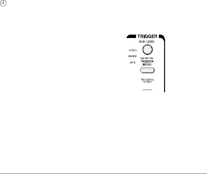
4.Press SET LEVEL TO 50% (see Figure 1)6) to be sure the oscilloscope triggers on the input signal.
SET LEVEL TO 50% Bu on 

Figure 116:0Trigger Controls
TDS 620A, 640A & 644A User Manual |
119 |

Example 1: Displaying a Waveform
Display Elements |
Figure 127 shows the display that results from the instrument reset. There |
||
|
are several important points to observe: |
||
|
The trigger level bar shows that the waveform is triggered at a level near |
||
|
50% of its amplitude (from step 4). |
||
|
The trigger position indicator shows that the trigger position of the |
||
|
waveform is located at the horizontal center of the graticule. |
||
|
The channel reference indicator shows the vertical position of channel 1 |
||
|
with no input signal. This indicator points to the ground level for the |
||
|
channel when its vertical offset is set to 0 V in the vertical menu; when |
||
|
vertical offset is not set to 0 V, it points to the vertical offset level. |
||
|
The trigger readout shows that the digitizing oscilloscope is triggering on |
||
|
channel 1 (Ch1) on a rising edge, and that the trigger level is about |
||
|
200-300 mV. |
||
|
The time base readout shows that the main time base is set to a horizon2 |
||
|
tal scale of 5001 s/div. |
||
|
The channel readout indicates that channel 1 (Ch1) is displayed with DC |
||
|
coupling. ( n AC coupling, ~ appears after the volts/div readout.) The |
||
|
digitizing oscilloscope always displays channel 1 at reset. |
||
|
|
|
|
|
|
|
|
Trigger Level Bar
Trigger Position Indicator
Channel Reference Indicator
Trigger Readout
Time Base Readout
Channel Readout
Figure 1,7:+The Display After Factory Initialization
Right now, the channel, time base, and trigger readouts appear in the grati2 cule area because a menu is displayed. You can press the CLEAR MENU button at any time to remove any menus and to move the readouts below the graticule.
1,10 |
Getting Started |
Adjusting the
Waveform Display
Example 1: Displaying a Waveform
The display shows the probe compensation signal It is a /kHz square wave of approximately 5/V amplitude You can adjust the size and placement of the waveform using the front0panel knobs
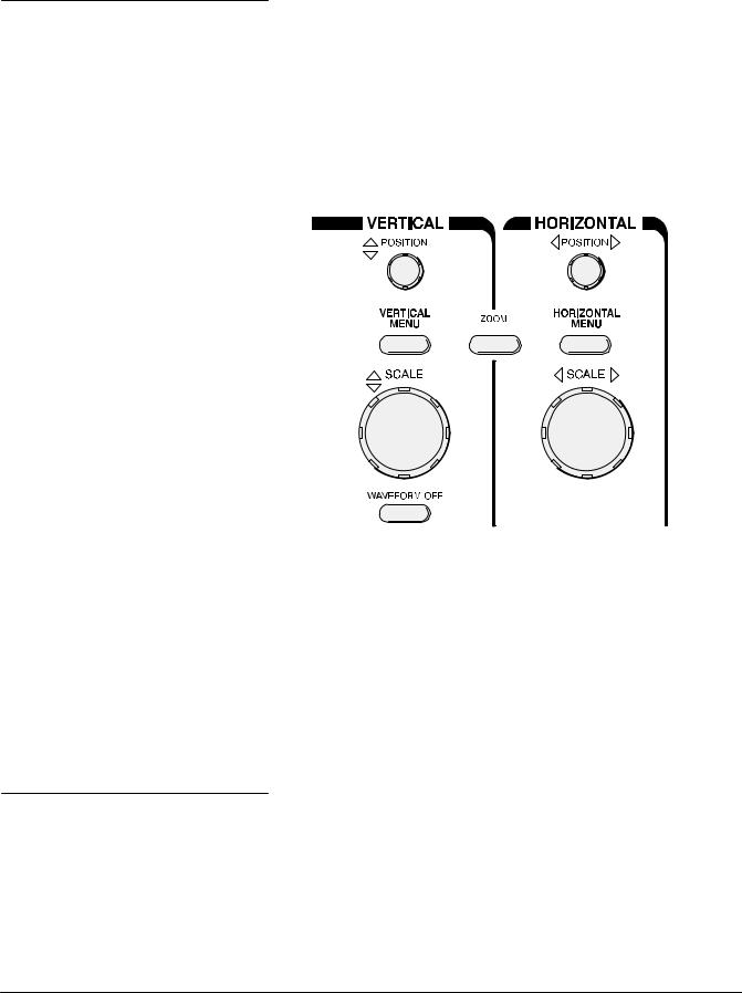
Figure 08 shows the main VERTICAL and HORIZONTAL sections of the front panel Each has SCALE and POSITION knobs
Turn the vertical SCALE knob clockwise Observe the change in the displayed waveform and the channel readout at the bottom of the dis0 play
Figure 138:2The VERTICAL and HORIZONTAL Controls
Using Autoset
Turn the vertical POSITION knob first one direction then the other Observe the change in the displayed waveform Then return the wave0 form to the center of the graticule
Turn the horizontal SCALE knob one click clockwise Observe the time base readout at the bottom of the display The time base should be set to 5 / s div now and you should see two complete waveform cycles on the display
When you first connect a signal to a channel and display it the signal dis0 played may not be scaled and triggered correctly Use the autoset function and you should quickly get a meaningful display
When you reset the digitizing oscilloscope you see a clear stable display of the probe compensation waveform That is because the probe compensa0 tion signal happens to display well at the default settings of the digitizing oscilloscope
TDS 62 A 64 A 644A User Manual |
1311 |
 Loading...