


Programmer Manual
TDS 310, TDS 320 & TDS 350
Two Channel Oscilloscopes
070-8571-04
Use this manual for TDS 310, TDS 320, and TDS 350 oscilloscopes with firmware versions 2.04 and above.
Fifth Edition: December 1994

Copyright Tektronix, Inc. 1993, 1994. All rights reserved.
Tektronix products are covered by U.S. and foreign patents, issued and pending. Information in this publication supercedes that in all previously published material. Specifications and price change privileges reserved.
Printed in the U.S.A.
Tektronix, Inc., P.O. Box 1000, Wilsonville, OR 97070±1000
TEKTRONIX and TEK are registered trademarks of Tektronix, Inc.
QuickC is a trademark of Microsoft, Inc.

WARRANTY
Tektronix warrants that this product will be free from defects in materials and workmanship for a period of three (3) years from the date of shipment. If any such product proves defective during this warranty period, Tektronix, at its option, either will repair the defective product without charge for parts and labor, or will provide a replacement in exchange for the defective product.
In order to obtain service under this warranty, Customer must notify Tektronix of the defect before the expiration of the warranty period and make suitable arrangements for the performance of service. Customer shall be responsible for packaging and shipping the defective product to the service center designated by Tektronix, with shipping charges prepaid. Tektronix shall pay for the return of the product to Customer if the shipment is to a location within the country in which the Tektronix service center is located. Customer shall be responsible for paying all shipping charges, duties, taxes, and any other charges for products returned to any other locations.
This warranty shall not apply to any defect, failure or damage caused by improper use or improper or inadequate maintenance and care. Tektronix shall not be obligated to furnish service under this warranty a) to repair damage resulting from attempts by personnel other than Tektronix representatives to install, repair or service the product; b) to repair damage resulting from improper use or connection to incompatible equipment; or c) to service a product that has been modified or integrated with other products when the effect of such modification or integration increases the time or difficulty of servicing the product.
THIS WARRANTY IS GIVEN BY TEKTRONIX WITH RESPECT TO THIS PRODUCT IN LIEU OF ANY OTHER WARRANTIES, EXPRESSED OR IMPLIED. TEKTRONIX AND ITS VENDORS DISCLAIM ANY IMPLIED WARRANTIES OF MERCHANTABILITY OR FITNESS FOR A PARTICULAR PURPOSE. TEKTRONIX' RESPONSIBILITY TO REPAIR OR REPLACE DEFECTIVE PRODUCTS IS THE SOLE AND EXCLUSIVE REMEDY PROVIDED TO THE CUSTOMER FOR BREACH OF THIS WARRANTY. TEKTRONIX AND ITS VENDORS WILL NOT BE LIABLE FOR ANY INDIRECT, SPECIAL, INCIDENTAL, OR CONSEQUENTIAL DAMAGES IRRESPECTIVE OF WHETHER TEKTRONIX OR THE VENDOR HAS ADVANCE NOTICE OF THE POSSIBILITY OF SUCH DAMAGES.


!)$ ,% ,+1$+10
%$15 2** /5 |
3(( |
/$% "$ |
(4 |
$11(+& 1 /1$#
+2 ) 1/2"12/$ |
8 |
+01 ))(+& '$ -1(,+7 4 ,#2)$ |
8 |
',,0(+& + +1$/% "$ |
8 |
$11(+& - $*,1$ ,**2+(" 1(,+0 |
84 |
5+1 4 +# ,** +#0
,** |
+# 5+1 4 |
8 |
||||||
,** |
+# |
+# 2$/5 1/2"12/$ |
8 |
|||||
)$ /(+& 1'$ 0"()),0",-$ |
84 |
|||||||
,** |
+# +1/5 |
84 |
||||||
,+01/2"1$# +$*,+("0 |
8 |
|||||||
/&2*$+1 5-$0 |
8 |
|||||||
5+1 4 ( &/ *0 |
8 |
|||||||
,** |
+# /,2-0 |
|
8 |
|||||
".2(0(1(,+ ,** |
+#0 |
8 |
||||||
)( |
0 ,** |
+#0 |
8 |
|||||
|
)(!/ |
1(,+ |
+# ( |
&+,01(" ,** +#0 |
8 |
|||
2/0,/ ,** |
+#0 |
8 |
||||||
(0-) 5 ,** |
+#0 |
8 |
||||||
|
/# ,-5 ,** |
+#0 |
|
8 4 |
||||
,/(6,+1 ) ,** |
+#0 |
|
8 4 |
|||||
$ 02/$*$+1 ,** |
+#0 |
8 5 |
||||||
(0"$)) +$,20 ,** |
+#0 |
8 |
||||||
3$ |
+# $" |
)) ,** |
+#0 |
8 8 |
||||
1 |
120 |
+# //,/ ,** |
+#0 |
8 |
||||
/(&&$/ ,** |
+#0 |
8 |
||||||
$/1(" |
) ,** |
+#0 |
8 |
|||||
|
3$%,/* ,** +#0 |
8 |
||||||
,** |
+# $0"/(-1(,+0 |
8 |
||||||
5 /,&/ **$/ +2 ) |
|

Table of Contents
Status Events
Registers . . . . . . . . . . . . . . . . . . . . . . . . . . . . . . . . . . . . . . . . . . . . . . . . |
331 |
Queues . . . . . . . . . . . . . . . . . . . . . . . . . . . . . . . . . . . . . . . . . . . . . . . . . |
335 |
Event Handling Sequence . . . . . . . . . . . . . . . . . . . . . . . . . . . . . . . . |
336 |
Synchronization Methods . . . . . . . . . . . . . . . . . . . . . . . . . . . . . . . . |
337 |
Messages . . . . . . . . . . . . . . . . . . . . . . . . . . . . . . . . . . . . . . . . . . . . . . . |
3313 |
Programming Examples
GPIB Examples . . . . . . . . . . . . . . . . . . . . . . . . . . . . . . . . . . . . . . . . . . |
431 |
RS3232 Examples . . . . . . . . . . . . . . . . . . . . . . . . . . . . . . . . . . . . . . . . |
435 |
Appendices
Appendix A: Character Charts . . . . . . . . . . . . . . . . . . . . . . . . . . . . . . . . |
A31 |
Appendix B: Reserved Words . . . . . . . . . . . . . . . . . . . . . . . . . . . . . . . . |
A33 |
Appendix C: Interface Specifications . . . . . . . . . . . . . . . . . . . . . . . . . . |
A35 |
GPIB Function Subsets . . . . . . . . . . . . . . . . . . . . . . . . . . . . . . . . . . . |
A35 |
Interface Messages . . . . . . . . . . . . . . . . . . . . . . . . . . . . . . . . . . . . . . |
A36 |
Appendix D: Factory Initialization Settings . . . . . . . . . . . . . . . . . . . . . |
A37 |
Glossary and Index
Glossary . . . . . . . . . . . . . . . . . . . . . . . . . . . . . . . . . . . . . . . . . . . . . . . . . . . . |
G31 |
Index . . . . . . . . . . . . . . . . . . . . . . . . . . . . . . . . . . . . . . . . . . . . . . . . . . . . . . . |
I31 |
|
Contents |

List of Figures
.,96* @ ?#-* 311&2) "=28&< "*(8.32 *7(6.'*7 31132 |
|
*77&,* 0*1*287 |
@ |
.,96* @2 ?#-* 311&2)7 "*(8.32 .787 &2) <40&.27 |
|
311&2)7 |
@2 |
.,96* @3 ? "*6:.(* !*59*787 "! 7 63:.)* +36 |
|
:*28 28*66948 6.:*2 63,6&17 |
@2 |
.,96* @ ?#-* .7/7 #-&8 ((314&2= #-.7 &29&0 |
@3 |
.,96* @ ? !"@232 &2) *28632.(7 322*(836 3(&8.327 |
@ |
.,96* @6 ? 3; 83 "8&(/ 322*(8367 |
@ |
.,96* @ ?#=4.(&0 *8;36/ 32+.,96&8.327 |
@6 |
.,96* @ ?"*0*(8.2, 8-* "=78*1 .2 8-* &.2 *29 |
@6 |
.,96* @ ?"*0*(8.2, 8-* ))6*77 .2 8-* 32+.,96&8.32 |
|
".)* *29 |
@ |
.,96* @ ? .2 77.,21*287 3+ 8-* !"@232 322*(836 |
@ |
.,96* @ ?!"@232 &6&1*8*6 "*88.2,7 |
@ |
.,96* @ 2 ?!"@232 &6)(34= *29 |
@ |
.,96* 2@ ? 311&2) *77&,* 0*1*287 |
2@2 |
.,96* 2@2 ? 03(/ 6,91*28 <&140* |
2@ |
.,96* 2@3 ?#=4.(&0 "=28&< .&,6&17 |
2@ |
.,96* 3@ ?#-* "8&2)&6) :*28 "8&897 !*,.78*6 " "! |
3@ |
.,96* 3@2 ?#-* "8&897 =8* !*,.78*6 " ! |
3@2 |
.,96* 3@3 ?#-* *:.(* :*28 "8&897 2&'0* !*,.78*6 " ! |
3@3 |
.,96* 3@ ?#-* :*28 "8&897 2&'0* !*,.78*6 " ! |
3@ |
.,96* 3@ ?#-* "*6:.(* !*59*78 2&'0* !*,.78*6 "! ! |
3@ |
.,96* 3@6 ?"8&897 &2) :*28 &2)0.2, 63(*77 |
3@6 |
.,96* 3@ ? 311&2) 63(*77.2, %.8-398 $7.2, |
|
"=2(-632.>&8.32 |
3@ |
.,96* 3@ ? 63(*77.2, "*59*2(* %.8- "=2(-632.>&8.32 |
3@ |
.,96* @ ? 59.41*28 **)*) 83 !92 8-* &2) !"@232 |
|
<&140* 63,6&17 |
@ |
TDS 310 TDS 320 TDS 350 Programmer Manual |
|

List of Figures
v |
Contents |

List of Tables
T&'l*=1?1:>GPIB &n) RS?232 Comp&r.son . . . . . . . . . . . . . . . . . . . . . . . |
1?3 |
T&'l*=1?2:>RS?232 C&'l*s . . . . . . . . . . . . . . . . . . . . . . . . . . . . . . . . . . . . . |
1?9 |
T&'l*=1?3:>RS?232 Trou'l*s-oot.n, . . . . . . . . . . . . . . . . . . . . . . . . . . . . |
1?13 |
T&'l*=2?1:>BNF Sym'ols &n) M*&n.n,s . . . . . . . . . . . . . . . . . . . . . . . . |
2?1 |
T&'l*=2?2:>Comm&n) M*ss&,* El*m*nts . . . . . . . . . . . . . . . . . . . . . . . |
2?2 |
T&'l*=2?3:>Comp&r.son o+ H*&)*r O++ &n) On R*spons*s . . . . . . . . . |
2?3 |
T&'l*=2?4:>A(qu.s.t.on Comm&n)s . . . . . . . . . . . . . . . . . . . . . . . . . . . . . . |
2?11 |
T&'l*=2?5:>Al.&s Comm&n)s . . . . . . . . . . . . . . . . . . . . . . . . . . . . . . . . . . |
2?11 |
T&'l*=2?6:>C&l.'r&t.on &n) D.&,nost.( Comm&n)s . . . . . . . . . . . . . . . |
2?12 |
T&'l*=2?7:>Cursor Comm&n)s . . . . . . . . . . . . . . . . . . . . . . . . . . . . . . . . . |
2?12 |
T&'l*=2?8:>D.spl&y Comm&n)s . . . . . . . . . . . . . . . . . . . . . . . . . . . . . . . . |
2?13 |
T&'l*=2?9:>H&r) Copy Comm&n)s . . . . . . . . . . . . . . . . . . . . . . . . . . . . . |
2?14 |
T&'l*=2?10:>Hor.zont&l Comm&n)s . . . . . . . . . . . . . . . . . . . . . . . . . . . . |
2?14 |
T&'l*=2?11:>M*&sur*m*nt Comm&n)s . . . . . . . . . . . . . . . . . . . . . . . . . . |
2?16 |
T&'l*=2?12:>M.s(*ll&n*ous Comm&n)s . . . . . . . . . . . . . . . . . . . . . . . . . |
2?17 |
T&'l*=2?13:>S&v* &n) R*(&ll Comm&n)s . . . . . . . . . . . . . . . . . . . . . . . . |
2?18 |
T&'l*=2?14:>St&tus &n) Error Comm&n)s . . . . . . . . . . . . . . . . . . . . . . . |
2?19 |
T&'l*=2?15:>Tr.,,*r Comm&n)s . . . . . . . . . . . . . . . . . . . . . . . . . . . . . . . . |
2?20 |
T&'l*=2?16:>V*rt.(&l Comm&n)s . . . . . . . . . . . . . . . . . . . . . . . . . . . . . . . |
2?20 |
T&'l*=2?17:>W&v*+orm Comm&n)s . . . . . . . . . . . . . . . . . . . . . . . . . . . . . |
2?24 |
T&'l*=2?18:>Comm&n)s t-&t A++*(t BUSY? R*spons* . . . . . . . . . . . . . |
2?41 |
T&'l*=2?19:>O++s*t R&n,*s All C-&nn*ls . . . . . . . . . . . . . . . . . . . . . . . . |
2?46 |
T&'l*=2?20:>DAT& &n) WFMPr* P&r&m*t*r S*tt.n,s . . . . . . . . . . . . . . . |
2?65 |
T&'l*=2?21:>XY Form&t P&.rs . . . . . . . . . . . . . . . . . . . . . . . . . . . . . . . . . . . |
2?76 |
T&'l*=2?22:>Hor.zont&l D*l&y T.m* R*solut.on . . . . . . . . . . . . . . . . . . . . |
2?98 |
T&'l*=2?23:>Comm&n)s t-&t G*n*r&t* &n Op*r&t.on |
|
Compl*t* M*ss&,* . . . . . . . . . . . . . . . . . . . . . . . . . . . . . . . . . . . . . . . |
2?129 |
T&'l*=2?24:>A)).t.on&l WFMPr* Comm&n)s . . . . . . . . . . . . . . . . . . . . . |
2?173 |
T&'l*=3?1:>SESR B.t Fun(t.ons . . . . . . . . . . . . . . . . . . . . . . . . . . . . . . . . . |
3?2 |
T&'l*=3?2:>SBR B.t Fun(t.ons . . . . . . . . . . . . . . . . . . . . . . . . . . . . . . . . . . |
3?3 |
T&'l*=3?3:>No Ev*nt M*ss&,*s . . . . . . . . . . . . . . . . . . . . . . . . . . . . . . . . . |
3?13 |
T&'l*=3?4:>Comm&n) Error M*ss&,*s @ CME B.t 5 . . . . . . . . . . . . . . |
3?13 |
T&'l*=3?5:>Ex*(ut.on Error M*ss&,*s @ EXE B.t 4 . . . . . . . . . . . . . . . |
3?14 |
T&'l*=3?6:>D*v.(* Error M*ss&,*s @ DDE B.t 3 . . . . . . . . . . . . . . . . . . |
3?16 |
T&'l*=3?7:>Syst*m Ev*nt M*ss&,*s . . . . . . . . . . . . . . . . . . . . . . . . . . . . |
3?17 |
T&'l*=3?8:>Ex*(ut.on W&rn.n, M*ss&,*s @ EXE B.t 4 . . . . . . . . . . . . |
3?17 |
T&'l*=3?9:>Int*rn&l W&rn.n, M*ss&,*s . . . . . . . . . . . . . . . . . . . . . . . . . . |
3?18 |
TDS 310 TDS 320 TDS 350 Programmer Manual |
v |

List of Tables
Table)A+1:*The TDS 300 Series Character Set . . . . . . . . . . . . . . . . . . . . |
A+1 |
Table)A+2:*The ASCII & GPIB Code Chart . . . . . . . . . . . . . . . . . . . . . . . |
A+2 |
Table)A+3:*Standard Interface Messages . . . . . . . . . . . . . . . . . . . . . . . . |
A+6 |
Table)A+4:*Factory Initialization Defaults . . . . . . . . . . . . . . . . . . . . . . . . |
A+7 |
v |
Contents |
Safety Summary
Please take a moment to review these safety precautions They are provided for your protection and to prevent damage to the oscilloscope
Symbols and Terms These two terms appear in manuals:
H statements identify conditions or practices that could result in damage to the equipment or other property
H
 statements identify conditions or practices that could result in personal injury or loss of life
These two terms appear on equipment:
HT indicates a personal injury hazard not immediately accessible as one reads the marking or a hazard to property including the equipment itself
HR indicates a personal injury hazard immediately accessible as one reads the marking
This symbol appears in manuals:
Static-Sensitive Devices
These symbols appear on equipment:
DANGER |
Protective |
ATTENTION |
High Voltage |
ground earth |
Refer to |
|
terminal |
manual |
TDS 310 TDS 320 TDS 350 Programmer Manual |
v |

Safety Summary
Specific Precautions Observe all the following precautions to ensure your personal safety and to prevent damage to either the oscilloscope or equipment connected to it.
Power Source
The oscilloscope operates from a power source that will not apply more than 250 VRMS between the supply conductors or between either supply conductor and ground. A protective ground connection, through the grounding conduc, tor in the power cord, is essential for safe system operation.
Grounding the Oscilloscope
The oscilloscope is grounded through the power cord. To avoid electric shock, plug the power cord into a properly wired receptacle with an earth ground connection. Do this before making connections to the input or output termi, nals of the oscilloscope.
Without the protective ground connection, all parts of the oscilloscope are potential shock hazards. This includes knobs and controls that may appear to be insulators.
Use the Proper Power Cord
Use only the power cord and connector specified for your product. Use only a power cord that is in good condition.
Use the Proper Fuse
To avoid fire hazard, use only a fuse that meets all type, voltage, and current specifications.
Do Not Remove Covers or Panels
To avoid personal injury, do not operate the oscilloscope without the panels or covers.
Do Not Operate in Explosive Atmospheres
The oscilloscope provides no explosion protection from static discharges or arcing components. Do not operate the oscilloscope in an atmosphere of explosive gasses.
Electric Overload
Never apply a voltage to a connector on the oscilloscope that is outside the range specified for that connector.
v |
Safety |

Preface
Related Manuals
This is the Programmer Manual for the TDS 310 TDS 320 and TDS 350 Two Channel Oscilloscopes This manual provides information on operating your oscilloscope using the General Purpose Interface Bus GPIB and the RS+232 interface
Following is additional documentation for the oscilloscopes
HTDS 310, TDS 320 & TDS 350 Instruction Manual
HTDS 310, TDS 320 & TDS 350 Reference
HThe XYZs of Analog and Digital Oscilloscopes
TDS 310 TDS 320 TDS 350 Programmer Manual |
x |

Preface
x |
Preface |

Getting Started
This section covers the following topics.
HManual Structure describes the major sections in this manual.
HInstalling the Option 14 Module describes how to install the communica' tions interface.
HChoosing an Interface describes the advantages and disadvantages of GPIB and RS'232 interfaces.
HSetting Up Remote Communications describes setting up for remote control including connecting the oscilloscope and setting the appropriate front panel controls.
Manual Structure |
This manual includes the following sections. |
Syntax and Commands
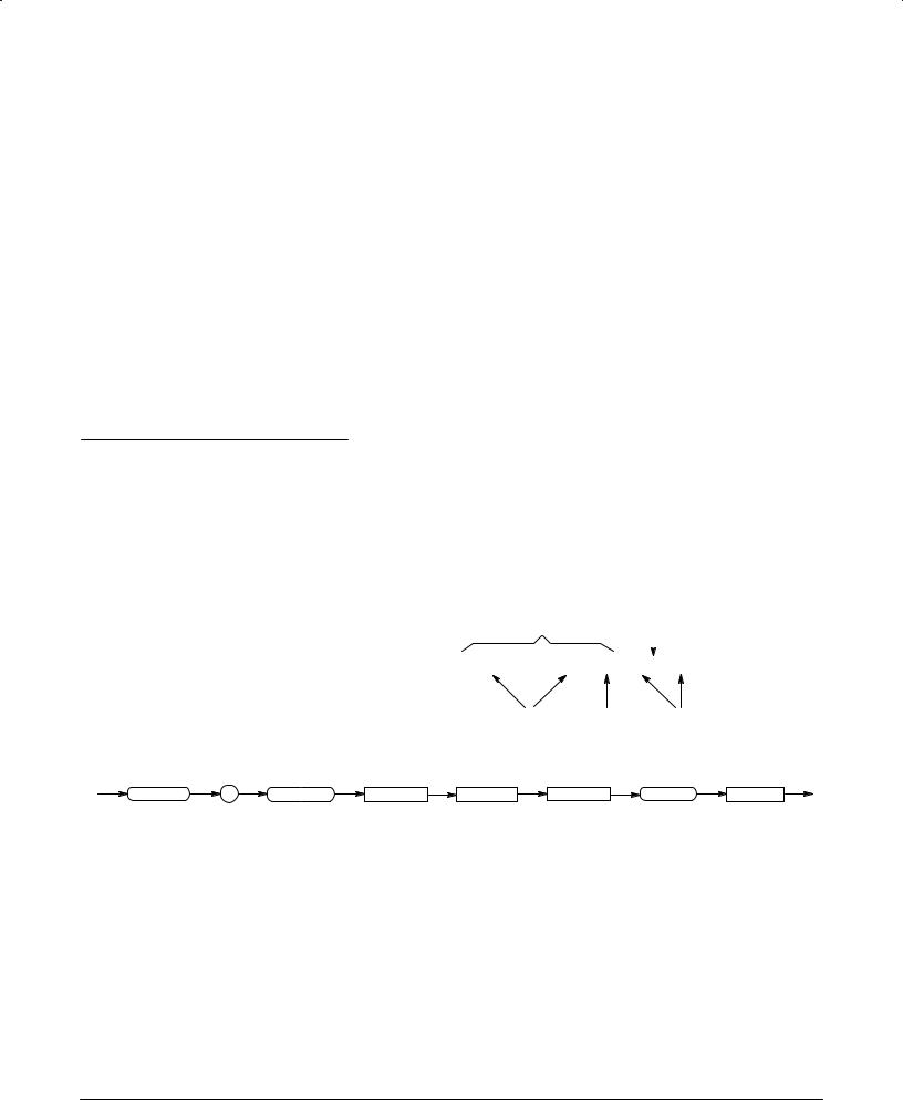
The Syntax and Commands section Section 2 describes the structure of the messages your program sends to the oscilloscope. Figure 1'1 shows a syntax diagram and command parts as described in this section.
Command Parts |
Header |
Comma |
|
|
|
|
|
|
|
|
|
SAVe:WAVEform CH1,REF2
Mnemonics Space Arguments
Syntax Diagram
SAVe |
: |
WAVEform |
<Space> |
<wfm> |
<Comma> |
REF |
<x> |
Figure 1&1:%The Command Syntax Section Describes Common Message Elements
The Syntax and Commands section also describes each command used in the oscilloscope. It explains the syntax of each command and provides examples of how you might use it. The section arranges commands alpha' betically and also provides a list by functional area Figure 1'2 .
TDS 310 TDS 320 TDS 350 Programmer Manual |
1 1 |

Getting Started
|
|
|
|
|
Application Menu Commands |
|
|
|
|
|
|
|
|
ACQuire:NUMACq? (Query Only) |
|
|
||||||||
|
|
|
|
|
|
|
|
|
|
|
|
|
|
|
||||||||||
|
Zoom |
|
|
|
|
|
|
|
|
Zoom |
|
|
|
|
|
|
|
|
|
|
||||
|
|
|
|
|
A |
Alias Commands |
|
|
|
|
|
|
|
S |
|
|
ACQuire:MODe |
|
||||||
|
|
|
|
|
A |
|
|
|
|
|
|
|
|
|
|
G |
|
|
|
|
ACQuire? (Query Only) |
|
||
|
|
A |
Acquisition Commands |
|
|
|
|
|
|
|
S |
|
|
|
||||||||||
|
|
|
|
|
A |
|
|
|
|
|
|
|
|
|
|
|||||||||
|
|
|
|
|
A |
A |
ACQuire:MODe |
|
|
|
|
|
|
E |
|
G |
|
Syntax: . . . |
|
|||||
|
|
|
|
|
A |
A |
|
|
|
|
|
|
|
|
|
|||||||||
|
|
|
|
|
A |
A |
ACQuire:NUMACq? |
|
|
|
|
|
|
|
|
|
E |
|
Group: . . . |
|
||||
|
|
|
|
|
A |
A |
ACQuire:NUMAVg |
|
|
|
|
|
|
|
|
|
|
|
||||||
|
|
|
|
|
|
|
|
|
|
|
|
|
|
|
|
|
|
|
|
|||||
|
|
|
|
|
|
A |
ACQuire:NUMEnv |
|
|
|
|
|
|
|
|
|
|
|
|
Examples: . . . |
|
|||
|
|
|
|
|
|
A |
ACQuire:REPEt |
|
|
|
|
|
|
|
|
|
|
|
|
|
||||
|
|
|
|
|
|
|
|
|
|
|
|
|
|
|
|
|
|
|
|
|
||||
|
|
|
|
|
|
|
ACQuire:STATE |
|
|
|
|
|
|
|
|
|
|
|
|
|
|
|||
|
|
|
|
|
|
|
|
|
|
|
|
|
|
|
|
|
|
|
|
|||||
|
|
|
|
|
|
|
ACQuire:STOPAfter |
|
|
|
|
|
|
|
|
|
|
|
|
|
|
|||
|
|
|
|
|
|
|
|
|
|
|
|
|
|
|
|
|
|
|
|
|||||
|
|
|
|
|
|
|
|
|
|
|
|
|
|
|
|
|
|
|
|
|
|
|
|
|
|
|
|
|
|
|
|
|
|
|
|
|
|
|
|
|
|
|
|
|
|
|
|
|
|
|
|
|
|
|
|
Commands Grouped in 17 Functional |
|
|
|
|
|
|
|
|
Commands Listed Alphabetically |
|
||||||||
and
Areas
Figure 122:1The Commands Section Lists and Explains Commands
Status and Events
The Status and Events section Section 4 starting on page 341 describes how to use GPIB service requests SRQs and various event messages in your programs.
The program requests information from the oscilloscope. The oscilloscope provides information in the form of status and error messages. Figure 143 illustrates the basic operation of this system.
Your program requests status and event reports.
Rear Panel |
Controller |
Oscilloscope sends status and event reports.
Figure 123:1GPIB Service Requests (SRQs) Provide for Event (Interrupt)
Driven Programs
Examples
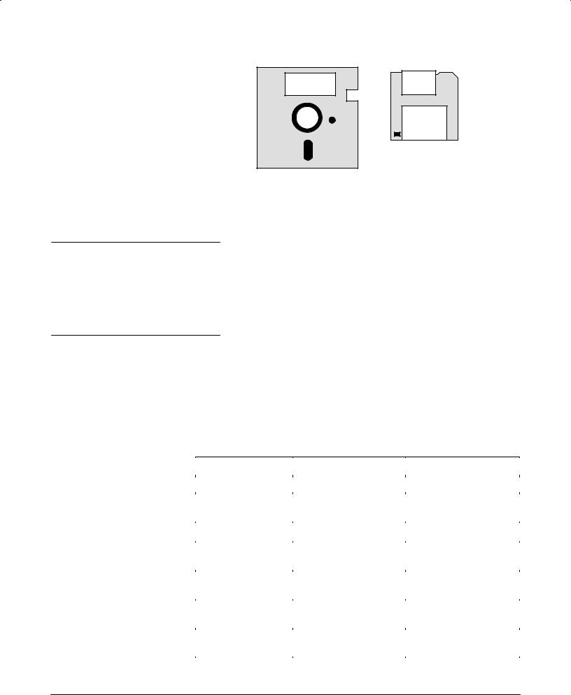
The Programming Examples section starting on page 441 describes example oscilloscope control programs and how to compile them. The disks that come with this manual Figure 144 have an executable and a source code version of each program.
1#2 |
Getting Started |
Getting Started
Example
Programs
Example
Programs
Installing The
Option,14 Module
Figure 1.4:-The Disks That Accompany This Manual
If you received your Option 14 Communications Interface in a separate ship: ment you must install it before remote communications is possible
Use the procedure in your TDS 300 Series TD3F14A I/O Interfaces Upgrade Kit to install your Option 14 module
Choosing an
Interface
Your system hardware may let you choose which interface to use with your system; if so you should consider the comparative advantages and disad: vantages of each interface For example the GPIB interface is an eight bit parallel bus and therefore it offers high:speed data transfers and multiple instrument control In contrast the RS:232 interface is a slower serial data bus for single instrument control but it is easy to connect to and can be used with a low:cost controller Table 1:1 compares the GPIB and RS:232 interface
Table,1.1:-GPIB and RS.232 Comparison
Operating Attribute |
GPIB |
RS.232 |
|
|
|
Cable |
IEEE:488 Std |
9:wire |
|
|
|
Data flow control |
Hardware 3:wire hand: |
Flagging: soft XON |
|
shake |
XOFF hard RTS CTS |
|
|
|
Data format |
8:bit parallel |
8:bit serial |
|
|
|
Interface control |
Operator low:level con: |
None |
|
trol message |
|
|
|
|
Interface messages |
Most IEEE:488 Std |
Device clear via break |
|
|
signal |
|
|
|
Interrupts reported |
Service requests |
None Must be polled for |
|
status and event code |
status |
|
|
|
Message termination |
Hardware EOI software |
Software CR LF or |
Receive |
LF or both |
CRLF or LFCR |
|
|
|
TDS 310 TDS 320 TDS 350 Programmer Manual |
1 3 |
Getting Started
Table+ - :,GPIB and RSComparison (Cont.)
Operating Attribute |
GPIB |
RS- |
|
|
|
Message termination |
Hardware EOI and soft; |
Software CR LF CRLF |
Transmit |
ware LF |
or LFCR |
|
|
|
Timing |
Asynchronous |
Asynchronous |
|
|
|
Transmission path |
|
≤15 meters |
|
2 meters between de; |
|
length |
|
|
|
vices; 20 meters total |
|
|
cabling for GPIB system |
|
|
|
|
Speed |
200 kBytes/sec |
19 200 bits/sec |
|
|
|
System environment |
|
Single terminal point to |
|
Multiple devices 15 |
|
|
|
point connection |
|
|
|
Setting Up Remote
Communications
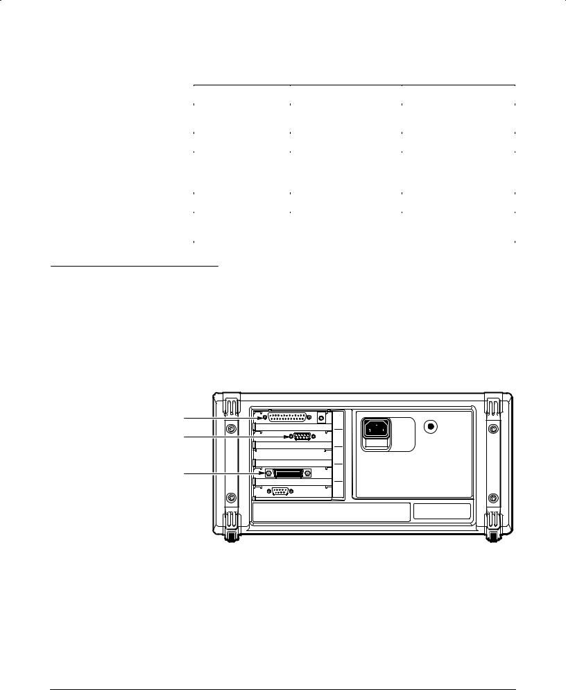
The oscilloscope has GPIB RS;232 and Centronics connectors on its rear panel as shown in Figure 1;5. These connectors have D;type shells. The GPIB connector conforms to IEEE Std. 488.1-1987. The RS;232 connector conforms to ANSI/EIA/TIA Standard 574-1990.
Connecting to a GPIB Device
Attach an IEEE Std. 488.1-1987 GPIB cable to the GPIB connector.
Centronics Connector |
RS 232 Connector |
GPIB Connector |
Figure -5:,GPIB, RS- , and Centronics Connector Locations
If needed you can stack GPIB connectors as shown in Figure 1;6.
GPIB Requirements < Observe these rules when you use your oscillo; scope with a GPIB network:
1 4 |
Getting Started |

Getting Started
HAssign each device on the bus a unique device address; no two devices can share the same device address
HDo not connect more than 15 devices to any one bus
HConnect one device for every 6 feet 2 meters of cable used
HDo not use more than 65 feet 20 meters of cable to connect devices to a bus
HAt least two,thirds of the devices on the network must be turned on while the network is operating
HConnect the devices on the network in a star or linear configuration as shown in Figure 1,7 Do not use loop or parallel configurations
Appendix C: Interface Specifications gives additional information on the GPIB configuration of the oscilloscope
Figure 1'6:&How to Stack GPIB Connectors
TDS 310 TDS 320 TDS 350 Programmer Manual |
1 5 |
Getting Started
GPIB Device |
|
|
GPIB Device |
|
|
|
GPIB Device |
|
|
|
|
|
|
|
|
|
|
|
|
|
|
|
|
|
|
|
|
GPIB Device |
|
|
|
GPIB Device |
|
||
|
|
|
|
|
|
|
|
|
|
|
|
|
|
|
|
|
|
|
GPIB Device |
|
|
|
|
|
GPIB Device |
|
|
|
|
|
|
|
|
|
|
Figure 1+7:*Typical GPIB Network Configurations
Setting the GPIB Parameters ' You need to set the GPIB parameters of the oscilloscope to match the configuration of the bus. Once you have set these parameters, you can control the oscilloscope through the GPIB inter& face.
1.Press the UTILITY button to display the Utility menu.
2.Press the System button in the main menu until it highlights the I/O selection in the pop&up menu.
Figure 1+8:*Selecting the I/O System in the Main Menu
3.Press the Hcp Port button in the main menu; then, if you want hardco& pies to be sent by way of the GPIB port, press GPIB in the side menu.
4.Press the GPIB button in the main menu to display the GPIB configura& tion side menu.
1 6 |
Getting Started |
Getting Started
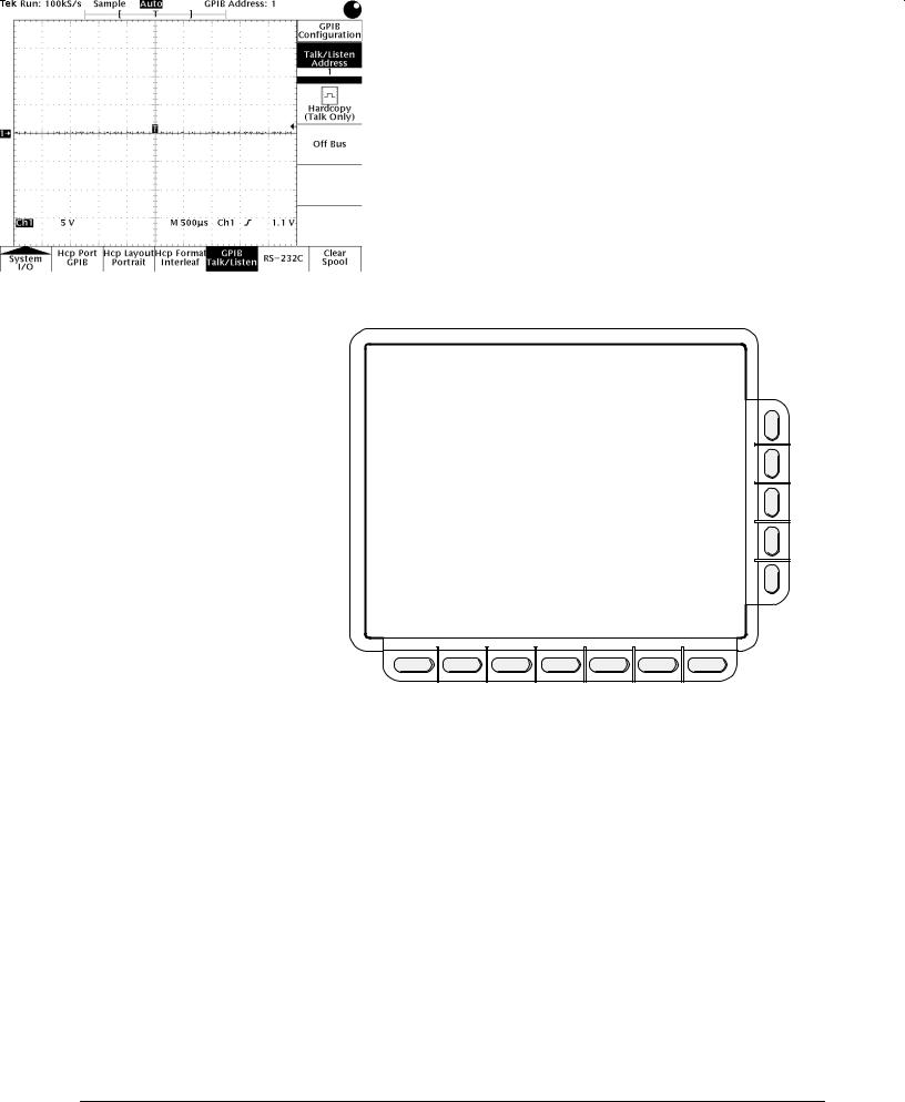
5 Press the Talk/Listen Address side menu button and set the GPIB address using the general purpose knob
The oscilloscope is set up for bidirectional communication with your controller or computer If you wish to isolate the oscilloscope from the bus: press the Off Bus side menu button
If you wish to enter a special mode of operation to communicate directly with non-488 2 hard copy devices press the Hardcopy side menu button The oscilloscope sends hard copy information only when you press the HARD1 COPY button
Figure 19:0Selecting the GPIB Address in the GPIB Configuration
Side Menu
Connecting to an RS1 Device
The RS-232 interface provides a point-to-point connection between two items of equipment such as a computer or terminal and the oscilloscope This section tells how to connect and set up the oscilloscope for communication over the RS-232 interface
RS1 Interface . defines two types of devices: Data Terminal Equipment DTE and Data Communications Equipment DCE
TDS TDS TDS 5 Programmer Manual |
1 7 |

Getting Started
NOTE
Some DTE devices may have female connectors. Also, the RS$232 ports of personal computers may be configured as DCE or DTE devices, with either a 25$pin or a 9$pin connector. Refer to the documentation that accompanies your computer or terminal to determine if it is a DTE or a DCE device.
The oscilloscope is a DTE device. A 93pin D3type shell RS3232 connector is located on the rear panel. In standard usage, a male connector appears on DTE devices, and a female connector appears on DCE devices. A straight3 through female3to3male cable of less than 50 feet is typically used for local DTE3to3DCE connection. Figure 1310 on page 138 shows the oscilloscope 93pin connector with its pin number assignments. When connecting the oscilloscope to another RS3232 device consider these suggestions:
HMany devices require a constant high signal on one or more input pins
HDo not connect the output line of one DTE device to the output line of the other.
HEnsure that the signal ground of the oscilloscope is connected to the signal ground of the external device
HEnsure that the chassis ground of the oscilloscope is connected to the chassis ground of the external device
9-PIN D-SHELL
1 |
No Connection |
|
2 |
Receive Data (RxD) |
|
|
(input) |
|
3 |
Transmit Data (TxD) |
(output) |
4 |
Data Terminal Ready (DTR) |
(output) |
5 |
Signal Ground (GND) |
|
6 |
Data Set Ready (DSR) |
(input) |
7 |
Request to Send (RTS) |
(output) |
8 |
Clear to Send (CTS) |
(input) |
9 |
No Connection |
|
Figure 1 10: Pin Assignments of the RS 232 Connector
In terms of the connector and the way the oscilloscope uses the signal lines, the oscilloscope behaves just like a PC/AT COM port. Table 132 lists cables you can use to connect the oscilloscope to other devices.
1-8 |
Getting Started |

Getting Started
Table+ - :,RS- Cables
Tektronix Part |
Cable Type |
Use |
Number |
|
|
|
|
|
012-1379-00 |
9>p.n +*m&l* 8o 9>p.n |
PC/AT o6 l&p8op |
|
+*m&l* n9ll mo)*m |
|
|
|
|
012-1380-00 |
9>p.n +*m&l* 8o 25>p.n |
Ol) 78yl* PC ;.8- 25>p.n (onn*(8o6 |
|
+*m&l* n9ll mo)*m |
|
|
|
|
012-1298-00 |
9>p.n +*m&l* 8o 25>p.n |
S*6.&l p6.n8*67 79(- &7 &n P |
|
m&l* n9ll mo)*m |
D*7kj*8 &n) S9n ;o6k78&8.on7 |
|
|
|
012-1241-00 |
9>p.n +*m&l* 8o 25>p.n |
T*l*p-on* mo)*m |
|
m&l* mo)*m |
|
|
|
|
Setting RSParameters ? To 7*8 8-* RS>232 p&6&m*8*67 )o 8-* +ollo;.n, 78*p7:
1.P6*77 8-* UTILITY '988on 8o ).7pl&y 8-* U8.l.8y m*n9.
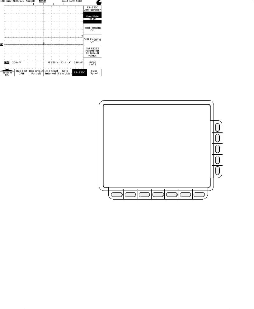
2.P6*77 8-* System m&.n m*n9 '988on 9n8.l I/O .7 7*l*(8*) .n 8-* pop>9p m*n9. T-*n p6*77 8-* RS- m&.n m*n9 '988on 8o ).7pl&y 8-* RS>232C 7.)* m*n9 7** F.,96* 1>11 . Yo9 m&y 7*8 8-* +ollo;.n, p&6&m*8*67:
H B&9) R&8* ? 7*87 8-* )&8& 86&n7m.77.on 6&8*. Yo9 (&n 7*8 6&8*7 o+ 300 600 1200 2400 4800 9600 o6 19200 '&9).
H &6) Fl&,,.n, ? 7*87 -&6) +l&,,.n, RTS/CTS on o6 o++. Fl&,,.n, (on86ol7 8-* +lo; o+ )&8& '*8;**n )*:.(*7. W-*n 'o8- -&6) &n) 7o+8 +l&,,.n, &6* o++ 8-* o7(.llo7(op* )o*7 no8 97* o6 6*(o,n.z* &ny +l&,,.n,. U7* -&6) +l&,,.n, +o6 '.n&6y )&8& 86&n7+*67.
H So+8 Fl&,,.n, ? 7*87 7o+8 +l&,,.n, XON/XOFF on o6 o++. &6) +l&,> ,.n, .7 8-* p6*+*66*) m*8-o) o+ (on86oll.n, 8-* +lo; o+ )&8& '*8;**n )*:.(*7. W-*n 'o8- -&6) &n) 7o+8 +l&,,.n, &6* o++ 8-* o7(.llo7(op* )o*7 no8 97* o6 6*(o,n.z* &ny +l&,,.n,. Yo9 7-o9l) no8 97* 7o+8 +l&,,.n, ;.8- '.n&6y )&8& 86&n7+*6 7.n(* 8-* )&8& m&y (on8&.n XON &n) XOFF (-&6&(8*67. U7* -&6) +l&,,.n, +o6 '.n&6y )&8& 86&n7+*67.
H S*8 RS>232 P&6&m*8*67 8o D*+&9l8 V&l9*7 ? 7*87 )*+&9l8 :&l9*7 +o6 RS>232 p&6&m*8*67 +o6 & l.78 o+ )*+&9l8 7*88.n,7 7** p&,* 2>139 .
H EOL ? 7*87 8-* *n) o+ l.n* 8*6m.n&8o6 7*n8 'y 8-* o7(.llo7(op*. Yo9 (&n 7*8 CR LF CRLF o6 LFCR +o6 mo6* .n+o6m&8.on on l.n* 8*6m.n&> 8o67 7** p&,* 2>142 .
H P&6.8y ? &))7 &n *66o6 (-*(k '.8 n.n8- '.8 8o *&(- (-&6&(8*6. Yo9 (&n 7*8 8-* *66o6 '.8 +o6 *.8-*6 Non* E:*n o6 O)) p&6.8y. W-*n 8-* p&6.8y 7*88.n, .7 o)) o6 *:*n 8-* o7(.llo7(op* ,*n*6&8*7 8-* 7*l*(8*) p&6.8y on o98p98 &n) (-*(k7 .n(om.n, )&8& +o6 8-* 7*l*(8*) p&6.8y. W-*n 8-* p&6.8y 7*88.n, .7 non* 8-*6* .7 no p&6.8y '.8.
H S8op B.87 ? 7*87 8-* n9m'*6 o+ 78op '.87 7*n8 &+8*6 *&(- (-&6&(8*6. Yo9 (&n 7*8 1 o6 2 78op '.87.
TDS TDS TDS 5 Programmer Manual |
1 9 |
Getting Started
HDelay - sets the delay time before responding to a query You can set times from 0 to 60 seconds
3 Press in turn each side menu button until the desired parameter setting is displayed in the side menu or press Set RS 232 Parameters to De fault Values if the default settings are appropriate
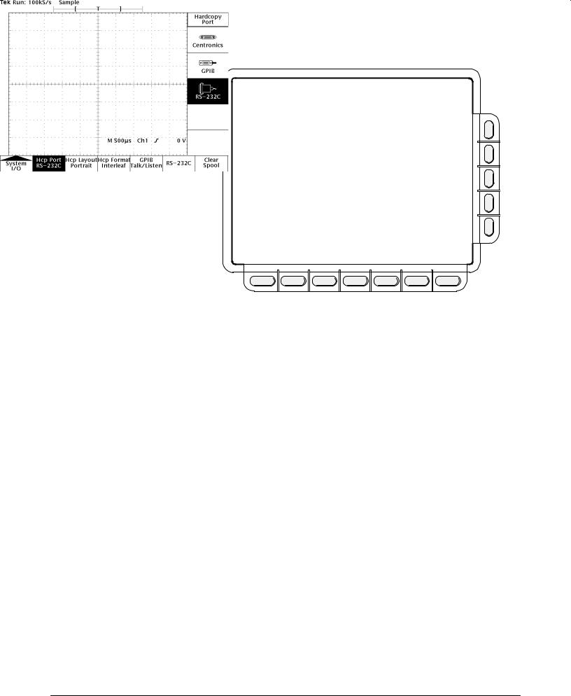
4 Press the Hcp Port main menu button to display the Hard Copy Port side menu Then if you want hardcopies to be sent via the RS,232 port press the RS 232C side menu button to select the RS,232 port as a remote interface port see Figure 1,12
After these parameters are set the RS,232 interface is ready to operate
Figure 1 11: RS 232 Parameter Settings
1 10 |
Getting Started |
Getting Started
Figure 1*12:)RS*232 Hardcopy Menu
RS*232 Conventions
You should be aware of the processing conventions that are specific to the RS0232 interface These conventions pertain to:
HTransferring binary data
HProcessing break signals
HRS0232 I O errors
HService Requests
HHardcopies
When Transferring Binary Data 1 to the oscilloscope via the RS0232 port note the following:
HDo not use binary data transfers with soft flagging unless you can ensure that the data does not contain XON or XOFF characters Using RTS CTShard flagging guarantees correct data transfer
HAll eight bits of binary data contain meaningful information To ensure that all eight bits are received or transmitted an RS0232 device which is connected to the oscilloscope must be configured to receive and transmit eight0bit characters set the RS0232 word length to eight bits
TDS 310 TDS 320 TDS 350 Programmer Manual |
1 11 |

Getting Started
When the Oscilloscope Senses a BREAK Signal ? on the RS>232 port, it returns DCL followed b= the end of line terminator. Internall= the oscilloscope behaves as if a GPIB <DCL> command was received input and output buffers are flushed, and the oscilloscope waits for a new command . BREAK signals do not change oscilloscope settings or stored data and do not inter> rupt front panel operation or nonprogrammable functions.
If a BREAK is sent in the middle of a character stream, a couple of characters immediatel= preceding or following the BREAK ma= be lost. The controller should wait until the DCL and end of line terminator string is received before sending more characters.
RS#232 I/O Errors ? are reported when there is a problem with parit=, framing, or input/output buffer overruns. To report errors, the oscilloscope posts an event code see Status and Events on page 3> . When an error occurs, the oscilloscope discards all input and output and waits for a new command. A count of these errors since last power>on is included in the UTILITY Diag Error Log.
You can use the RS232 Line Snapshot entr= of the error log to help establish an RS>232 connection. The snapshot reports if the oscilloscope is waiting to receive a control Q =es/no , the state of the hardware CTS line high/low , and if characters have been received =es/no . If Waiting For ^Q is Yes, the oscilloscope must receive an XON character before it will transmit an= more data. If CTS is Low and hard flagging is enabled, the oscilloscope will not transmit an= data. If hard flagging is not enabled, =ou should ignore the value of CTS since the oscilloscope ignores it. If Chars Rcvd is Yes, the oscillo> scope has received at least one character since the last power>on.
The RS232 Errors line of the error log lists the number of parit=, framing, and overrun errors since the last power>on.
Service Requests ? are part of the GPIB interface. There is no counterpart for RS>232. However, if =ou want to check the status of each command sent, =ou can append a *STB? quer= after ever= command and read the response string.
Hardcopies ? The Centronics, GPIB, and RS>232 ports are alwa=s active. However, onl= one port at a time can be used for hardcopies. The hardcop= port is selected in the UTILITY I/O menu.
RS#232 Troubleshooting
If the oscilloscope and the personal computer or printer have trouble commu> nicating, use the following steps to correct the problem:
. Verif= that =ou are using the correct RS>232 cable and that it is firml= connected to both the oscilloscope and the correct port on =our personal computer or printer. Verif= that =our printer or the program on the person> al computer is using the correct port. Verif= that the cable is wired correct> l=. Tr= =our program or printer again.
1 12 |
Getting Started |

Getting Started
2 Verify that the settings on both pages of the UTILITY I O RS:232C menu match the settings used by your printer or the program on your personal computer Start by pressing Set RS'232 Parameters to Default Values in the RS:232C menu Then change only those menu items that you know need to be changed like perhaps the baud rate You should not need to change the settings on the second page of the menu because they are standard on most printers and personal computers Try your printer or computer program again
3 If you are trying to generate a hardcopy using the RS:232 port verify that the UTILITY I O Hcp Port is set to RS:232C
4 If you are trying to control the oscilloscope using a personal computer or
|
other computer look at the UTILITY Diag Error Log and examine the |
|
RS232 Line Snapshot and the RS232 Errors Use Table 1:3 to trouble: |
|
shoot your setup The RS232 Line Snapshot and the RS232 Errors will |
|
not change while you are viewing them They are reset when the power is |
|
turned on |
|
Table%1'3:&RS'232 Troubleshooting |
|
|
Symptom |
Possible Cause |
|
|
Your personal computer pro: |
Your RS:232 cable may be wired as a modem instead of a null modem If |
gram tried to send characters to |
you are attempting to use a telephone modem the cable may be wired as a |
the oscilloscope but the oscillo: null modem instead of a modem scope error log displays Chars
Rcvd: No
The oscilloscope shows a non: zero number of Framing errors
There is a baud rate mismatch between the oscilloscope and the personal computer There is an incorrect number of bits sent by the personal comput: er the oscilloscope expects 8 data bits The personal computer may be sending a parity bit when the oscilloscope is expecting no parity
The oscilloscope shows a non: |
There is a parity mismatch between the oscilloscope and the personal com: |
zero number of Parity errors |
puter |
|
|
The oscilloscope shows a non: |
Flagging is not being used by the oscilloscope or the personal computer or |
zero number of Overrun errors |
they are using different types of flagging Ideally hard flagging should be |
|
used unless you are using a telephone modem |
|
|
Transmissions are incomplete |
Flagging is not being used by the oscilloscope or the personal computer or |
or the oscilloscope does not |
they are using different types of flagging Also the end of line terminator |
process all commands from the |
may not match what the personal computer program expects |
personal computer |
|
|
|
The oscilloscope error log dis: |
The oscilloscope is using soft flagging so verify that the personal computer |
plays Waiting for ^Q: Yes |
is also using soft flagging Also verify that the personal computer is not |
|
sending binary data Binary data may contain ^S characters which cause |
|
transmissions to stop |
Soft flagging is being used and transmissions stop
Verify that both the personal computer and the oscilloscope agree that soft flagging is being used Also verify that both the personal computer and the oscilloscope are not sending binary data Binary data may contain ^S char: acters which cause transmissions to stop
TDS 310 TDS 320 TDS 350 Programmer Manual |
1 13 |

Getting Started
Table 1"3:!RS"232 Troubleshooting (Cont )
Symptom |
Possible Cause |
|
|
The oscilloscope error log dis' |
Verify that the RS'232 cable is the recommended cable. Some cables may |
plays CTS: Low, and the oscillo' |
be wired without the CTS or RTS lines which are used by hard flagging. |
scope is using hard flagging. |
Verify that the personal computer program is using CTS/RTS hard flagging. |
|
|
After the personal computer pro' |
Verify that the personal computer program is waiting for and reading the |
gram sends a BREAK, the first |
DCL and end of line terminator response sent by the oscilloscope. |
message fails. |
|
|
|
1 14 |
Getting Started |

 Loading...