


TDS1000B and TDS2000B Series
Digital Storage Oscilloscope
User Manual
Revision A
www.tektronix.com
071-1817-00

Copyright © Tektronix. All rights reserved. Licensed software products are owned by Tektronix or its subsidiaries or suppliers, and are protected by national copyright laws and international treaty provisions.
Tektronix products are covered by U.S. and foreign patents, issued and pending. Information in this publication supersedes that in all previously published material. Specifications and price change privileges reserved.
TEKTRONIX and TEK are registered trademarks of Tektronix, Inc.
OpenChoice™ is a registered trademark of Tektronix, Inc.
PictBridge™ is a registered trademark of the Standard of Camera & Imaging Products Association CIPA DC-001-2003 Digital Photo Solutions for Imaging Devices.
Contacting Tektronix
Tektronix, Inc.
14200 SW Karl Braun Drive
P.O. Box 500
Beaverton, OR 97077
USA
For product information, sales, service, and technical support: In North America, call 1-800-833-9200.
Worldwide, visit www.tektronix.com to find contacts in your area.
TDS1000B and TDS2000B Oscilloscopes
Warranty 18 – Limited Lifetime Warranty
Tektronix warrants to the original end user purchaser (“original purchaser”) of the product listed below that the product will be free from defects in materials and workmanship for the lifetime of the product. As used herein, “lifetime of the product” is defined as a period ending five (5) years after Tektronix discontinues manufacturing the product (as determined by Tektronix), but the warranty period shall be at least ten (10) years from the date of purchase of the product by the original purchaser from Tektronix or an authorized Tektronix distributor. This limited lifetime warranty only applies to the original purchaser and is not transferable. In the event of a warranty claim under the limited lifetime warranty, the purchaser must provide satisfactory evidence of the date of purchase from Tektronix or an authorized Tektronix distributor and that it is the original purchaser. In the event of the sale or other transfer of the product by the original purchaser to a third party within three (3) years of the date of purchase of the product by the original purchaser, the warranty period shall be three (3) years from the date of purchase of the product by the original purchaser from Tektronix or an authorized Tektronix distributor. Probes and other accessories and batteries and fuses are not covered by this warranty.
If the product proves defective during the applicable warranty period, Tektronix, at its option, either will repair the defective product without charge for parts and labor, or will provide a replacement of an equivalent product (as determined by Tektronix) in exchange for the defective product. Parts, modules and replacement products used by Tektronix for warranty work may be new or reconditioned to like new performance. All replaced parts, modules and products become the property of Tektronix.
As used hereafter, “Customer” refers to the person or entity asserting rights under this warranty. In order to obtain service under this warranty, Customer must notify Tektronix of the defect before the expiration of the applicable warranty period and make suitable arrangements for the performance of service. Customer shall be responsible for packaging and shipping the defective product to the service center designated by Tektronix, shipping charges prepaid and with a copy of proof of purchase by the original purchaser. Tektronix shall pay for the return of the product to Customer if the shipment is to a location within the country in which the Tektronix service center is located. Customer shall be responsible for paying all shipping charges, duties, taxes, and any other charges for products returned to any other locations.
This warranty shall not apply to any defect, failure or damage caused by accident, ordinary wear and tear of mechanical components, use outside of the product’s specifications, improper use or improper or inadequate maintenance and care. Tektronix shall not
be obligated to furnish service under this warranty a) to repair damage resulting from attempts by personnel other than Tektronix representatives to install, repair or service the product; b) to repair damage resulting from improper use or connection to incompatible equipment; c) to repair any damage or malfunction caused by the use of non-Tektronix supplies; or d) to service a product that has been modified or integrated with other products when the effect of such modification or integration increases the time or difficulty of servicing the product.
THIS WARRANTY IS GIVEN BY TEKTRONIX WITH RESPECT TO THE PRODUCT IN LIEU OF ANY OTHER WARRANTIES, EXPRESS OR IMPLIED. TEKTRONIX AND ITS VENDORS DISCLAIM ANY IMPLIED WARRANTIES OF
MERCHANTABILITY OR FITNESS FOR A PARTICULAR PURPOSE. TEKTRONIX’ RESPONSIBILITY TO REPAIR OR REPLACE DEFECTIVE PRODUCTS IS THE SOLE AND EXCLUSIVE REMEDY PROVIDED TO THE CUSTOMER FOR BREACH OF THIS WARRANTY. TEKTRONIX AND ITS VENDORS WILL NOT BE LIABLE FOR ANY INDIRECT, SPECIAL, INCIDENTAL, OR CONSEQUENTIAL DAMAGES IRRESPECTIVE OF WHETHER TEKTRONIX OR THE VENDOR HAS ADVANCE NOTICE OF THE POSSIBILITY OF SUCH DAMAGES.
P2220 Probe
Warranty 2
Tektronix warrants that this product will be free from defects in materials and workmanship for a period of one (1) year from the date of shipment. If any such product proves defective during this warranty period, Tektronix, at its option, either will repair the defective product without charge for parts and labor, or will provide a replacement in exchange for the defective product. Parts, modules and replacement products used by Tektronix for warranty work may be new or reconditioned to like new performance. All replaced parts, modules and products become the property of Tektronix.
In order to obtain service under this warranty, Customer must notify Tektronix of the defect before the expiration of the warranty period and make suitable arrangements for the performance of service. Customer shall be responsible for packaging and shipping the defective product to the service center designated by Tektronix, with shipping charges prepaid. Tektronix shall pay for the return of the product to Customer if the shipment is to a location within the country in which the Tektronix service center is located. Customer shall be responsible for paying all shipping charges, duties, taxes, and any other charges for products returned to any other locations.
This warranty shall not apply to any defect, failure or damage caused by improper use or improper or inadequate maintenance and care. Tektronix shall not be obligated to furnish service under this warranty a) to repair damage resulting from attempts by personnel other than Tektronix representatives to install, repair or service the product; b) to repair damage resulting from improper use or connection to incompatible equipment; c) to repair any damage or malfunction caused by the use of non-Tektronix supplies; or d) to service a product that has been modified or integrated with other products when the effect of such modification or integration increases the time or difficulty of servicing the product.
THIS WARRANTY IS GIVEN BY TEKTRONIX WITH RESPECT TO THE PRODUCT IN LIEU OF ANY OTHER WARRANTIES, EXPRESS OR IMPLIED. TEKTRONIX AND ITS VENDORS DISCLAIM ANY IMPLIED WARRANTIES OF MERCHANTABILITY OR FITNESS FOR A PARTICULAR PURPOSE. TEKTRONIX’ RESPONSIBILITY TO REPAIR OR REPLACE DEFECTIVE PRODUCTS IS THE SOLE AND EXCLUSIVE REMEDY PROVIDED TO THE CUSTOMER FOR BREACH OF THIS WARRANTY. TEKTRONIX AND ITS VENDORS WILL NOT BE LIABLE FOR ANY INDIRECT, SPECIAL, INCIDENTAL, OR CONSEQUENTIAL DAMAGES IRRESPECTIVE OF WHETHER TEKTRONIX OR THE VENDOR HAS ADVANCE NOTICE OF THE POSSIBILITY OF SUCH DAMAGES.

Table of Contents |
|
General Safety Summary ............................................... |
iv |
Environmental Considerations ........................................ |
vii |
Preface.................................................................... |
ix |
Help System ......................................................... |
x |
Firmware Updates Through the Internet ......................... |
xi |
Conventions........................................................ |
xii |
Getting Started............................................................ |
1 |
General Features..................................................... |
1 |
Installation ........................................................... |
3 |
Functional Check.................................................... |
4 |
Probe Safety ......................................................... |
5 |
Voltage Probe Check Wizard ....................................... |
5 |
Manual Probe Compensation....................................... |
7 |
Probe Attenuation Setting .......................................... |
8 |
Current Probe Scaling............................................... |
8 |
Self Calibration ...................................................... |
9 |
Operating Basics........................................................ |
11 |
Display Area ....................................................... |
12 |
Using the Menu System .......................................... |
15 |
Vertical Controls................................................... |
16 |
Horizontal Controls ............................................... |
17 |
Trigger Controls ................................................... |
18 |
Menu and Control Buttons ....................................... |
19 |
Input Connectors .................................................. |
22 |
Other Front-Panel Items .......................................... |
23 |
Understanding Oscilloscope Functions ............................... |
25 |
Setting Up the Oscilloscope ...................................... |
25 |
Triggering .......................................................... |
26 |
Acquiring Signals ................................................. |
29 |
Scaling and Positioning Waveforms ............................. |
30 |
Taking Measurements............................................. |
34 |
TDS1000B/2000B Series Oscilloscope User Manual |
i |

Table of Contents |
|
Application Examples.................................................. |
37 |
Taking Simple Measurements .................................... |
38 |
Using Autorange to Examine a Series of Test Points........... |
43 |
Taking Cursor Measurements .................................... |
44 |
Analyzing Signal Detail .......................................... |
48 |
Capturing a Single-Shot Signal .................................. |
51 |
Measuring Propagation Delay.................................... |
53 |
Triggering on a Specific Pulse Width............................ |
54 |
Triggering on a Video Signal..................................... |
56 |
Analyzing a Differential Communication Signal ............... |
61 |
Viewing Impedance Changes in a Network ..................... |
63 |
Math FFT................................................................ |
67 |
Setting Up the Time-Domain Waveform ........................ |
67 |
Displaying the FFT Spectrum .................................... |
69 |
Selecting an FFT Window ........................................ |
70 |
Magnifying and Positioning an FFT Spectrum ................. |
74 |
Measuring an FFT Spectrum Using Cursors .................... |
75 |
USB Flash Drive and Device Ports ................................... |
77 |
USB Flash Drive Port ............................................. |
77 |
File Management Conventions................................... |
79 |
Saving and Recalling Files With a USB Flash Drive........... |
80 |
Using the Save Function of the PRINT Front Panel Button ... |
82 |
USB Device Port .................................................. |
85 |
Installing the PC Communications Software on a PC.......... |
85 |
Connecting to a PC................................................ |
86 |
Connecting to a GPIB System.................................... |
89 |
Command Entry ................................................... |
89 |
Connecting to a Printer ........................................... |
90 |
Printing a Screen Image .......................................... |
90 |
Reference................................................................ |
93 |
Acquire............................................................. |
93 |
Autorange .......................................................... |
96 |
Autoset ............................................................. |
98 |
Cursor ............................................................. |
102 |
Default Setup ..................................................... |
103 |
ii |
TDS1000B/2000B Series Oscilloscope User Manual |

Table of Contents
Display ............................................................ 103
Help ............................................................... 107
Horizontal......................................................... 107
Math ............................................................... 109
Measure ........................................................... 111
Print ............................................................... 112
Probe Check ...................................................... 113
Ref Menu.......................................................... 114
Save/Recall ....................................................... 114
Trigger Controls .................................................. 121
Utility.............................................................. 128
Vertical Controls.................................................. 132
Appendix A: Specifications........................................... 135
Oscilloscope Specifications...................................... 135
Oscilloscope Certifications and Compliances.................. 148
P2220 Probe Specifications...................................... 153
Appendix B: Accessories ............................................. 157
Appendix C: Cleaning ................................................ 161
General Care ...................................................... 161
Cleaning........................................................... 161
Appendix D: Default Setup........................................... 163
Appendix E: Font Licenses ........................................... 167
Index
TDS1000B/2000B Series Oscilloscope User Manual |
iii |

General Safety Summary
General Safety Summary
Review the following safety precautions to avoid injury and prevent damage to this product or any products connected to it.
To avoid potential hazards, use this product only as specified.
Only qualified personnel should perform service procedures.
To Avoid Fire or Personal Injury
Use Proper Power Cord. Use only the power cord specified for this product and certified for the country of use.
Connect and Disconnect Properly. Connect the probe output to the measurement instrument before connecting the probe to the circuit under test. Connect the probe reference lead to the circuit under test before connecting the probe input. Disconnect the probe input and the probe reference lead from the circuit under test before disconnecting the probe from the measurement instrument.
Ground the Product. This product is grounded through the grounding conductor of the power cord. To avoid electric shock, the grounding conductor must be connected to earth ground. Before making connections to the input or output terminals of the product, ensure that the product is properly grounded.
Observe All Terminal Ratings. To avoid fire or shock hazard, observe all ratings and markings on the product. Consult the product manual for further ratings information before making connections to the product.
Connect the probe reference lead to earth ground only.
Do not apply a potential to any terminal, including the common terminal, that exceeds the maximum rating of that terminal.
Power Disconnect. The power switch disconnects the product from the power source. See instructions for the location. Do not block the power switch; it must remain accessible to the user at all times.
Do Not Operate Without Covers. Do not operate this product with covers or panels removed.
iv |
TDS1000B/2000B Series Oscilloscope User Manual |
General Safety Summary
Do Not Operate With Suspected Failures. If you suspect that there is damage to this product, have it inspected by qualified service personnel.
Avoid Exposed Circuitry. Do not touch exposed connections and components when power is present.
Do Not Operate in Wet/Damp Conditions.
Do Not Operate in an Explosive Atmosphere.
Keep Product Surfaces Clean and Dry.
Provide Proper Ventilation. Refer to the manual’s installation instructions for details on installing the product so it has proper ventilation.
TDS1000B/2000B Series Oscilloscope User Manual |
v |
General Safety Summary
Terms in this Manual
These terms may appear in this manual:
WARNING. Warning statements identify conditions or practices that could result in injury or loss of life.
CAUTION. Caution statements identify conditions or practices that could result in damage to this product or other property.
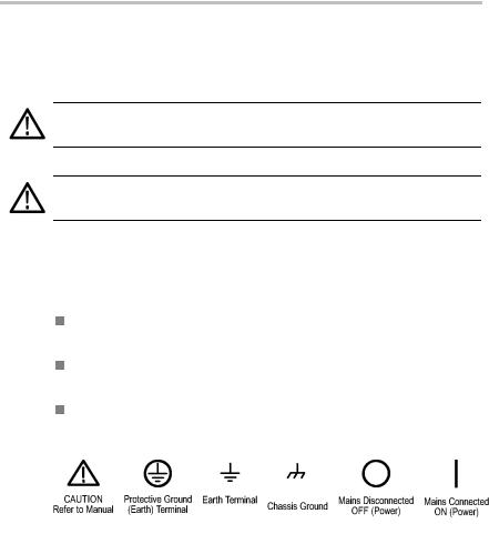
Symbols and Terms on the Product
These terms may appear on the product:
DANGER indicates an injury hazard immediately accessible as you read the marking.
WARNING indicates an injury hazard not immediately accessible as you read the marking.
CAUTION indicates a hazard to property including the product.
The following symbol(s) may appear on the product:
vi |
TDS1000B/2000B Series Oscilloscope User Manual |

Environmental Considerations
This section provides information about the environmental impact of the product.
Product End-of-Life Handling
Observe the following guidelines when recycling an instrument or component:
Equipment Recycling. Production of this equipment required the extraction and use of natural resources. The equipment may contain substances that could be harmful to the environment or human health if improperly handled at the product’s end of life. In order to avoid release of such substances into the environment and to reduce the use of natural resources, we encourage you to recycle this product in an appropriate system that will ensure that most of the materials are reused or recycled appropriately.
The symbol shown below indicates that this product complies with the European Union’s requirements according to Directive 2002/96/EC on waste electrical and electronic equipment (WEEE). For information about recycling options, check the Support/Service section of the Tektronix Web site (www.tektronix.com).
Mercury Notification. This product uses an LCD backlight lamp that contains mercury. Disposal may be regulated due to environmental considerations. Please contact your local authorities or, within the United States, the Electronics Industries Alliance (www.eiae.org) for disposal or recycling information.
TDS1000B/2000B Series Oscilloscope User Manual |
vii |

Environmental Considerations
Restriction of Hazardous Substances
This product has been classified as Monitoring and Control equipment, and is outside the scope of the 2002/95/EC RoHS Directive. This product is known to contain lead, cadmium, mercury, and hexavalent chromium.
viii |
TDS1000B/2000B Series Oscilloscope User Manual |

Preface
Preface
This manual contains operating information for the TDS1000B and TDS2000B Series Digital Storage Oscilloscopes. The manual consists of the following chapters:
The Getting Started chapter briefly describes features of the oscilloscope and provides installation instructions.
The Operating Basics chapter covers operating principles of the oscilloscopes.
The Understanding Oscilloscope Functions chapter describes basic operations and functions of an oscilloscope: setting up the oscilloscope, triggering, acquiring data, scaling and positioning waveforms, and taking measurements.
The Application Examples chapter provides examples on how to solve a variety of measurement problems.
The Math FFT chapter describes how to use the Math Fast Fourier Transform function to convert a time-domain signal into its frequency components (spectrum).
The USB Flash Drive and Device Ports chapter describes how to use the USB Flash Drive port and how to connect the oscilloscope to printers and computers through the USB Device port.
The Reference chapter describes the selections or available range of values for each option.
The Appendix A: Specifications chapter includes electrical, environmental, and physical specifications for the oscilloscope and the P2220 probe, as well as certifications and compliances.
The Appendix B: Accessories chapter briefly describes standard and optional accessories.
The Appendix C: Cleaning chapter describes how to take care of the oscilloscope.
The Appendix D: Default Setup chapter contains a list of the menus and controls with the default (factory) settings that are recalled when you push the DEFAULT SETUP front-panel button.
TDS1000B/2000B Series Oscilloscope User Manual |
ix |

Preface
The Appendix E: Font Licenses chapter provides the licenses to use specific Asian fonts.
Help System
The oscilloscope has a Help system with topics that cover all the features of the oscilloscope. You can use the Help system to display several kinds of information:
General information about understanding and using the oscilloscope, such as Using the Menu System.
Information about specific menus and controls, such as the Vertical Position Control.
Advice about problems you may face while using an oscilloscope, such as Reducing Noise.
The Help system provides several ways to find the information you need: context-sensitive help, hyperlinks, and an index.
Context-Sensitive Help
The oscilloscope displays information about the last menu displayed on the screen when you push the HELP front-panel button. When viewing help topics, an LED lights next to the multipurpose knob to indicate that the knob is active. If the topic uses more than one page, turn the multipurpose knob to move from page to page within the topic.
Hyperlinks
Most of the help topics contain phrases marked with angle brackets, such as <Autoset>. These are links to other topics. Turn the multipurpose knob to move the highlight from one link to another. Push the Show Topic option button to display the topic corresponding to the highlighted link. Push the Back option button to return to the previous topic.
x |
TDS1000B/2000B Series Oscilloscope User Manual |

Preface
Index
Push the front-panel HELP button, then push the Index option button. Push the Page Up or Page Down option buttons until you find the index page that contains the topic you want to view. Turn the multipurpose knob to highlight a help topic. Push the Show Topic option button to display the topic.
NOTE. Push the Exit option button or any menu button to remove the Help text from the screen and return to displaying waveforms.
Firmware Updates Through the Internet
If a newer version of firmware becomes available, you can use the Internet and a USB flash drive to update your oscilloscope. If you do not have access to the Internet, contact Tektronix for information on update procedures.
To update the firmware from the Internet, follow these steps:
1.Push the UTILITY ► System Status option, and write down the firmware version number of the oscilloscope.
2.From your computer, access the www.tektronix.com web site and check if a newer version of oscilloscope firmware is available.
3.If there is a newer version of firmware, download the firmware file from the web page.
You may need to unzip the downloaded file.
4.Copy the TDS1K2KB.TEK firmware file to the root folder of a USB flash drive.
5.Insert the USB flash drive into the USB Flash Drive port on the front of the oscilloscope.
6.From your oscilloscope, push the UTILITY ► File Utilities ► - more - page 2 of 2 ► Update Firmware option button.
It takes several minutes to update the firmware.
Your oscilloscope will prompt you to press a button when the firmware update is complete. You must not remove the USB flash drive, or power off the oscilloscope until the firmware update is complete.
TDS1000B/2000B Series Oscilloscope User Manual |
xi |
Preface
Conventions
This manual uses the following conventions:
Front-panel buttons, knobs and connectors appear in all uppercase letters. For example: HELP, PRINT.
Menu options appear with the first letter of each word in upper case. For example: Peak Detect, Window Zone.
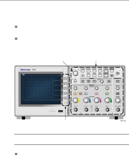
|
Front-panel buttons and knob labels |
Multipurpose knob |
— All upper case |
Option buttons — First letter of each word on screen is upper case
NOTE. Option buttons may also be called screen buttons, side-menu buttons, bezel buttons, or soft keys.
The ► delimiter separates a series of button pushes. For example,
UTILITY ► Options ► Set Date and Time means that you push the UTILITY front-panel button, then push the Options option button, and then push the Set Date and Time option button. Multiple pushes of an option button may be required to select the desired option.
xii |
TDS1000B/2000B Series Oscilloscope User Manual |

Getting Started
TDS1000B and TDS2000B Series Digital Storage Oscilloscopes are small, lightweight, benchtop oscilloscope you can use to take ground-referenced measurements.
This chapter describes how to do the following tasks:
Install your product
Perform a brief functional check
Perform a probe check and compensate probes
Match your probe attenuation factor
Use the self calibration routine
NOTE. You can select a language to display on the screen when you power on the oscilloscope. At any time, you can also access the UTILITY ► Language option to select a language.
General Features
The next table and list describe the general features.
Model |
Channels |
Bandwidth |
Sample rate |
Display |
TDS1001B |
2 |
40 MHz |
500 MS/s |
Monochrome |
TDS1002B |
2 |
60 MHz |
1.0 GS/s |
Monochrome |
TDS1012B |
2 |
100 MHz |
1.0 GS/s |
Monochrome |
TDS2002B |
2 |
60 MHz |
1.0 GS/s |
Color |
TDS2004B |
4 |
60 MHz |
1.0 GS/s |
Color |
TDS2012B |
2 |
100 MHz |
1.0 GS/s |
Color |
TDS2014B |
4 |
100 MHz |
1.0 GS/s |
Color |
TDS2022B |
2 |
200 MHz |
2.0 GS/s |
Color |
TDS2024B |
4 |
200 MHz |
2.0 GS/s |
Color |
TDS1000B/2000B Series Oscilloscope User Manual |
1 |

Getting Started
Context-sensitive help system
Color or monochrome LCD display
Selectable 20 MHz bandwidth limit
2500 point record length for each channel Autoset
Autoranging
Probe Check Wizard
Setup and waveform storage
USB Flash Drive port for file storage
Direct printing to any PictBridge compatible printer
PC communications through the USB Device port with OpenChoice PC Communications software
Connect to a GPIB controller through an optional TEK-USB-488 adapter
Cursors with readouts
Trigger frequency readout
Eleven automatic measurements
Waveform averaging and peak detection
Dual time base
Math functions: +, -, and × operations
Math Fast Fourier Transform (FFT)
Pulse Width trigger capability
Video trigger capability with line-selectable triggering External trigger
Variable persistence display
User interface and help topics in ten languages
2 |
TDS1000B/2000B Series Oscilloscope User Manual |
Getting Started
Installation
Power Cord
Use only the power cord provided with your oscilloscope. Appendix B: Accessories lists the standard and the optional accessories.
Power Source
Use a power source that delivers 90 to 264 VACRMS, 45 to 66 Hz. If you have a 400 Hz power source, it must deliver 90 to 132 VACRMS, 360 to 440 Hz.
Security Loop
Use a standard laptop computer security lock, or thread a security cable through the built-in cable channel to secure your oscilloscope to your location.
Security cable channel |
Security lock hole |
Power cord |
Ventilation
NOTE. The oscilloscope cools by convection. Keep two inches clear on the sides and top of the product to allow adequate air flow.
TDS1000B/2000B Series Oscilloscope User Manual |
3 |
Getting Started
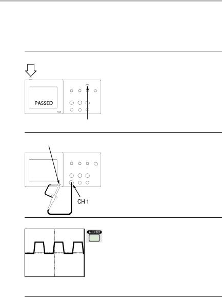
Functional Check
Perform this functional check to verify that your oscilloscope is operating correctly.
ON/OFF button
1. Power on the oscilloscope.
Push the DEFAULT SETUP button.
The default Probe option attenuation setting is 10X.
DEFAULT SETUP button
PROBE COMP
2. Set the switch to 10X on the P2220 probe and connect the probe to channel 1 on the oscilloscope. To do this, align the slot in the probe connector with the key on the CH 1 BNC, push to connect, and twist to the right to lock the probe in place.
Connect the probe tip and reference lead to the PROBE COMP terminals.
3. Push the AUTOSET button. Within a few seconds, you should see a
square wave in the display of about 5V peak-to-peak at 1 kHz.
Push the CH1 MENU button on the front panel twice to remove channel 1, push the CH 2 MENU button to display channel 2, and repeat steps 2 and 3. For 4-channel models, repeat for CH 3 and CH 4.
4 |
TDS1000B/2000B Series Oscilloscope User Manual |

Getting Started
Probe Safety
Check and observe probe ratings before using probes.
A guard around the P2220 probe body provides a finger barrier for protection from electric shock.
Finger guard
WARNING. To avoid electric shock when using the probe, keep fingers behind the guard on the probe body.
To avoid electric shock while using the probe, do not touch metallic portions of the probe head while it is connected to a voltage source.
Connect the probe to the oscilloscope, and connect the ground terminal to ground before you take any measurements.
Voltage Probe Check Wizard
You can use the Probe Check Wizard to verify that a voltage probe is operating properly. The wizard does not support current probes.
The wizard helps you adjust the compensation for voltage probes (usually with a screw on the probe body or probe connector) and set the factor for the Attenuation option for each channel, such as in the CH 1 MENU ► Probe ► Voltage ► Attenuation option.
TDS1000B/2000B Series Oscilloscope User Manual |
5 |

Getting Started
You should use the Probe Check Wizard each time you connect a voltage probe to an input channel.
To use the Probe Check Wizard, push the PROBE CHECK button. If the voltage probe is connected properly, compensated properly, and the Attenuation option in the oscilloscope VERTICAL menu is set to match the probe, the oscilloscope displays a PASSED message at the bottom of the screen. Otherwise, the oscilloscope displays directions on the screen to guide you in correcting these problems.
NOTE. The Probe Check Wizard is useful for 1X, 10X, 20X, 50X, and 100X probes. It is not useful for 500X or 1000X probes, or for probes connected to the EXT TRIG BNC.
NOTE. When the process is complete, the Probe Check Wizard restores the oscilloscope settings (other than the Probe option) to what they were before you pushed the PROBE CHECK button.
To compensate a probe that you plan to use with the EXT TRIG input, follow these steps:
1.Connect the probe to any input channel BNC, such as to CH 1.
2.Push the PROBE CHECK button and follow the directions on the screen.
3.After you verify that the probe functions and is compensated properly, connect the probe to the EXT TRIG BNC.
6 |
TDS1000B/2000B Series Oscilloscope User Manual |
Getting Started
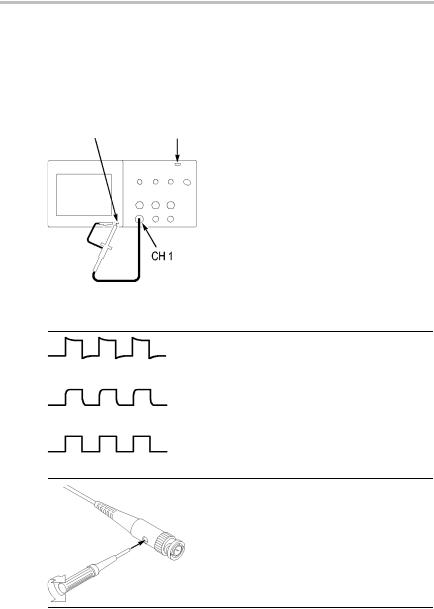
Manual Probe Compensation
As an alternative method to the Probe Check Wizard, you can manually perform this adjustment to match your probe to the input channel.
PROBE |
AUTOSET |
COMP |
button |
1.Push the CH 1 MENU ► Probe ► Voltage ► Attenuation option and select 10X. Set the switch to 10X on the P2220 probe and connect the probe to channel 1 on the oscilloscope. If you use the probe hook-tip, ensure a proper connection by firmly inserting the tip onto the probe.
2.Attach the probe tip to the PROBE COMP ~5V@1kHz terminal and the reference lead to the PROBE COMP chassis terminal. Display the channel, and then push the AUTOSET button.
3.Check the shape of the displayed waveform.
Overcompensated
Undercompensated
Compensated correctly
4.If necessary, adjust your probe. The P2220 probe is shown.
Repeat as necessary.
TDS1000B/2000B Series Oscilloscope User Manual |
7 |

Getting Started
Probe Attenuation Setting
Probes are available with various attenuation factors which affect the vertical scale of the signal. The Probe Check Wizard verifies that the attenuation factor in the oscilloscope matches the probe.
As an alternative method to Probe Check, you can manually select the factor that matches the attenuation of your probe. For example, to match a probe set to 10X connected to CH 1, push the CH 1 MENU ► Probe
► Voltage ► Attenuation option, and select 10X.
NOTE. The default setting for the Attenuation option is 10X.
If you change the Attenuation switch on the P2220 probe, you also need to change the oscilloscope Attenuation option to match. Switch settings are 1X and 10X.
Attenuation switch
NOTE. When the Attenuation switch is set to 1X, the P2220 probe limits the bandwidth of the oscilloscope to 6 MHz. To use the full bandwidth of the oscilloscope, be sure to set the switch to 10X.
Current Probe Scaling
Current probes provide a voltage signal proportional to the current. You need to set the oscilloscope to match the scale of your current probe. The default scale is 10 A/V.
For example, to set the scale for a current probe connected to CH 1, push the CH 1 MENU ► Probe ► Current ► Scale option, and select an appropriate value.
8 |
TDS1000B/2000B Series Oscilloscope User Manual |

Getting Started
Self Calibration
The self calibration routine lets you optimize the oscilloscope signal path for maximum measurement accuracy. You can run the routine at any time but you should always run the routine if the ambient temperature changes by 5 °C (9 °F) or more. The routine takes about two minutes.
For accurate calibration, power on the oscilloscope and wait twenty minutes to ensure it is warmed up.
To compensate the signal path, disconnect any probes or cables from the input connectors. Then, access the UTILITY ► Do Self Cal option, and follow the directions on the screen.
TDS1000B/2000B Series Oscilloscope User Manual |
9 |

Getting Started
10 |
TDS1000B/2000B Series Oscilloscope User Manual |

Operating Basics
The front panel is divided into easy-to-use functional areas. This chapter provides you with a quick overview of the controls and the information displayed on the screen.
2-channel model
4-channel model
TDS1000B/2000B Series Oscilloscope User Manual |
11 |

Operating Basics
Display Area
In addition to displaying waveforms, the display is filled with many details about the waveform and the oscilloscope control settings.
NOTE. For details on displaying the FFT function, (See page 69, Displaying the FFT Spectrum.)
1.Icon display shows acquisition mode.
Sample mode
Peak detect mode
Average mode
12 |
TDS1000B/2000B Series Oscilloscope User Manual |
 Loading...