

Page 1

•
•
•
- Data Brochure
D 481
tekmarNet®4 User Switch 481
1
Information
Brochure
Choose controls
to match
application
2
Application
Brochure
Design your
mechanical
applications
3
Rough In
Wiring
Rough-in
wiring
instructions
4
Wiring
Brochure
Wiring and
installation of
specific control
5
Data
Brochure
Control settings
and sequence of
operation
Introduction
The User Switch 481 has 3 programmable buttons that allow
users to easily change the operating scene or allow users
to enable / disable tN4 setpoint controls on a tN4 system.
Multiple User Switches are required if more than 3 scenes
or setpoint enable / disables are desired.
The 481 has 3 output relay contacts that allow for connection
to alarm systems or paging systems to alert service personnel.
The output relay contacts can also be used to indicate the
scene of the tN4 system to an automation system.
Features
• tN4 Compatible
• 3 User buttons
• 3 Programmable Output
Relay Contacts
- Output for Critical Alert
- Output for Non Critical
Alert
- Output for Scenes
- Output for Enable /
Disable Signal
User
Button
1
User
Button
2
User
Button
3
07/09
6
Job
Decora cover plate not included
Record
Record settings &
wiring details for
future reference
1 of 12 © 2009 D 481 - 07/09
Page 2

Table of Contents
Table of Contents .............................. 2
User Interface ................................... 2
Sequence of Operation ..................... 2
Three User Buttons ..................... 2
Programming the User Buttons .... 4
Output Relay Contacts and
Applications Using Multiple
480 & 481 Together ..........................9
Cleaning the User Switch .............. 10
User Button Label Template ........... 10
Error Messages .............................. 11
Warranty ......................................... 12
DIP Switches .................................... 7
User Interface
The User Switch has a total of 5 buttons.
User Buttons 1, 2, and 3 allow for users to select the operation of the tN4 system.
Buttons A and B allow the installer to program the operation of User Buttons 1, 2,
and 3.
BUTTON
A
User
Button
1
User
Button
2
User
Button
3
BUTTON
B
Factory Defaults:
User Button 1
Scene = 1
Label = Normal
User Button 2
Scene = 3
Label = Unoccupied
User Button 3
Scene = 2
Label = Away
Sequence of Operation
Three User Buttons
The User Switch provides users with a simple interface to change the operating
scene of the tN4 system or provide an enable / disable to tN4 setpoint controls. The
481 has 3 User Buttons and 3 output relay contacts.
© 2009 D 481 - 07/09 2 of 12
Page 3

The 3 User Buttons provide the ability to:
1) Select a scene for the tN4 system
The User Buttons allow users to select the scene of the tN4 system. Each of the 3
User Buttons is programmed by the installer to select a particular scene on the tN4
system. The temperature of each tN4 thermostat in the system is pre-programmed
by the installer for each of the scenes. This allows users to change the temperature
of all the thermostats using a single button.
tN4 thermostats and tN4 setpoint controls must have Scenes turned to “On” in order
to respond to scene changes on the User Switch.
When a User Button is pressed, the green LED under that button turns on and
remains on until a new scene is selected, or the time for the selected temporary
scene expires.
When the current selected scene on the tN4 network is the same as the scene that
the User Button is programmed for, the button turns green.
When a selected scene is “On” and that User button is pressed again, the scene is
changed based on the following table:
Current Scene
Press the
Same Button
New Scene
Perm Scene 1 No Change
Perm Scene 2 - Away Selects Scene 1
Perm Scene 3 - Unoccupied Selects Scene 1
Perm Scene 4 Selects Scene 1
Perm Scene 5 Selects Scene 1
Tmpy Scene 6 - Occupied Selects previous perm scene
Tmpy S c ene 7 Selects previous perm scene
Tmpy S c ene 8 Selects previous perm scene
Application Examples:
Allows residential users to change the scene to 2 (Away) while going on vacation,
or select an occupied scene while entertaining guests.
Allows commercial users a simple way to allow staff to override the night setback
/ setup schedule on the tN4 system.
3 of 12 © 2009 D 481 - 07/09
Page 4
2) Provide a setpoint device enable
Each of the 3 User Buttons can be programmed to enable or disable one or more
tN4 setpoint controls on the tN4 bus. The installer programs a setpoint device enable
number for one of the User Buttons. In turn, the installer programs a tN4 setpoint
control with the same setpoint device enable number. This allows users to enable
or disable a tN4 setpoint control by pressing a single button. Multiple tN4 setpoint
controls can be enabled or disabled from the same User Switch button.
The tN4 setpoint control operates for the “Occupied Time” or until the User Button
is pressed once again to cancel the operation. The User Button is green when the
tN4 setpoint device is in operation. Should the tN4 setpoint control be unable to
operate, the button turns red for 5 seconds and then the button light is turned off.
See the tN4 Setpoint Control Data Brochure for more information on the setpoint
control operation.
Application Examples:
A user can remotely enable a tN4 setpoint control to heat a hot tub or sauna.
A user can remotely enable a tN4 setpoint control to heat a garage or
workshop.
3) Disabled Button
The User Button can be disabled so that it does not function when pressed.
In certain cases, the disabled button can be used to close the corresponding relay
contact. See the “Button Operation” section for more information.
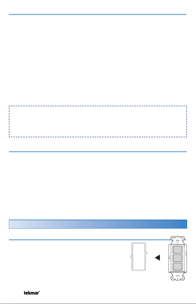
Programming the User Buttons
STEP 1
Remove the plastic trim bezel.
© 2009 D 481 - 07/09 4 of 12
Button
Button
Button
User
1
User
2
User
3
Page 5

STEP 2
•
•
•
User
Press button “A” once using a blunt object to begin
programming mode.
Each of the 3 User Buttons will begin to flash to indicate
the current program setting:
• Red flashes indicate the User Button is programmed
PRESS
BUTTON
A
Button
Button
Button
1
User
2
User
3
to select a scene. The number of flashes in a row
indicate the scene number.
• Green flashes indicate the User Button is programmed to enable or disable a
tN4 setpoint control. The number of flashes in a row indicate the setpoint device
enable number.
• Orange indicates the User Button has been disabled.
STEP 3
Press and hold down the User Button until the button changes to the color of
operation that is desired and then release the button.
Red = Scene
Green = tN4 Setpoint Control Enable / Disable
Orange = Disabled Button
STEP 4
(Scene Operation, Red Flashes)
Press the User Button the number of times equal to the desired scene.
Press “User”
Button
Scene Red Light Flash
Sequence
1 Time 1 1 Red, Off, Repeat
2 Times 2 (Away) 2 Red, Off, Repeat
3 Times 3 (Unoccupied) 3 Red, Off, Repeat
4 Times 4 4 Red, Off, Repeat
5 Times 5 5 Red, Off, Repeat
6 Times 6 (3 hr. Temporary Occupied) 6 Red, Off, Repeat
7 Times 7 (4 hr. Temporary) 7 Red, Off, Repeat
8 Times 8 (8 hr. Temporary) 8 Red, Off, Repeat
5 of 12 © 2009 D 481 - 07/09
Page 6

STEP 4 (Continued)
(Setpoint Device Enable, Green Flashes)
Press the User Button the number of times equal to the desired setpoint device
enable number.
Press “User” Button Setpoint Enable Green Light Flash Sequence
1 Time 1 1 Green, Off, Repeat
2 Times 2 2 Green, Off, Repeat
3 Times 3 3 Green, Off, Repeat
4 Times 4 4 Green, Off, Repeat
5 Times 5 5 Green, Off, Repeat
6 Times 6 6 Green, Off, Repeat
7 Times 7 7 Green, Off, Repeat
8 Times 8 8 Green, Off, Repeat
9 Times 9 9 Green, Off, Repeat
10 Times 10 10 Green, Off, Repeat
11 Times 11 11 Green, Off, Repeat
12 Times 12 12 Green, Off, Repeat
STEP 5
Press button “B” to finalize the User Button setting and
exit the programming mode.
Note: To return to Step 2 without saving the setting,
press button “A”.
STEP 6
Repeat steps 2 through 5 to program each User
Button.
STEP 7
Included with the User Switch are labels to identify
the operation of each User Button. Each label has a
description on it. Choose the label with the appropriate
description for each button.
A template has been included on Page 10 to create
your own labels.
Insert the label into the slot located under the right
hand side of each User Button.
Repeat for each User Button.
© 2009 D 481 - 07/09 6 of 12
Button
Button
Button
User
1
User
2
User
3
PRESS
BUTTON
B
User
Button
1
User
Button
2
User
Button
3
Page 7

STEP 8
1
ON
OFF
123
Replace the trim bezel.
Output Relay Contacts and DIP Switches
The functionality of the 3 dry relay contacts
on the User Switch 481 are determined by
the settings of DIP switches 1, 2 and 3. Dip
switches 1 and 2 select the mode of operation
for relay outputs.
1014-01
Relays
Rly
Pwr
123
tN4 User Switch 481
Three Outputs
Power: 24 V ± 10% 50/60 Hz 4 VA
Relays: 30 V (ac) 1A
Use at least 194°F
(90°C) conductors
For product
instructions
see brochure
CRtN4
OFF
1
tN4
Meets Class B:
Canada
• Canadian ICES
• FCC Part 15
ON
123
User
Button
1
User
Button
2
User
Button
3
DIP Switches
Permanent or Momentary Contact Closure
DIP switch 3 = OFF (Permanent)
DIP switch 3 = ON (Momentary)
The output relay contacts can close momentarily for 5 seconds and then re-open or
the relay contacts can close permanently. Use DIP switch 3 to select either Momentary
or Permanent. Momentary closure is often used in alarm systems. Permanent is
the factory default setting.
Alert and Scene Status
DIP switch 1 = OFF
DIP switch 2 = OFF
DIP switch 3 = Permanent or Momentary
Relay contact 1 closes to provide an alert when there is an error message present
on the tN4 system.
Relay contact 2 closes while the scene is set to Away (Scene 2).
Relay contact 3 closes while the scene is set to Scene 3.
Application Examples:
The relay contacts can connect to a third party alarm system or automation system
to provide the status of the tN4 system.
Relay contact 2 can connect to a non-tN4 snow melt control (664, 665, 667) to
provide an Idle Demand. The snow melt control Idle temperature is set to OFF.
While the tN4 system is in Away (scene 2), the snow melt control is prevented
from entering the melting operation.
7 of 12 © 2009 D 481 - 07/09
OFF
OFF
ON
ON
Page 8

OFF
Critical and Non-Critical Alert Levels
ON
DIP switch 1 = ON
DIP switch 2 = OFF
DIP switch 3 = Permanent or Momentary
Relay contact 1 closes while a non-critical error message is present on the tN4
system. A non-critical error allows the heating system to continue to operate.
Relay contact 2 closes while a critical error message is present on the tN4 system.
The critical errors are:
1) Adjust EEPROM error on any device.
2 Boiler supply sensor open or short circuit.
3) Mix supply sensor open or short circuit.
4) A thermostat has no air or floor temperature sensor reading.
Relay contact 3 is not used.
Application Example:
The relay contacts can connect to a third party paging device that, when activated,
pages a service technician when a critical error message is present.
Button Operation
OFF
ON
DIP switch 1 = OFF
DIP switch 2 = ON
DIP switch 3 = Permanent or Momentary
Each relay contact is synchronized with the corresponding User Button. When a
button is pressed or the scene is changed to the User Button’s programmed scene,
the relay contact closes.
Application Examples:
The relay contacts can connect to a third party automation system to indicate that
one of the User Buttons has been activated.
The User Button can be programmed to the “disabled” button operation. When the
User Button is pressed, the light turns green and the corresponding output relay
contact can activate lighting, security cameras, alarms or power a melt demand
on a non-tN4 snow melt control (664, 665, 667) to manually start snow melting.
OFF
Scene Signal
ON
DIP switch 1 = ON
DIP switch 2 = ON
DIP switch 3 = Permanent or Momentary
The relay contacts operate in combinations in order to communicate the current tN4
scene to third party devices. The contacts operate according to the following table:
© 2009 D 481 - 07/09 8 of 12
Page 9

Scene 1 2 3 4 5 6 7 8
Contact 1
Contact 2
Contact 3
Application Example:
The relay contact can connect to a third party automation system to indicate the
current tN4 scene.
Off On Off On Off On Off On
Off Off On On Off Off On On
Off Off Off Off On On On On
Scene
Signals
Applications Using Multiple 480 and 481 Together
Multiple User Switches 480 and 481 can be used together when:
1) Applications require more than 3 User Buttons.
2) Applications require both input demands and output relay contacts.
3) User Switches with the same functionality are required at different locations.
Each tN4 bus cannot exceed 24 devices. Devices include Thermostats, Setpoint
Controls, Mixing Expansion Modules, and User Switches.
When using multiple User Switches at the same location, they can be installed
adjacent to each other in the same switch box.
Applications requiring more than 3 User Buttons
When more than 3 User Buttons are required, two or more User Switches can be
located next to each other in a double switch box. Each button can be programmed
to either select a scene or provide a setpoint enable.
Application Example:
Applications that select more than three scenes or setpoint device enables will
require two or more User Switches.
Applications with both input demands and output relay contacts
Applications that require input demands and output relay contacts require a 480
and a 481. The 480 provides the input demands and the 481 provides the output
contacts.
Application Example:
A third party telephone switch device allows a user to change the scene from 1
to 2 (Away) through the demand input on the 480. Should a critical or non-critical
error occur on the tN4 system, a 481 can close an alert contact to allow a third
party telephone switch to page a service technician.
9 of 12 © 2009 D 481 - 07/09
Page 10
User Switches with the same functionality at different locations
There may be applications where there are two or more User Switches installed
in a building. Each of the User Switch User Buttons can be programmed with the
same functionality. When an User Button is pressed, User Buttons with the same
functionality will all light green at the same time.
Application Example:
A User Switch is installed in the garage and another User Switch is installed in
the master bedroom.
Cleaning the User Switch
The User Switch’s exterior can be cleaned using a damp cloth. Moisten the cloth
with water and wring out prior to wiping the device. Do not use solvents or cleaning
solutions.
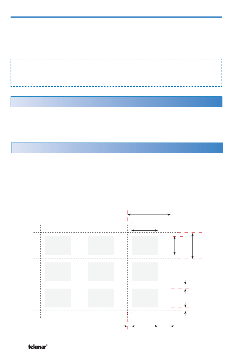
User Button Label Template
1) Download the User Switch Data Brochure PDF file D481.pdf from the
Downloadable Literature Section on our tekmar website:
http://www.tekmarcontrols.com to your computer.
2) Click on the grey area (text field) and type the label description.
3) Print this page onto transparency film. Ensure the correct transparency film type
is used for either laser printers or bubble-jet printers.
© 2009 D 481 - 07/09 10 of 12
0.10”
(2.6 mm)
0.62” (15.7 mm)
1.03” (26.2 mm)
0.31”
(7.9 mm)
0.44”
(11.0 mm)
0.62”
(15.8 mm)
0.10”
(2.4 mm)
0.10”
(2.4 mm)
Page 11
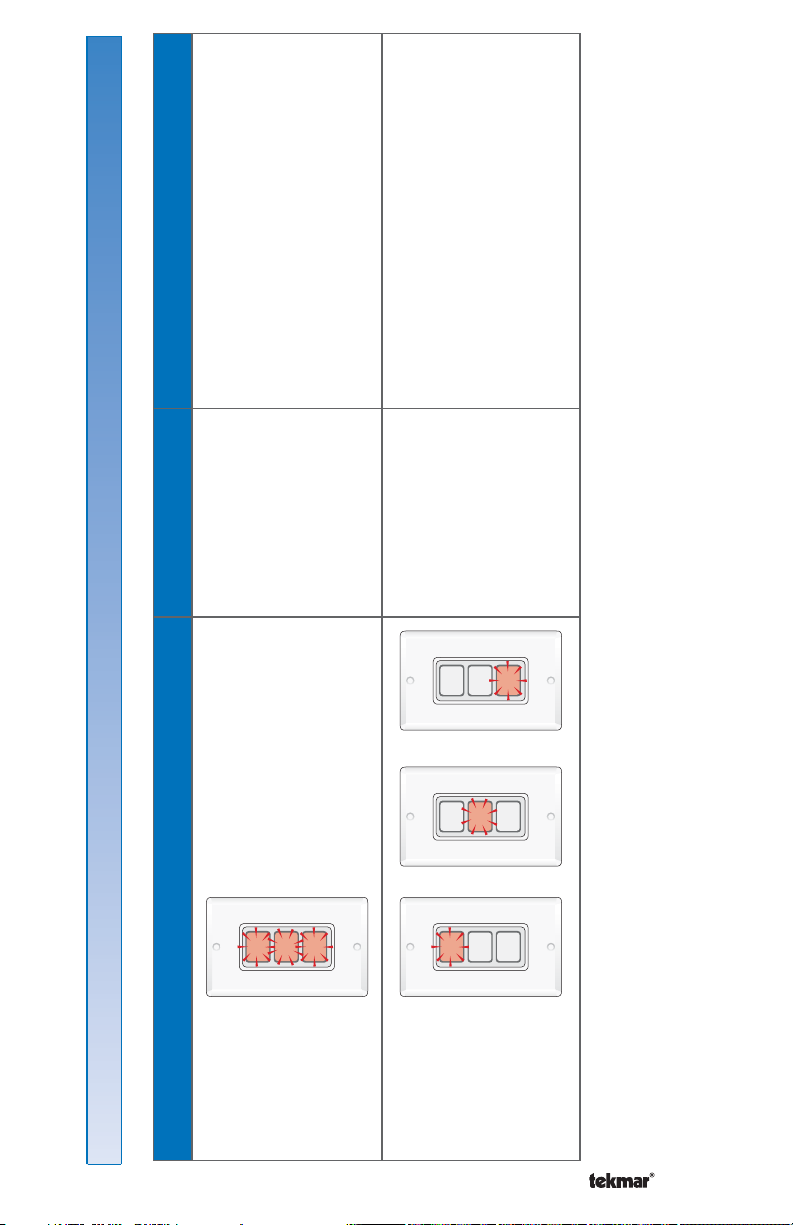
•
loose wire connections.
•
•
•
• Check tN4 and common wires for
• Ensure the tN4 controls have power.• • Check R and C wires for correct
User Switch
disconnected from
tN4 bus.
1
2
User
Button
3
User
User
Button
Button
polarity.
power and is connected to the tN4
• Ensure the setpoint device has
The User Button
is configured for
1
User
Button
1
User
Button
bus.
• Ensure the setpoint device enable
setpoint device
enable operation
and there is no
2
3
User
User
Button
Button
2
3
User
User
Button
Button
number of the User Button and of
the tN4 setpoint control match.
response from the
tN4 setpoint control.
or or
1
2
User
Button
3
User
User
Button
Button
Error Messages
Error Messages
Symptom Cause Corrective Action
3 Buttons
Flashing Red
1 Button
Flashing Red
11 of 12 © 2009 D 481 - 07/09
Page 12

Limited Warranty and Product Return Procedure
Limited Warranty The li ability of tekmar u nder this warranty is li mit ed. The Purchas er, by taking r eceipt of
any tekmar product (“Product”), acknowledges the terms of the Limited Warranty in effect at the time of
such Product sale and acknowledges that it has read and understands same.
The tekmar Limited Warranty to the Purchaser on the Products sold hereunder is a manufacturer’s pass-through
warranty which the Purchaser is authorized to pass through to its customers. Under the Limited Warranty, each
tekmar Product is warranted against defects in workmanship and materials if the Product is installed and used
in compliance with tekmar’s instructions, ordinary wear and tear excepted. The pass-through warranty period is
for a period of twenty-four (24) months from the production date if the Product is not installed during that period,
or twelve (12) months from the documented date of installation if installed within twenty-four (24) months from
the production date.
The liability of tekmar under the Limited Warranty shall be limited to, at tekmar’s sole discretion: the cost of parts
and labor provided by tekmar to repair defects in materials and / or workmanship of the defective product; or to the
exchange of the defective product for a warranty replac ement product; or to the granting of credit limited to the
original cost of the defective product, and such repair, exchange or credit shall be the sole remedy available from
tekmar, and, without limiting the foregoing in any way, tekmar is not responsible, in contract, tort or strict product
liability, for any other losses, costs, expenses, inconveniences, or damages, whether direct, indirect, special, secondar y, incidental or c onsequential, arising from ownership or use of the product, or from defects in workmanship
or materials, inc luding any liability for fundamental breach of contract.
The pass-through Limited Warranty applies only to those defective Products returned to tekmar during the warranty period. This Limited Warranty does not cover the cost of the par ts or labor to remove or transport the defective Product, or to reinstall the repaired or replacement Product, all such costs and expenses being subject to
Purchaser’s agreement and warrant y with its customers.
Any representations or warranties about the Products made by Purchaser to its customers which are different from
or in excess of the tekmar Limited Warranty are the Purchaser’s sole responsibility and obligation. Purchaser shall
indemnify and hold tekmar harmless from and against any and all claims, liabilities and damages of any kind or
nature which arise out of or are related to any such representations or warranties by Purchaser to its customers.
The pass-through Limited Warranty does not apply if the returned Produc t has been damaged by negligence by
persons other than tekmar, accident, fire, Act of God, abuse or misuse; or has been damaged by modifications,
alterations or attachments made subsequent to purchase which have not been authorized by tekmar; or if the
Product was not installed in compliance with tekmar’s instruc tions and / or the local codes and ordinances; or if due
to defective installation of the Product; or if the Product was not used in compliance with tek mar’s instructions.
THIS WARRANTY IS IN LIEU OF ALL OTHER WARRANTIES, EXPRESS OR IMPLIED, WHICH THE GOVERNING
LAW ALLOWS PARTIES TO CONTRACTUALLY EXCLUDE, INCLUDING, WITHOUT LIMITATION, IMPLIED WARRANTIES OF MERCHANTABILITY AND FITNESS FOR A PARTICULAR PURPOSE, DURABILITY OR DESCRIPTION OF THE PRODUCT, ITS NON-INFRINGEMENT OF ANY RELEVANT PATENTS OR TRADEMARKS, AND
ITS COMPLIANCE WITH OR NON-VIOLATION OF ANY APPLICABLE ENVIRONMENTAL, HEALTH OR SAFETY
LEGISLATION; THE TERM OF ANY OTHER WARRANT Y NOT HEREBY CONTRACTUALLY EXCLUDED IS LIMITED SUCH THAT IT SHALL NOT EXTEND BEYOND TWENTY-FOUR (24) MONTHS FROM THE PRODUCTION
DATE, TO THE EXTENT THAT SUCH LIMITATION IS ALLOWED BY THE GOVERNING LAW.
Product Warranty Return Procedure All Products that are believed to have defec ts in workmanship or materials must be returned, together with a written description of the defect, to the tekmar Representative assigned to
the territory in which such Product is located. If tekmar receives an inquiry from someone other than a tekmar
Representative, including an inquiry from Purchaser (if not a tekmar Representative) or Purchaser’s customers,
regarding a potential warrant y claim, tekmar’s sole obligation shall be to provide the address and other contact
information regarding the appropriate Representative.
tekmar Control Systems Ltd., Canada
tekmar Control Systems, Inc., U.S .A.
Head O ffic e: 5100 Sil ver Sta r Road
Vernon, B.C. Can ada V1B 3K4
(250) 54 5-7749 Fax. (2 50) 54 5- 065 0
Web Site: w ww.te kmar contr ols.c om
All specifications are subject
to change without notice
Product design, soft ware and literature
are Copyright © 2009 by:
tekmar Control Systems Ltd. and tekmar
Control Systems, Inc.
12 of 12 D 481 - 07/09.
 Loading...