

Page 1
- Data Brochure
tekmarNet®4 Thermostat 544
D 544
07/08
1
Information
Brochure
Choose controls
to match
application
2
Application
Brochure
Design your
mechanical
applications
3
Rough In
Rough-in
instructions
Wiring
wiring
4
Wiring
Brochure
Wiring and
installation of
specific control
5
Data
Brochure
Control settings
and sequence of
operation
6
Job
Record
Record settings &
wiring details for
future reference
Introduction
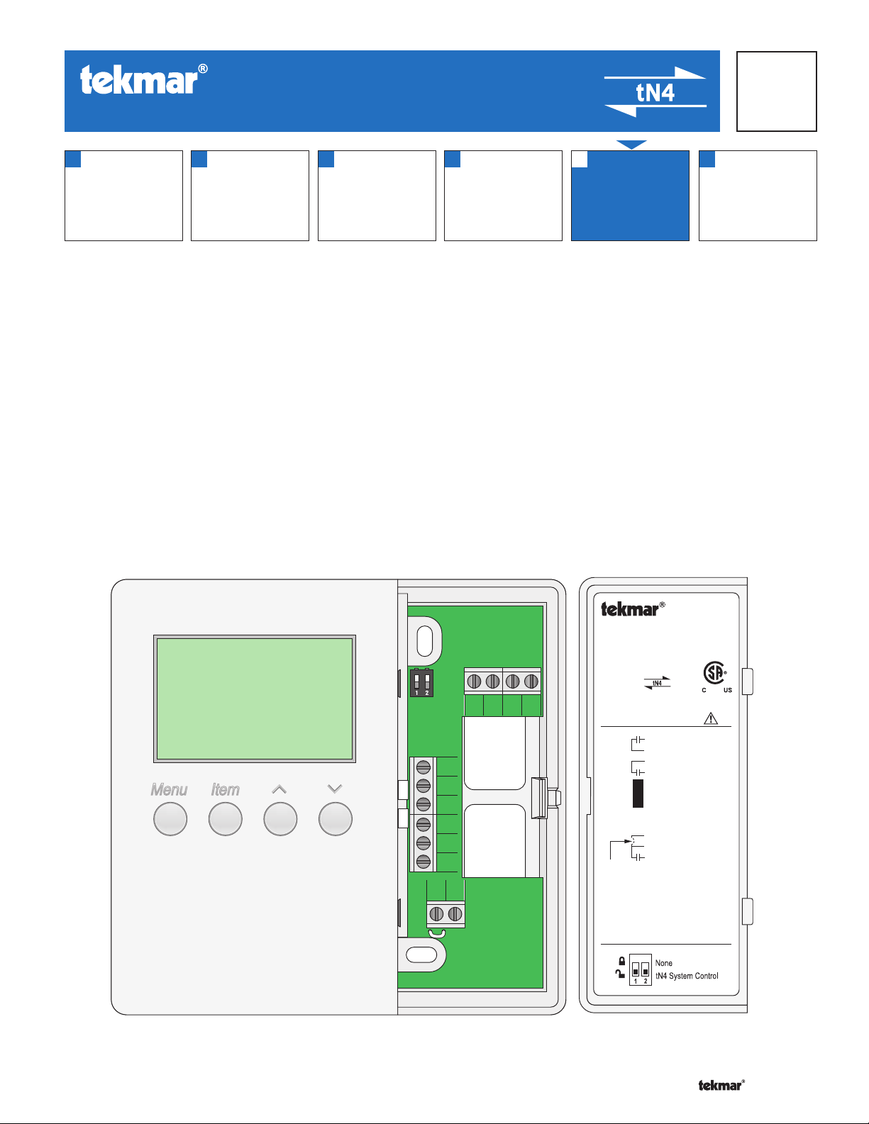
The tekmarNet®4 thermostat 544 operates one stage of heating equipment, one stage of cooling equipment, and one fan.
The fan operation includes logic to operate ventilation. The 544 can operate as a stand alone device, or communicate with
a group of tekmarNet®4 thermostats.
Features
• tN4 Compatible
• Automatic Heat / Cool Switchover
• 2 Auxiliary Temperature Sensor Inputs
• Pulse Width Modulation
• Programmable Setback and Setup Scheduling
• Scenes
Com
S2
S1
tN4
Rh1
Y1 Rc G1 G1
C
R
W1
tNt 544
One Stage Heat, One Stage Cool, One Fan
Power: 24 V (ac) ±10% 60 Hz 1.5 VA
Relays: 24 V (ac) 2 A
992-03
Meets Class B: Canadian ICES, FCC Part 15
Terminal Functions
G1
Fan 1 Relay
G1
Fan 1 Relay
Rc
Power Cooling
Y1
Cool 1 Relay
Com
Sensor Common
S2
Sensor 2
No Power
S1
Sensor 1
®
tekmarNet 4
Power Neutral
Power 24 V (ac)
Heat 1 Relay
Heat 1 Relay
To isolate
relay, cut
jumper
tN4
C
R
Rh1
W1
DIP Switch Functions
1 of 36 © 2008 D 544 - 07/08
Page 2
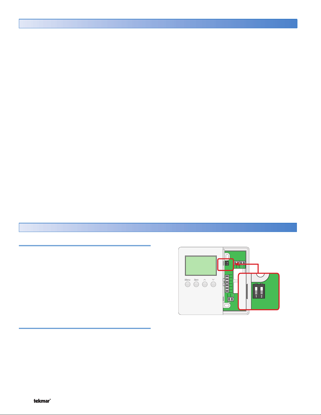
Table of Contents
Table of Contents ............................................................2
Display and DIP Switches ..............................................2
Dip Switches ...........................................................2
Access Levels .........................................................3
Display and Symbols Description............................3
User Interface .........................................................4
Setup ..............................................................................5
View Menu .............................................................5
Adjust Menu ............................................................6
Time Menu ............................................................10
Scene Menu .......................................................... 11
Schedule Menu ..................................................... 13
Monitor Menu ........................................................ 16
Test Menu .............................................................17
Miscellaneous Menu ............................................18
Thermostat Operation ..................................................20
Auxiliary Sensors .................................................20
Heat or Cool Mode of Operation ..........................20
Adjusting the Temperature ...................................21
Cycles Per Hour ...................................................22
Heating Terminal Units .........................................23
Heating Operation ................................................24
Cooling Operation ................................................25
Fan Operation ......................................................25
Time Clock ...........................................................26
Setting the Schedule .............................................26
Optimum Start / Stop ...........................................27
Scenes .................................................................28
Away Hold ............................................................29
Offset ...................................................................29
Warm Weather Shutdown ....................................29
Units of Temperature ............................................29
Backlight ..............................................................29
tN4 Address .........................................................30
Pump Exercising ...................................................30
Error Messages ............................................................31
Cleaning the Thermostat .............................................35
Warranty .......................................................................36
Display and DIP Switches
Dip Switches
tN4 System Control (DIP Switch #2)
A tN4 System Control is a control, not a thermostat, that
the 544 thermostat connects to through the tN4 bus. All
tN4 compatible Outdoor Reset Modules are tN4 System
Controls.
• If the thermostat is connected to a tN4 System Control,
set the tN4 System Control DIP switch to tN4 System
Control (down position).
• If the thermostat is not connected to a tN4 System
Control, set the tN4 System Control DIP switch to None
(up position).
Lock / Unlock (DIP Switch #1)
Use the Lock / Unlock DIP switch to lock or unlock the
Access Level of the 544.
• To unlock the Access Level, set the DIP switch to the
unlocked (down) position.
• To lock the Access Level, set the DIP switch to the locked
(up) position. Once locked, a padlock is displayed in the
lower right corner of the display and the Access Level
cannot be changed.
Y1 Rc G1 G1
Com
S2
S1
tN4
C
R
W1
Rh1
Note: The tN4 System Control’s Lock / Unlock DIP switch
overrides the Lock / Unlock DIP switch on the 544. Set
the tN4 System Control’s Lock / Unlock DIP switch to the
Unlock position before Access Levels can be changed on
the thermostat.
© 2008 D 544 - 07/08 2 of 36
Page 3
Access Levels
The Access Level restricts the number of Menus, Items
and Adjustments that can be accessed by the user. The
Access Level setting is found in the Miscellaneous (MISC)
menu. Select the appropriate access level for the people
who work with the thermostat on a regular basis.
The 544 has five Access Levels:
• Advanced (ADV): access to all settings
• Installer (INST): settings required for installation
• User (USER): for property owners
• Limited (LTD): limited temperature adjustment
• Secure (SEC): for commercial and public installations
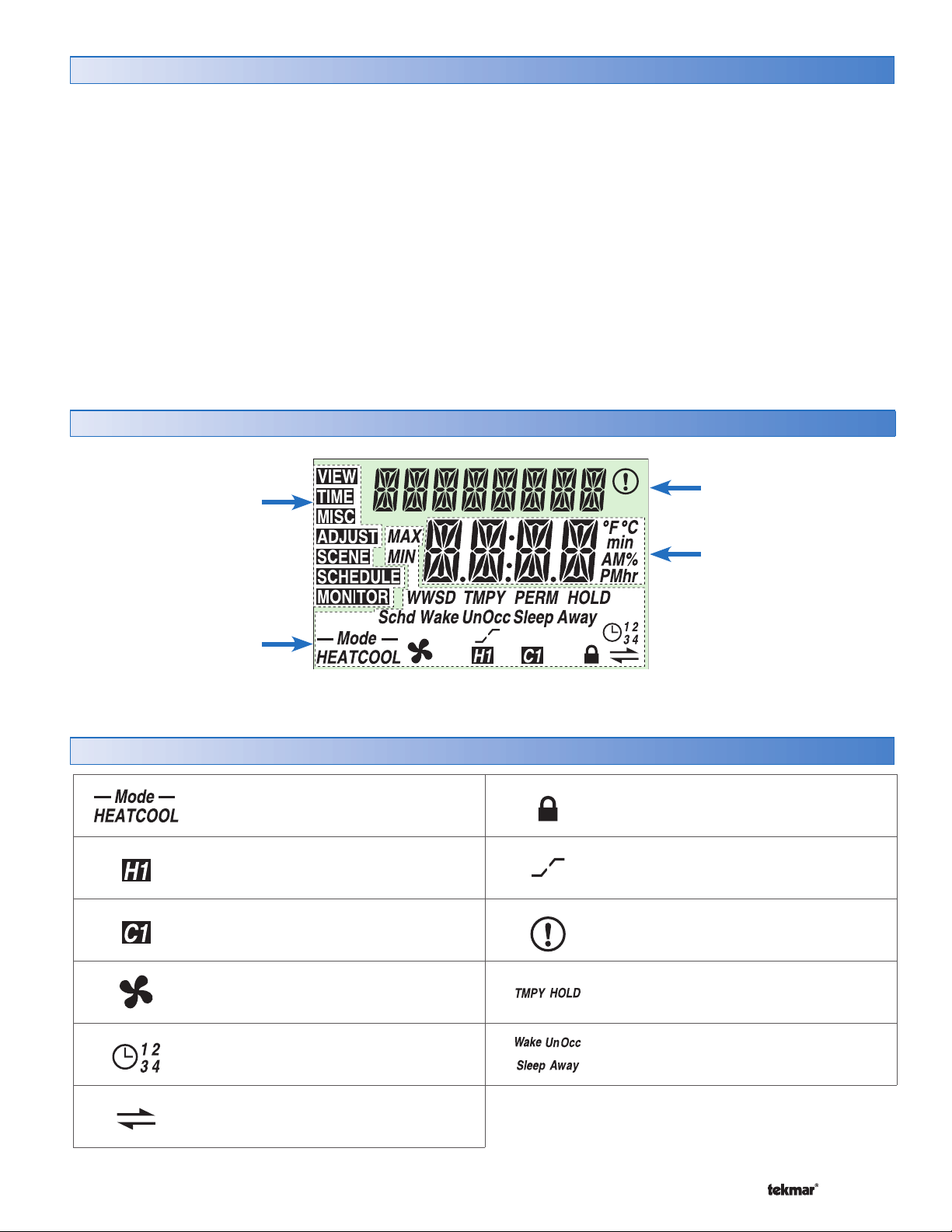
Display
Menu Field
Displays the
current menu
Status Field
Displays the current status
of the control’s inputs,
outputs and operation
For more information, see the Misc (Miscellaneous) Menu
section.
In the following menu tables, the access level the item is
visable in is shown in the access column.
To adjust the Access Level:
1. Set the Unlock / Lock DIP switch to the unlock position.
If a tN4 System Control is connected to the 544, the
Unlock / Lock DIP switch on the tN4 System Control
must be set to the unlock position.
2. Use the Menu button to select the Misc menu.
3. Use the Item button to select the Access menu item.
4. Use the Up and Down button to select the required
Access Level.
Item Field
Displays an abbreviated
name of the selected item
Number Field
Displays the current value
of the selected item
Symbols Description
MODE OF OPERATION
Displays whether the device is in heating
or cooling mode.
FIRST STAGE HEAT
First stage heating is operating.
FIRST STAGE COOL
First stage cooling is operating.
FAN
Fan is operating.
SCHEDULE MASTER
Indicates that this thermostat is a
schedule master.
tN4 COMMUNICATION
A tN4 network is detected.
3 of 36 © 2008 D 544 - 07/08
LOCK
The Access Levels are locked. A menu
option is visible but not adjustable.
OPTIMUM START / STOP
The Optimum Start or Optimum Stop
feature is active.
WARNING
An error is present.
TEMPORARY HOLD
The temperature has been temporarily
adjusted from the scheduled event.
SCHEDULED EVENT
Displays the current scheduled event.
Page 4
User Interface
Use the User Interface available on the Liquid Crystal Display
(LCD) to setup and monitor the operation of the thermostat.
Use the four push buttons below the LCD (Menu, Item, Up,
Down) to select settings. As you enter settings, record the
settings in the Job Record J 544.
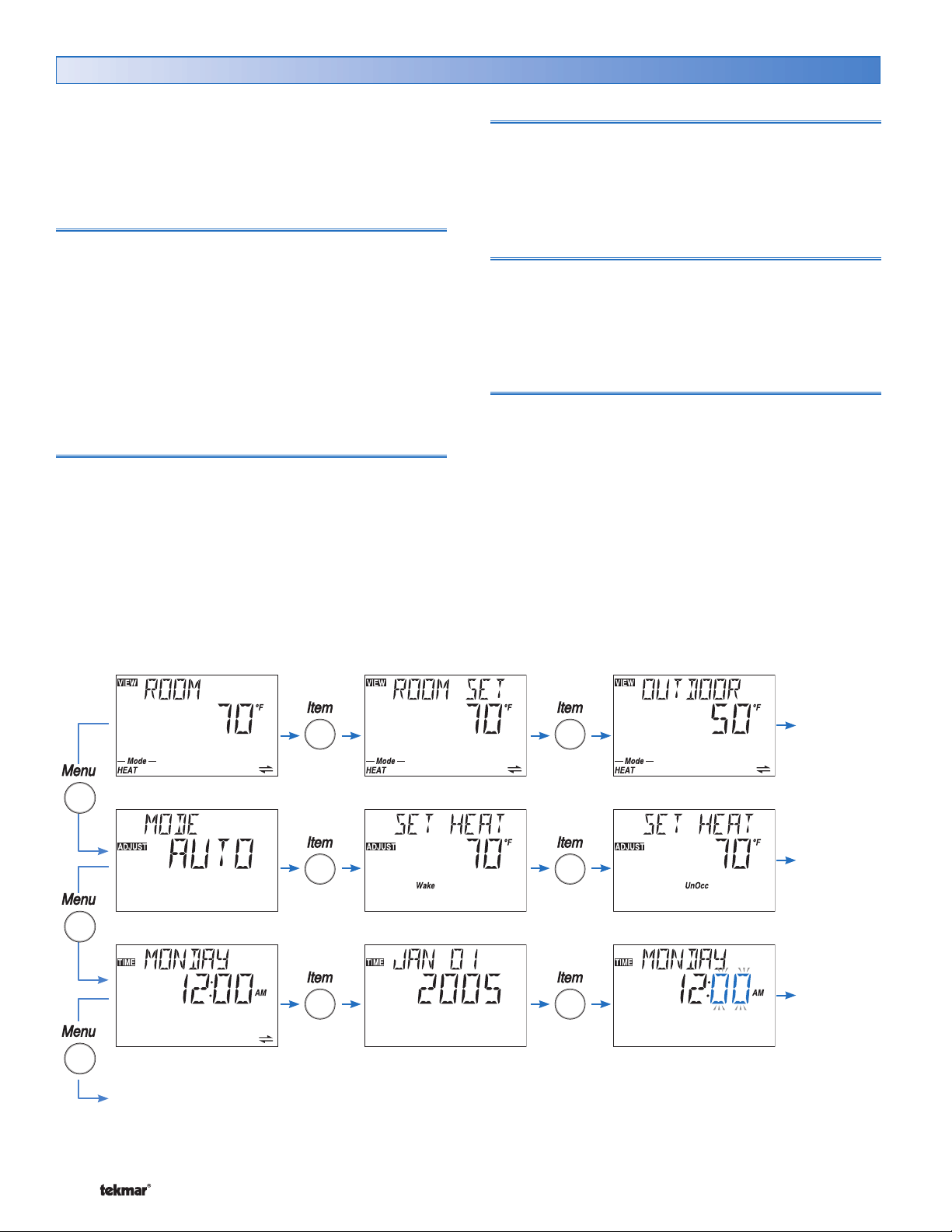
Menu
The menus display in the Menu Field at the left of the
LCD.
Seven menus are available:
• View
• Adjust
• Time
• Schedule
• Monitor
• Miscellaneous
• Scene
To select a menu, press and release the Menu button.
Item
In each menu, a group of items can be selected. The
abbreviated name of the selected item displays in the Item
field of the LCD display.
• To view the next available item, press and release the
Item button.
• To view the previous item, hold down the Item button
and press and release the Up button.
Adjusting a Setting
To adjust a setting:
1. Use the Menu button to select the appropriate menu.
2. Use the Item button to select a menu item.
3. Use the Up or Down button to adjust the setting.
Default Item
• To set the default item in the View Menu, display the
item for more than five seconds.
After navigating menus, the display reverts back to the
default item after 60 seconds of button inactivity.
Copy Settings
To save time in setting thermostats, you can copy the settings
from one tN4 thermostat to a second tN4 thermostat.
Refer to the COPY item in the Misc menu on page 18.
Continue to next Menu
Continue
to next Item
Continue
to next Item
Continue
to next Item
© 2008 D 544 - 07/08 4 of 36
Page 5
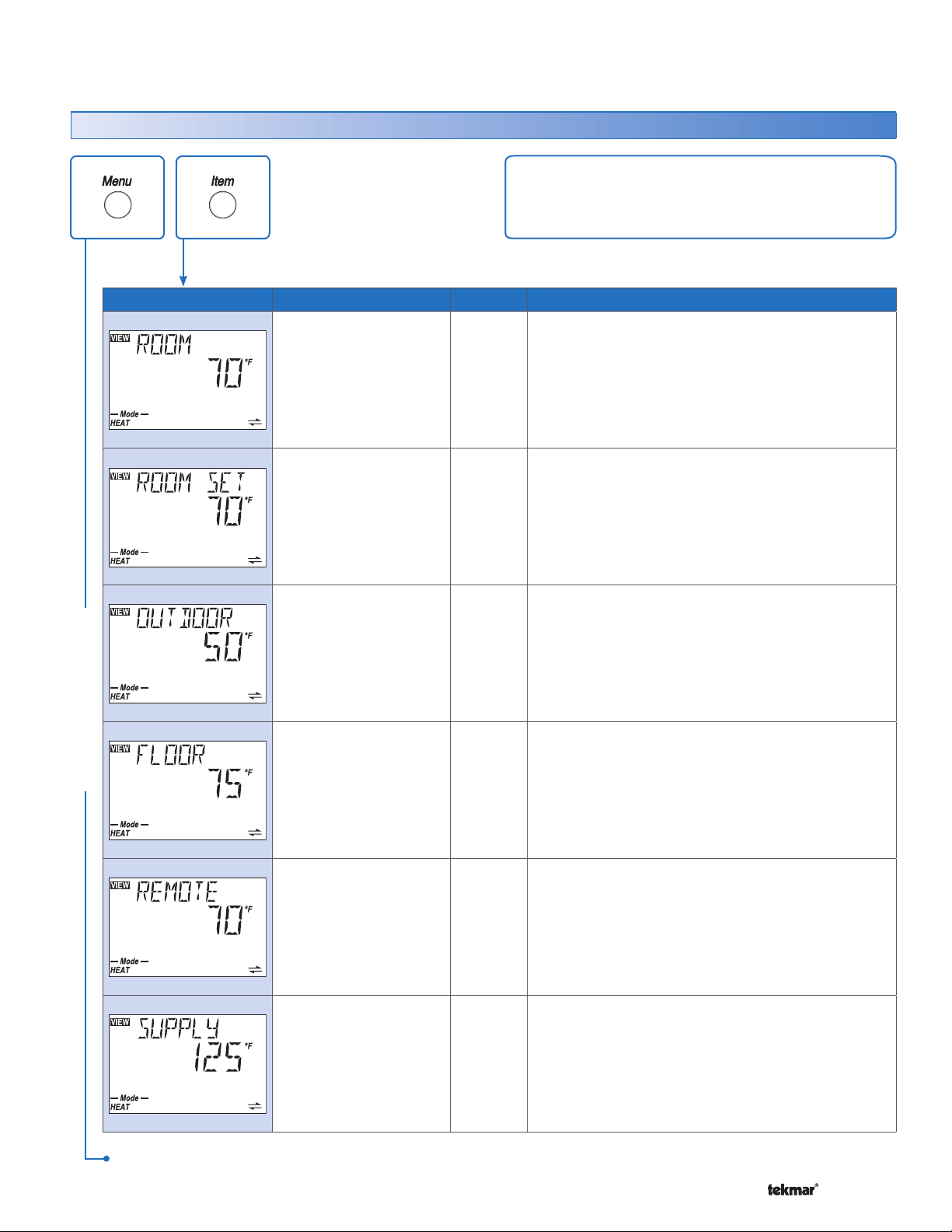
Display Menus
View Menu (1 of 1)
The View menu items display the current operating
temperatures and status information of the system.
Item Field Range
VIEW MENU
-58 to 212°F
(-50.0 to 100.0°C)
– – –, 40 to 95°F
(– – –, 4.5 to 35.0°C)
– – – (if no recent
message),
-58 to 212°F
(-50.0 to 100.0°C)
-58 to 212°F
(-50.0 to 100.0°C)
Access
SEC
LTD
USER
INST
ADV
USER
INST
ADV
SEC
LTD
USER
INST
ADV
SEC
LTD
USER
INST
ADV
Description
ROOM SECTION A
Current air temperature in the room.
Note: This item is only available when the Room Sensor
is set to On or Sensor 1 or 2 is set to Room.
ROOM SET SECTION A
Selected room temperature.
Note: This item is only available when the Room Sensor
is set to On or Sensor 1 or 2 is set to Room.
OUTDOOR SECTION A
Current temperature at the outdoor sensor.
Note: This item is only available when an outdoor
sensor is connected to the tN4 network.
FLOOR SECTION A
Current floor temperature.
Note: This item is only available when Sensor 1 or
2 is set to Floor.
-58 to 212°F
(-50.0 to 100.0°C)
-22 to 266°F
(-30.0 to 130.0°C)
After the last item, the control returns to the first item in the menu.
5 of 36 © 2008 D 544 - 07/08
USER
INST
ADV
INST
ADV
REMOTE SENSOR SECTION A
Current temperature at the remote sensor location.
Note: This item is only available when Sensor 1 is
set to Remote.
SUPPLY TEMPERATURE OF TN4 BUS
Actual water temperature of the tN4 bus for the first
stage of heat.
Note: This item is only available when the thermostat
is connected to an Outdoor Reset Module and the
DIP switch is set to tN4 System Control.
SECTION F
Page 6
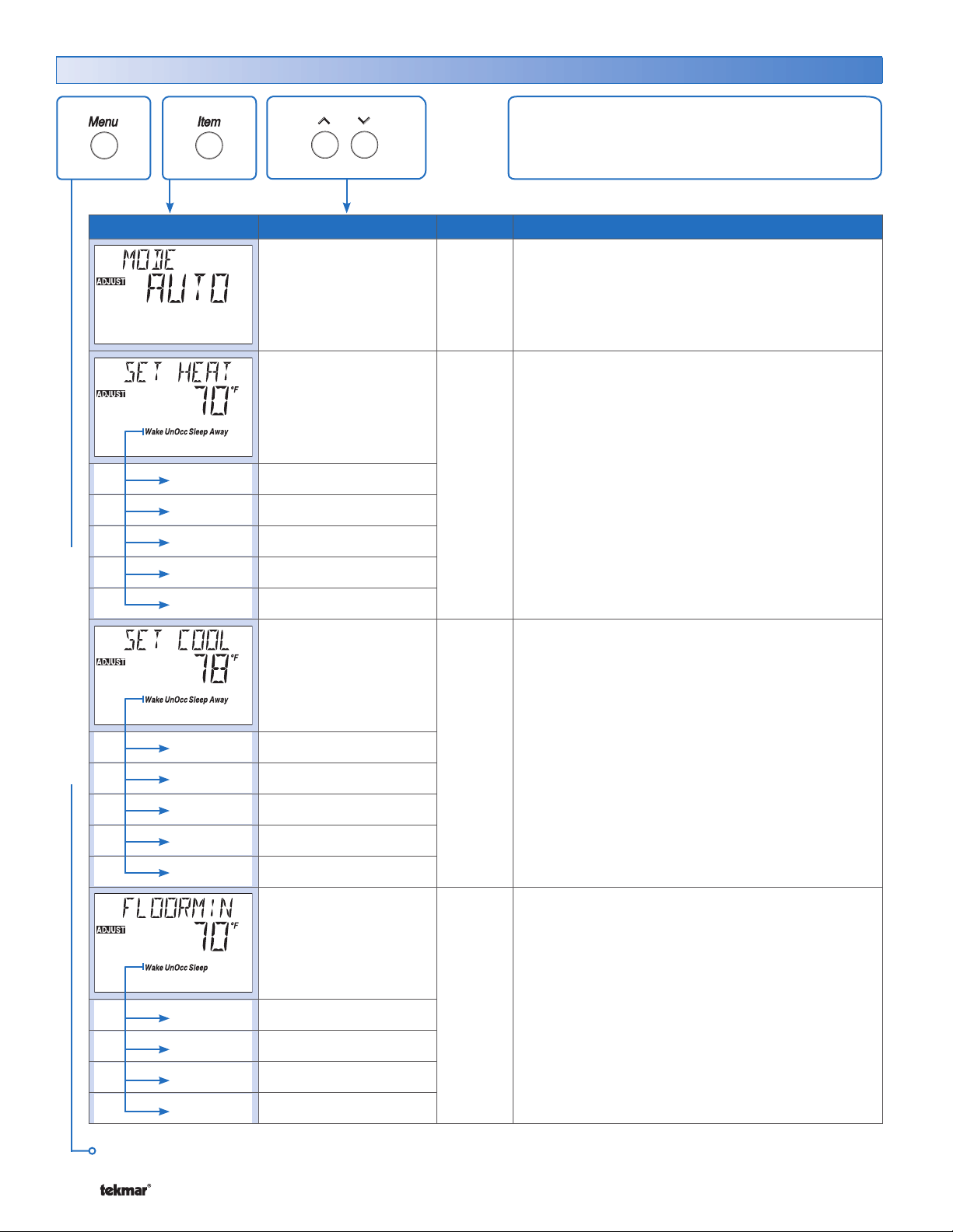
Adjust Menu (1 of 4)
Item Field Range Access Description
The Adjust Menu items are the programmable settings
used to operate the mechanical equipment.
Wake
UnOccupied
Occupied
Sleep
Away
Wake
ADJUST MENU
UnOccupied
Occupied
OFF, HEAT,
AUTO, COOL
Default = AUTO
40 to 95°F
(4.5 to 35.0°C)
Default = 70°F (21.0°C)
Default = 62°F (16.5°C)
Default = 70°F (21.0°C)
Default = 62°F (16.5°C)
Default = 62°F (16.5°C)
50 to 100°F
(10.0 to 38.0°C)
Default = 78°F (25.5°C)
Default = 85°F (29.5°C)
Default = 78°F (21.0°C)
USER
INST
ADV
LTD
USER
INST
ADV
LTD
USER
INST
ADV
MODE OF OPERATION SECTION B
Mode of operation of the thermostat or cool group.
SET HEAT SECTION C
Selected air heating temperature for each event.
Note: At the Limited Access Level, you can only
adjust the temperature +/-3°F (1.5°C) from the last
setting.
Away is only available when Scenes are turned on.
SET COOL SECTION C
Select the cooling room temperature for each event.
Note: At the Limited Access Level, you can only
adjust the temperature +/-3°F (1.5°C) from the last
setting.
Away is only available when Scenes are turned on.
Sleep
Away
Wake
UnOccupied
Occupied
Sleep
Continued on next page.
© 2008 D 544 - 07/08 6 of 36
Default = 85°F (29.5°C)
Default = 85°F (29.5°C)
OFF, 40 to 122°F
(OFF, 4.5 to 50.0°C)
Default = 70°F (21.0°C)
Default = OFF
Default = 70°F (21.0°C)
Default = OFF
LTD
USER
INST
ADV
FLOOR MINIMUM SECTION F
Select the minimum floor temperature for each
event.
Note: This item is only available when Sensor 1 or 2
is set to Floor. At the Limited Access Level, you can
only adjust the temperature +/-3°F (1.5°C) from the
last setting.
Page 7
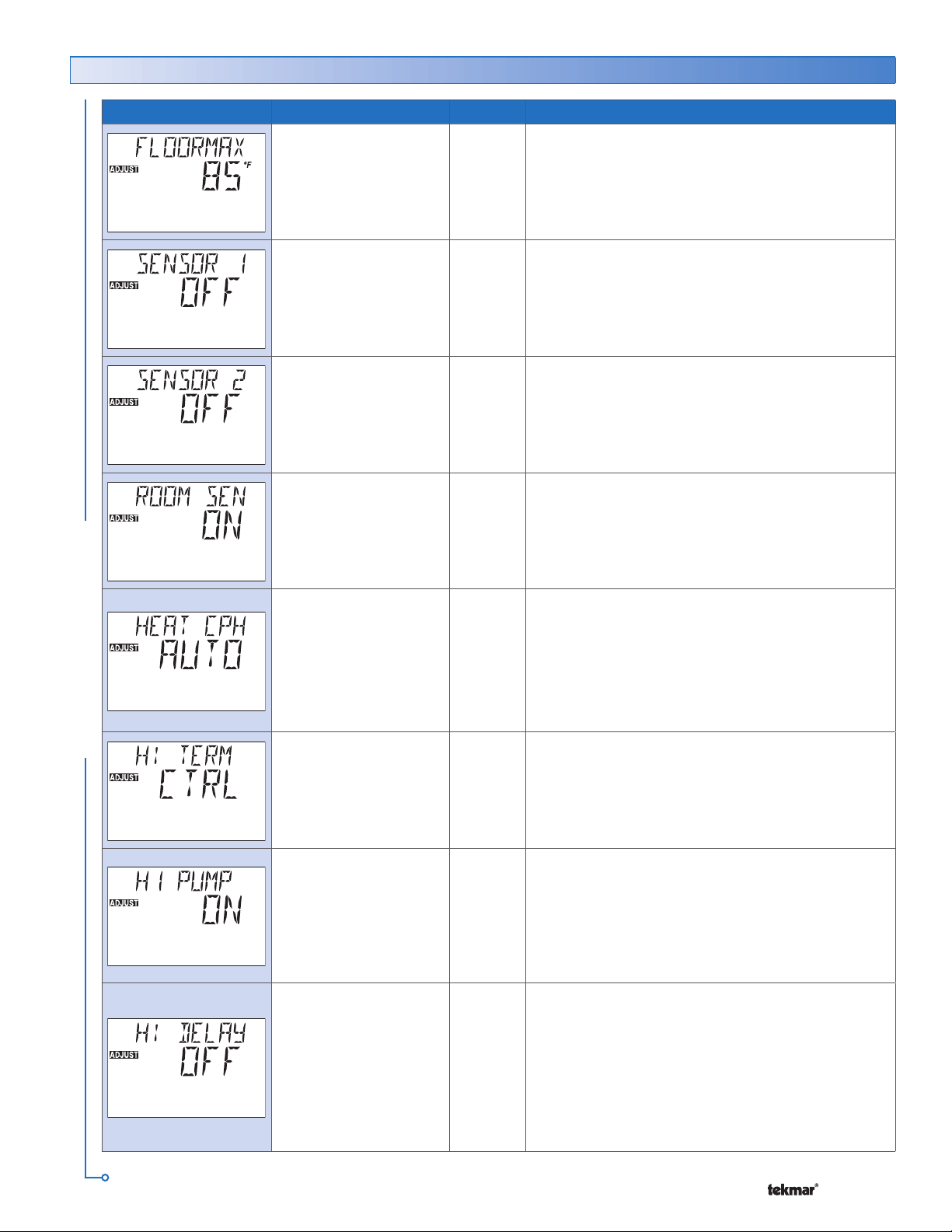
Adjust Menu (2 of 4)
Item Field Range Access Description
40 to 122°F
(4.5 to 50.0°C)
Default = 85°F
(29.5°C)
OFF, ROOM,
FLOR (Floor),
REM (Remote)
Default = OFF
OFF, ROOM,
FLOR (Floor),
OUT (Outdoor)
Default = OFF
OFF, ON
Default = ON
ADV
INST
ADV
INST
ADV
INST
ADV
FLOOR MAXIMUM
Maximum floor temperature.
Note: This item is only available when Sensor 1 or
2 is set to Floor.
SENSOR 1 SECTION A
Select the type of sensor connected to auxiliary
sensor input 1.
SENSOR 2 SECTION A
Select the type of sensor connected to auxiliary
sensor input 2.
ROOM SENSOR SECTION A
Selects whether the built-in room sensor is functional.
SECTION F
ADJUST MENU
SYNC, AUTO
2 to 12
Default = AUTO
CTRL, HRF1, HRF2,
COIL, CONV, RAD,
BASE, OTHR ,FURN
Default =CTRL
OFF, ON
Default = ON
OFF, ON
Default = OFF
ADV
INST
ADV
INST
ADV
INST
ADV
HEAT CYCLES PER HOUR SECTION D
Select the number of heating cycles per hour. SYNC
results in 5 CPH. All tN4 thermostats that are connected
and have the SYNC setting selected synchronize their
cycle to the same starting time.
Note: This item is only available when the tN4 System
Control DIP switch is set to Off.
HEAT 1 TERMINAL SECTION E
Select the type of heating terminal for first stage
heat.
Note: If CTRL is selected, the terminal unit selected
on the tN4 System Control is used.
HEAT 1 PUMP SECTION F
Select whether the system, primary, or mixing pump
on a tN4 System Control must operate while the first
stage heat is operating.
Note: This item is only available when the H1 Terminal
item is set to CTRL, HRF1, HRF2, Fan Coil, Convector,
Radiator, or Baseboard.
HEAT 1 DELAY SECTION F
Select whether the system, primary, or mixing pump
on a tN4 System Control is delayed to allow a first
stage heat thermal motor zone valve to open. Select
On for thermal motor, select Off for zone pump or
motorized zone valve.
Note: This item is only available when the H1 Terminal
item is set to CTRL, HRF1, HRF2, Fan Coil, Convector,
Radiator, or Baseboard.
Continued on next page.
7 of 36 © 2008 D 544 - 07/08
Page 8
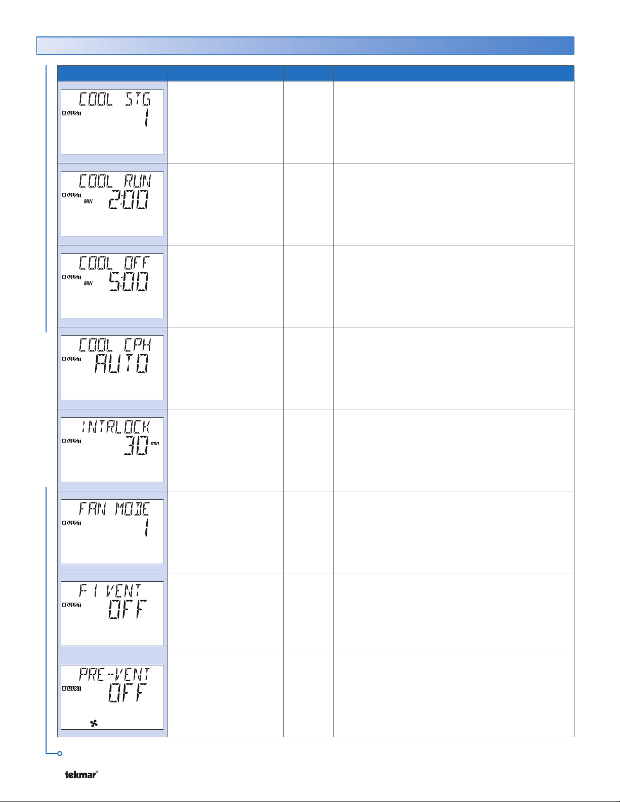
Adjust Menu (3 of 4)
Item Field Range Access Description
NONE, 1
Default = 1
0:30 to 6:00 min
Default = 2:00
0:30 to 10:00 min
Default = 5:00
AUTO, 2 to 12
Default = AUTO
INST
ADV
ADV
ADV
ADV
COOL STAGES SECTION G
Select the number of cooling stages. Select None if
cooling is not used.
MINIMUM COOL RUN TIME SECTION G
Select the minimum running time for the cooling
equipment.
Note: This item is only available when the Cool Stage
is set to 1.
MINIMUM COOL OFF TIME SECTION G
Select the minimum off time for the cooling
equipment.
Note: This item is only available when the Cool Stage
is set to 1.
COOL CYCLES PER HOUR SECTION D
Select the number of cooling cycles per hour.
Note: This item is only available when the Cool Stage
is set to 1.
ADJUST MENU
10 to 180 min
Default = 30
NONE, 1, 2
Default = 1
OFF, ON
Default = OFF
OFF, 1 to 60 min
Default = OFF
ADV
INST
ADV
ADV
ADV
INTERLOCK SECTION G
Select how long heating must be off before cooling
starts.
Note: This item is only available when the Cool Stage
is set to 1.
FAN MODE SECTION H
Select the operation of the Fan 1 output.
FAN VENTILATION SECTION H
Select whether the Fan output is required for
ventilation.
Note: This item is only available when the Fan Mode
is set to None.
VENTILATION PRE-VENT SECTION H
Select how long the ventilation operates continuously
prior to the Wake or Occupied events.
Note: This item is only available when the Fan Mode
is set to None and F1 Vent is set to On.
Continued on next page.
© 2008 D 544 - 07/08 8 of 36
Page 9
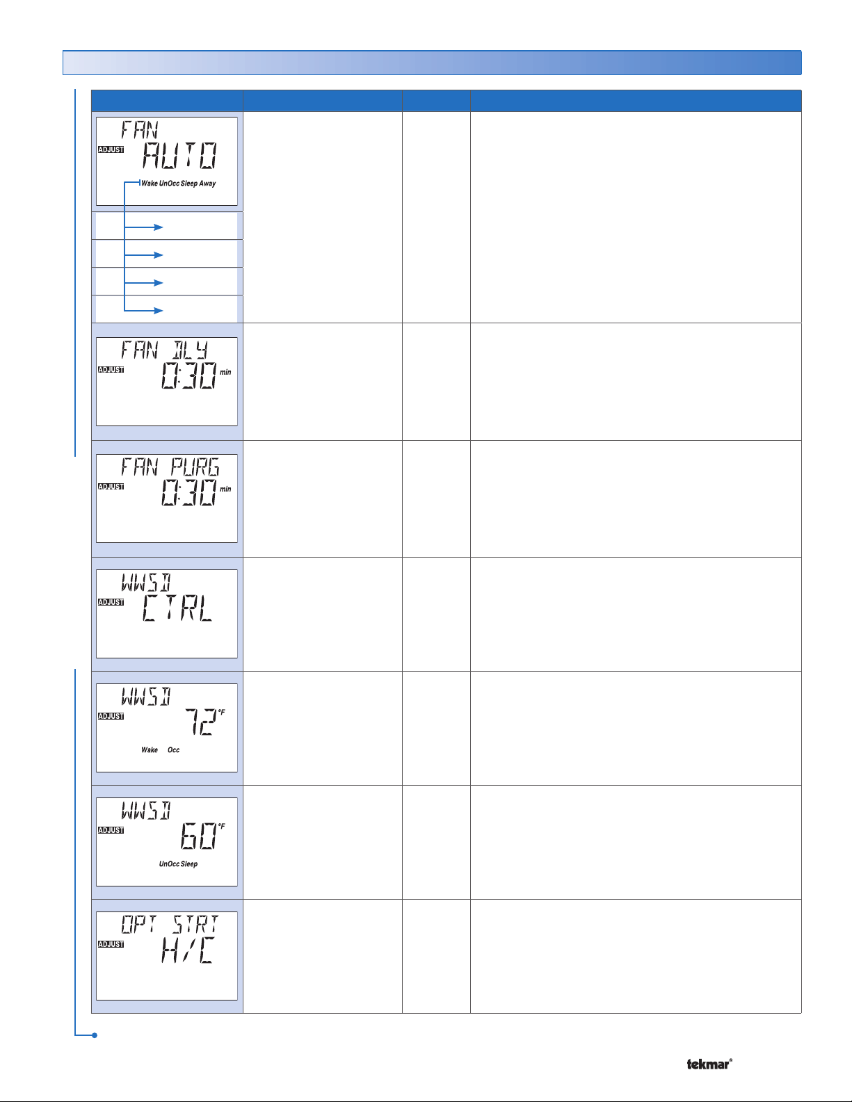
Adjust Menu (4 of 4)
Item Field Range Access Description
Wake
UnOccupied
Occupied
Sleep
AUTO, OFF,
10% to 90%, ON
Default = AUTO
0:00 to 2:00 min
(10 sec increments)
Default = 0:30
0:00 to 3:00 min
(10 sec increments)
Default = 0:30
LTD
USER
INST
ADV
ADV
ADV
FAN OPERATION
The minimum percentage of time the ventilation fan
operates during each event.
Auto operates with heat or cool.
On operates continuously.
% sets a minimum On time for each cycle.
FAN DELAY SECTION H
Set the fan’s delay time after a heating zone calls for
heat. This allows the fan coil to heat up and prevents
the fan from blowing cold air.
Note: This item is only available when H1 Terminal is
set to Coil or Furnace and Fan Mode is set to 1 or 2.
FAN PURGE SECTION H
Set how long the fan operates after a call for heating or
cooling ends. This purges any heat or cold remaining
in the fan coil.
Note: This item is only available when H1 Terminal is
set to Coil or Furnace and Fan Mode is set to 1 or 2.
SECTION H
ADJUST MENU
NONE, ZONE, CTRL
Default = CTRL
40 to 100°F, OFF
(4.5 to 38.0°C, OFF)
Default = 72°F
(22.0°C)
40 to 100°F, OFF
(4.5 to 38.0°C, OFF)
Default = 60°F
(15.5°C)
HEAT, COOL,
H/C, OFF
Default = H/C
ADV
INST
ADV
INST
ADV
INST
ADV
WARM WEATHER SHUT DOWN SECTION O
Set the outdoor temperature at which warm weather
shutdown occurs. Select whether the thermostat
follows the tN4 System Control’s or the zone’s WWSD
for scheduled events.
WWSD OCCUPIED AND WAKE SECTION O
Set the Warm Weather Shut Down (WWSD) temperature
during Occupied and Wake events.
Note: This item is only available when WWSD is set
to Zone.
WWSD UNOCCUPIED AND SLEEP SECTION O
Set the Warm Weather Shut Down temperature during
Unoccupied and Sleep events.
Note: This item is only available when WWSD is set
to Zone.
OPTIMUM START / STOP SECTION K
Select whether to use Optimum Start / Stop for heating,
cooling, or both.
Note: This item is only available when a HeatCool
schedule is selected.
After the last item, the control returns to the first item in the menu.
9 of 36 © 2008 D 544 - 07/08
Page 10
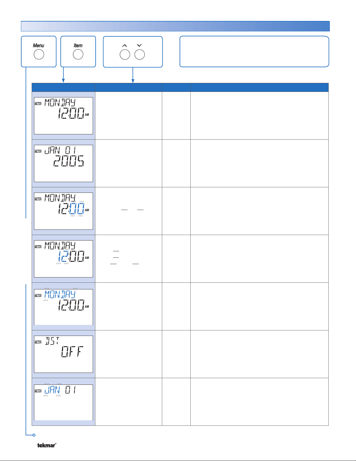
Time Menu (1 of 2)
The Time menu items set the time clock, day and date.
Item Field Range
TIME MENU
SUNDAY, MONDAY,
TUESDAY,
WEDNESDAY,
THURSDAY, FRIDAY,
SATURDAY
Default = MONDAY
Default = JAN 01 2007
12:00 to :59
Default = :12:00 AM
12:00 AM to
11:59 PM or
00:00 to 23:59
Default = 12:00 AM
Access
SEC
LTD
USER
INST
ADV
USER
INST
ADV
USER
INST
ADV
USER
INST
ADV
Description
CURRENT TIME AND DAY SECTION I
Displays the current time and day of the week. The
time and date flash if the time is not set.
CURRENT DATE SECTION I
Display the current month, day, and year. Use this date
to determine daylight savings time.
Note: This item is only available when Daylight Savings
Time (DST) is set to On.
CLOCK MINUTES SECTION I
Set the minutes.
CLOCK HOURS SECTION I
Set the hours.
SUNDAY ...
WEDNESDAY ...
SATURDAY
Default = SUNDAY
OFF, 1, 2
Default = OFF
JAN, FEB,
MAR ... DEC
Default = JAN
Continued on next page.
© 2008 D 544 - 07/08 10 of 36
USER
INST
ADV
INST
ADV
USER
INST
ADV
DAY OF THE WEEK SECTION I
Set the day of the week.
DAYLIGHT SAVINGS TIME SECTION I
Selects whether to use Daylight Savings Time. The
time is automatically adjusted if set to Mode 1 or 2.
Note: See page 26 for a description of DST Modes.
MONTH SECTION I
Set the current month of the year.
Note: This item is only available when Daylight Savings
Time is set to Mode 1 or 2.
Page 11
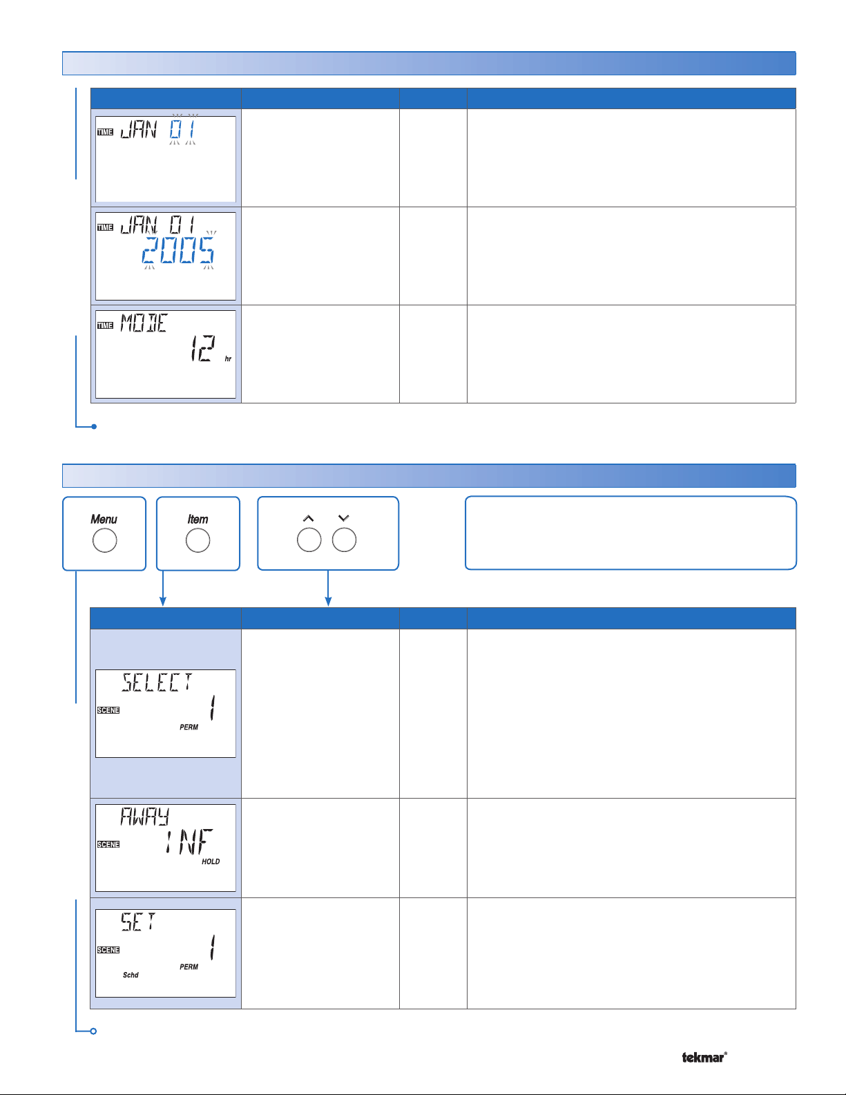
Time Menu (2 of 2)
Item Field Range
01 ... 31
(number of days is
dependent on month)
Default = 01
2000 ... 2255
Default = 2005
Access
USER
INST
ADV
USER
INST
ADV
TIME MENU
12 hr to 24 hr
Default = 12
After the last item, the control returns to the first item in the menu.
Scene Menu (1 of 2)
ADV
Description
DAY OF THE MONTH
Set the day of the month.
Note: This item is only available when Daylight Savings
Time is set to Mode 1 or 2.
YEAR SECTION K
Set the current year.
Note: This item is only available when Daylight Savings
Time is set to Mode 1 or 2.
MODE SECTION J
Select whether time should be displayed using a 12
or a 24 hour clock.
SECTION K
Item Field Range
SCENE MENU
Occ
Away
PERM1
PERM Away 2
PERM UnOcc 3,
PERM 4
PERM 5
TMPY Occ 6
TMPY 7
TMPY 8
Default = Occ PERM 1
INF, 1 to 180 days
Default = INF
Schd
Wake
Occ
UnOcc
Sleep
Away
Default = SCHD
Access
USER
INST
ADV
USER
INST
ADV
INST
ADV
The Scene Menu items set the current scene as
well as the scene settings.
Description
SELECT SECTION L
Select the scene for the building.
Note: Only Occ and AWAY are available when no
schedule is selected.
AWAY HOLD SECTION L
Set the number of days for the Permanent Away 2
scene. When the scene is selected, the thermostat
remains in that scene for the set number of days then
reverts to the last permanent scene.
SET PERMANENT 1 SECTION L
Select an action for the Permanent 1 scene.
Note: This item is only available when SCENE menu
is set to ON and a schedule has been selected.
Continued on next page.
11 of 36 © 2008 D 544 - 07/08
Page 12
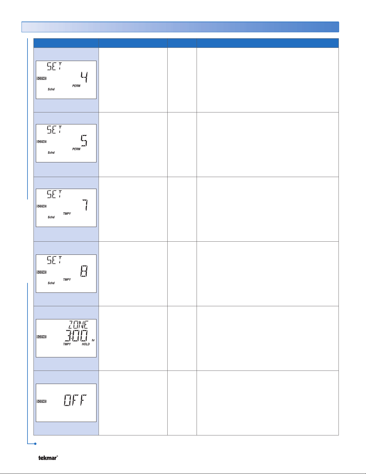
Scene Menu (2 of 2)
Item Field Range
Schd
Wake
Occ
UnOcc
Sleep
Away
Default = SCHD
Schd
Wake
Occ
UnOcc
Sleep
Away
Default = SCHD
Schd
Wake
Occ
UnOcc
Sleep
Away
Default = SCHD
Access
INST
ADV
INST
ADV
INST
ADV
Description
SET PERMANENT 4 SECTION L
Select an action for the Permanent 4 scene.
Note: This item is only available when SCENE menu
is set to ON and a schedule has been selected.
SET PERMANENT 5 SECTION L
Select an action for the Permanent 5 scene.
Note: This item is only available when SCENE menu
is set to ON and a schedule has been selected.
SET TEMPORARY 7 SECTION L
Select an action for the Temporary 7 scene. The
scene lasts for 4 hours before reverting to the previous
permanent scene.
Note: This item is only available when SCENE menu
is set to ON and a schedule has been selected.
SCENE MENU
Schd
Wake
Occ
UnOcc
Sleep
Away
Default = SCHD
1:00 to 10:00 hr
(½ hr intervals)
Default = 3:00
OFF. ON
Default = OFF
INST
ADV
USER
INST
ADV
INST
ADV
SET TEMPORARY 8 SECTION L
Select an action for the Temporary 8 scene. The
scene lasts for 8 hours before reverting to the previous
permanent scene.
Note: This item is only available when SCENE menu
is set to ON and a schedule has been selected.
TEMPORARY ZONE HOLD SECTION C
Select the number of hours the temporary hold affects
this zone.
SCENE MENU
Select the Scene feature of the thermostat.
SECTION L
After the last item, the control returns to the first item in the menu.
© 2008 D 544 - 07/08 12 of 36
Page 13
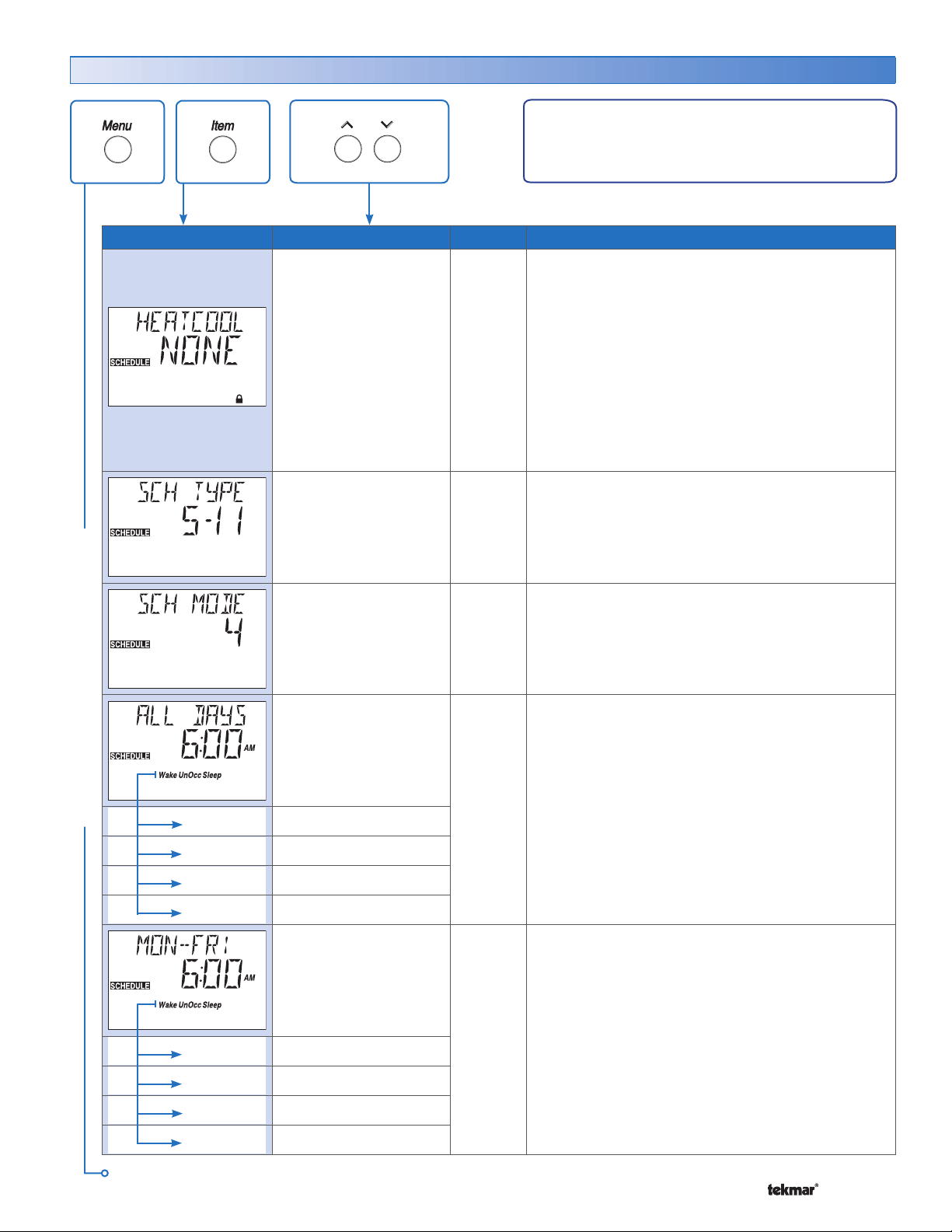
Schedule Menu (1 of 3)
The Schedule menu items set the schedule type, the
number of events per day, and the event times.
Item Field Range
NONE, ZONE,
MST1, MST2,
MST3, MST4,
MBR1, MBR2,
MBR3, MBR4
Default = NONE
24 hr, 5-2,
5-11, 7dAY
Default = 5-11
2 (Occ, UnOcc),
4 (Wake, UnOcc,
Occ, Sleep)
Default = 4
Access
USER
INST
ADV
USER
INST
ADV
USER
INST
ADV
Description
HEATCOOL SCHEDULE SECTION J
If a schedule is not required, select NONE.
If the schedule is only used by this thermostat, select
ZONE.
If the schedule is shared with other thermostats,
select MST1 to MST4.
If the schedule is set on another thermostat, select
MBR1 to MBR4.
Note: This item can be viewed in the USER and
INST access levels but can only be adjusted in the
ADV access level.
SCHEDULE TYPE SECTION J
Select the type of schedule.
Note: This item is only available when the HeatCool
Schedule is set to ZONE or MST1 to MST4.
SCHEDULE MODE SECTION J
Select the number of events per day.
Note: This item is only available when the HeatCool
Schedule is set to ZONE or MST1 to MST4.
– –:– – to 11:50 PM
or
– –:– – to 23:50
SCHEDULE MENU
Wake
UnOccupied
Occupied
Sleep
Wake
UnOccupied
Occupied
Sleep
Continued on next page.
13 of 36 © 2008 D 544 - 07/08
Default = 6:00 AM
Default = 8:00 AM
Default = 6:00 PM
Default = 10:00 PM
– –:– – to 11:50 PM
or
– –:– – to 23:50
Default = 6:00 AM
Default = 8:00 AM
Default = 6:00 PM
Default = 10:00 PM
USER
INST
ADV
USER
INST
ADV
ALL DAYS OF THE WEEK SECTION J
Select the times for the scheduled events.
Note: This item is only available when the Schedule
Type is set to 24 hr.
MONDAY THROUGH FRIDAY SECTION J
Select the times for the scheduled events.
Note: This item is only available when the Schedule
Type is set to 5-2 or 5-11.
Page 14
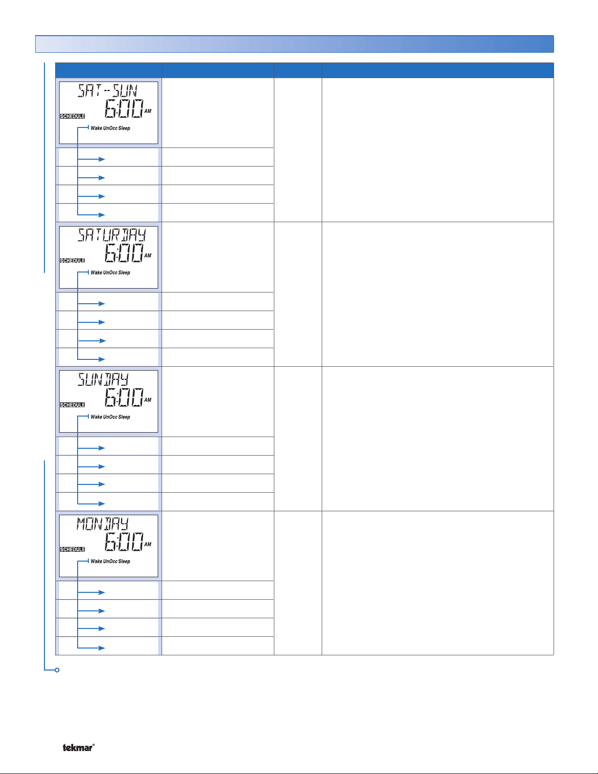
Schedule Menu (2 of 3)
Item Field Range
– –:– – to 11:50 PM
or
– –:– – to 23:50
Wake
UnOccupied
Occupied
Sleep
Wake
UnOccupied
Occupied
Default = 6:00 AM
Default = 8:00 AM
Default = 6:00 PM
Default = 10:00 PM
– –:– – to 11:50 PM
or
– –:– – to 23:50
Default = 6:00 AM
Default = 8:00 AM
Default = 6:00 PM
Access
USER
INST
ADV
USER
INST
ADV
Description
SATURDAY AND SUNDAY SECTION J
Select the times for the scheduled events.
Note: This item is only available when the Schedule
Type is set to 5-2.
SATURDAY SECTION J
Select the times for the scheduled events.
Note: This item is only available when the Schedule
Type is set to 5-11 or 7dAY.
Sleep
SCHEDULE MENU
Wake
UnOccupied
Occupied
Sleep
Wake
UnOccupied
Occupied
Default = 10:00 PM
– –:– – to 11:50 PM
or
– –:– – to 23:50
Default = 6:00 AM
Default = 8:00 AM
Default = 6:00 PM
Default = 10:00 PM
– –:– – to 11:50 PM
or
– –:– – to 23:50
Default = 6:00 AM
Default = 8:00 AM
Default = 6:00 PM
USER
INST
ADV
USER
INST
ADV
SUNDAY SECTION J
Select the times for the scheduled events.
Note: This item is only available when the Schedule
Type is set to 5-11 or 7dAY.
MONDAY SECTION J
Select the times for the scheduled events.
Note: This item is only available when the Schedule
Type is set to 7dAY.
Sleep
Continued on next page.
© 2008 D 544 - 07/08 14 of 36
Default = 10:00 PM
Page 15
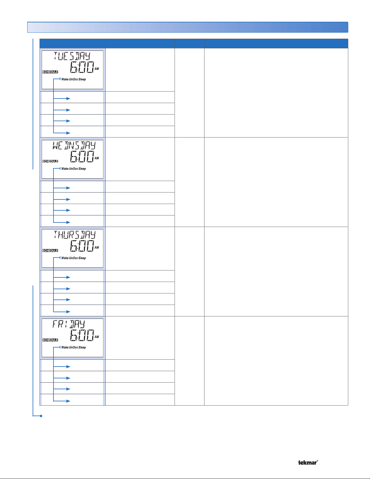
Schedule Menu (3 of 3)
Item Field Range
– –:– – to 11:50 PM
or
– –:– – to 23:50
Wake
UnOccupied
Occupied
Sleep
Wake
UnOccupied
Occupied
Default = 6:00 AM
Default = 8:00 AM
Default = 6:00 PM
Default = 10:00 PM
– –:– – to 11:50 PM
or
– –:– – to 23:50
Default = 6:00 AM
Default = 8:00 AM
Default = 6:00 PM
Access
USER
INST
ADV
USER
INST
ADV
Description
TUESDAY SECTION J
Select the times for the scheduled events.
Note: This item is only available when the Schedule
Type is set to 7dAY.
WEDNESDAY SECTION J
Select the times for the scheduled events.
Note: This item is only available when the Schedule
Type is set to 7dAY.
Sleep
SCHEDULE MENU
Wake
UnOccupied
Occupied
Sleep
Wake
UnOccupied
Occupied
Default = 10:00 PM
– –:– – to 11:50 PM
or
– –:– – to 23:50
Default = 6:00 AM
Default = 8:00 AM
Default = 6:00 PM
Default = 10:00 PM
– –:– – to 11:50 PM
or
– –:– – to 23:50
Default = 6:00 AM
Default = 8:00 AM
Default = 6:00 PM
USER
INST
ADV
USER
INST
ADV
THURSDAY SECTION J
Select the times for the scheduled events.
Note: This item is only available when the Schedule
Type is set to 7dAY.
FRIDAY SECTION J
Select the times for the scheduled events.
Note: This item is only available when the Schedule
Type is set to 7dAY.
Sleep
After the last item, the control returns to the first item in the menu.
15 of 36 © 2008 D 544 - 07/08
Default = 10:00 PM
Page 16
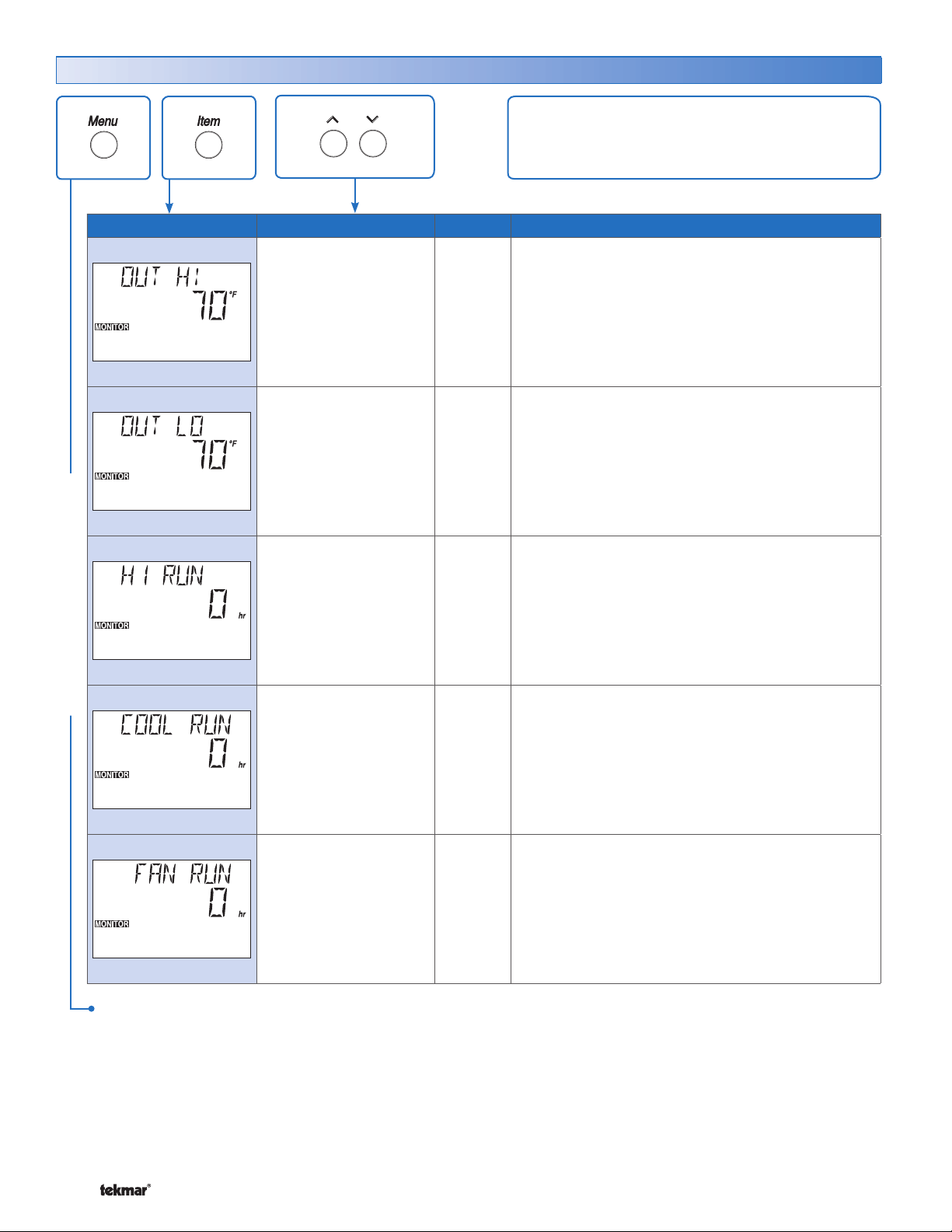
Monitor Menu (1 of 1)
The Monitor menu items record the high and low
temperatures and the number of running hours of
mechanical equipment.
Item Field Range
-76 to 149°F
(-60.0 to 65.0°C)
-76 to 149°F
(-60.0 to 65.0°C)
0 to 9999 hr
Access
LTD
USER
INST
ADV
LTD
USER
INST
ADV
INST
ADV
Description
OUTDOOR HIGH SECTION A
Records the highest outdoor temperature. Press Up
and Down buttons to clear.
Note: This item is only available when an outdoor
sensor is connected to the tN4 network.
OUTDOOR LOW SECTION A
Records the lowest outdoor temperature. Press Up
and Down buttons to clear.
Note: This item is only available when an outdoor
sensor is connected to the tN4 network.
HEAT 1 RUN TIME SECTION F
Records the number of hours that first stage heat
runs. Press Up and Down buttons to clear.
MONITOR MENU
0 to 9999 hr
0 to 9999 hr
After the last item, the control returns to the first item in the menu.
INST
ADV
INST
ADV
COOL RUN TIME SECTION G
Records the number of hours that first stage cool
runs. Press Up and Down buttons to clear.
Note: This item is only available when the thermostat
is used for cooling.
FAN RUN TIME SECTION H
Records the number of hours the Fan runs. Press
Up and Down buttons to clear.
Note: This item is only available when Fan Mode is
set to 1 or 2.
© 2008 D 544 - 07/08 16 of 36
Page 17
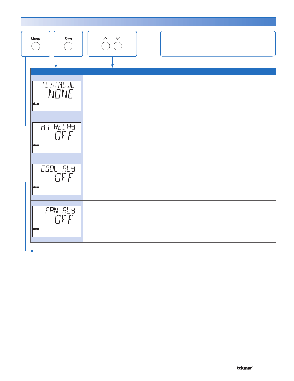
Test Menu (1 of 1)
The Test Menu Items allow for testing of each relay
on the thermostat.
Item Field Range
TEST MENU
NONE, AUTO, MAN
Default = NONE
OFF, ON
Default = OFF
OFF, ON
Default = OFF
OFF, ON
Default = OFF
Access
ADV
ADV
ADV
ADV
Description
TEST MODE
Select either manual or automatic test sequence of
the thermostat.
HEAT 1 RELAY
Manually turn on Heat 1 Relay for up to 5 minutes.
Note: This item is only available when Test Mode
is manual.
COOL RELAY
Manually turn on Cool Relay for up to 5 minutes.
Note: This item is only available when Cool Stage is
set to 1 and Test Mode is manual.
FAN RELAY
Manually turn on Fan Relay for up to 5 minutes.
Note: This item is only available when Fan Mode is
set to 1 or 2 or F1 Vent is set to On and Test Mode
is manual.
After the last item, the control returns to the first item in the menu.
17 of 36 © 2008 D 544 - 07/08
Page 18
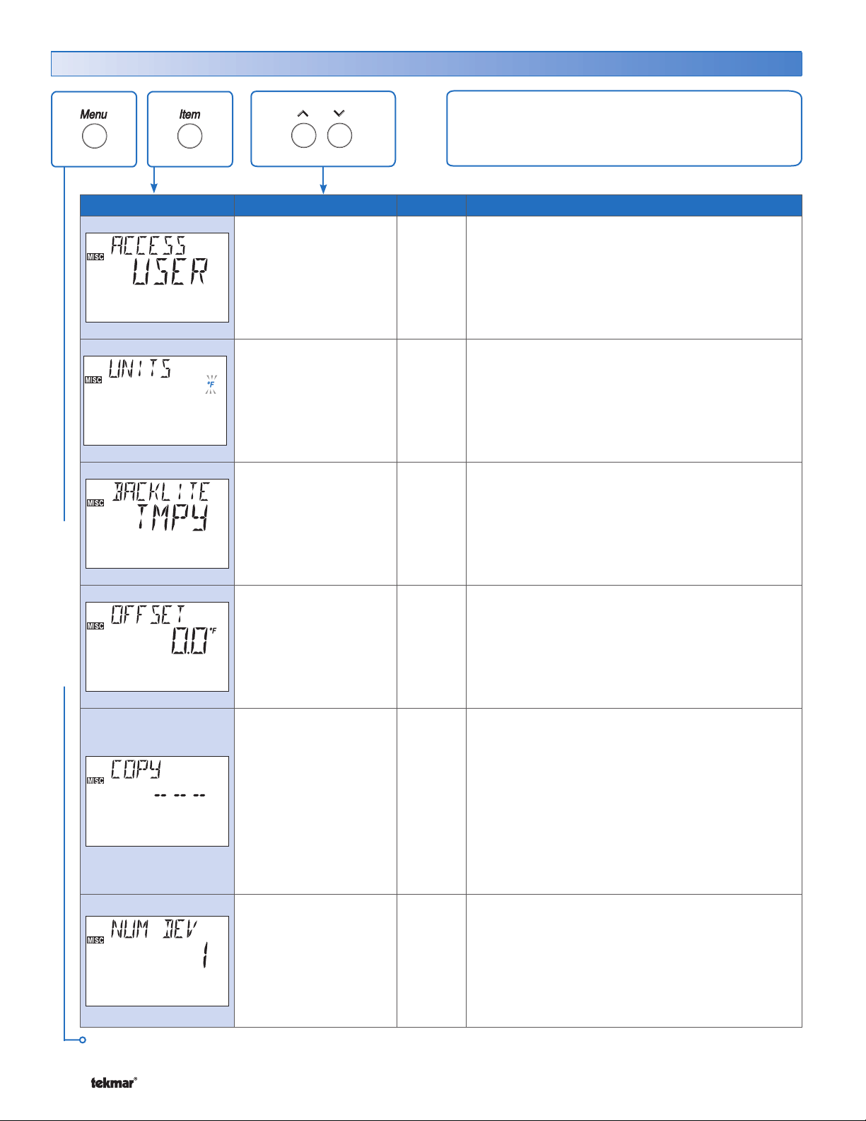
Misc (Miscellaneous) Menu (1 of 2)
The Miscellaneous menu items set display and control
options such as access level and temperature units.
Item Field Range
MISC MENU
LTD, USER,
INST, ADV
Default = USER
°F, °C
Default = °F
ON, TMPY, OFF
Default = TMPY
-5.0 to +5.0°F in
0.1°F increments
(-3.0° to +3.0°C in
0.1°C increments)
Default = 0.0°F
Access
SEC
LTD
USER
INST
ADV
USER
INST
ADV
USER
INST
ADV
ADV
Description
ACCESS LEVEL
The access level of the thermostat. The access column
shows which items are visible in each access level.
Note: This item is only available when the Lock /
Unlock DIP switch on the thermostat and the tN4
system control are set to Unlock.
UNITS SECTION P
Select Fahrenheit or Celsius as the temperature
units.
BACKLIGHT SECTION Q
Select whether the backlight displays permanently,
temporarily, or is off. The temporary backlight lasts
for 30 seconds.
OFFSET SECTION N
Fine tune the current room temperature. Adjustments
are in tenths of a degree.
– – –, -bus#:01,
... bus#:24, DEF
Default = – – –
1 to 24 ADV
Continued on next page.
© 2008 D 544 - 07/08 18 of 36
INST
ADV
COPY SETTINGS
Copy settings from another thermostat to this
thermostat.
1. Select the address of the thermostat to copy from.
Select DEF to load the factory default settings.
2. Wait for 3 seconds and then press the Up and Down
buttons for 1 second.
3.
The thermostat will show the percentage of progress.
4. Displays DONE if successful or WARN if only part
of the settings were copied.
NUMBER OF DEVICES SECTION R
Number of tN4 devices connected to this tN4 bus.
Note: This item is only available when the thermostat
is connected to a tN4 bus.
Page 19
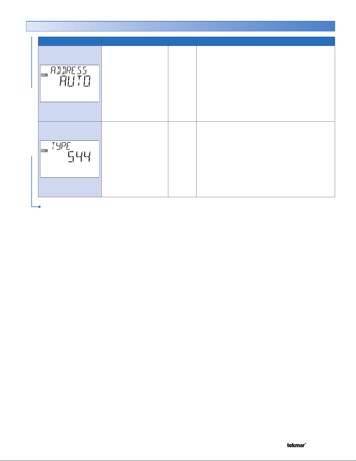
Misc (Miscellaneous) Menu (2 of 2)
Item Field Range
AUTO, -bus#:01,
... bus#:24
Default = AUTO
MISC MENU
544, Software Version
After the last item, the control returns to the first item in the menu.
Access
SEC
LTD
USER
INST
ADV
SEC
LTD
USER
INST
ADV
Description
ADDRESS SECTION R
The tN4 bus address of this thermostat.
Auto allows the tN4 system to automatically assign
an address to the thermostat.
To manually set the address, use the Up or Down
buttons while in the ADV or INST access level.
Note: This item is only available when the thermostat
is connected to a tN4 bus.
TYPE
Product number of this thermostat. Hold the Up button
to view the software version.
19 of 36 © 2008 D 544 - 07/08
Page 20
Thermostat Operation
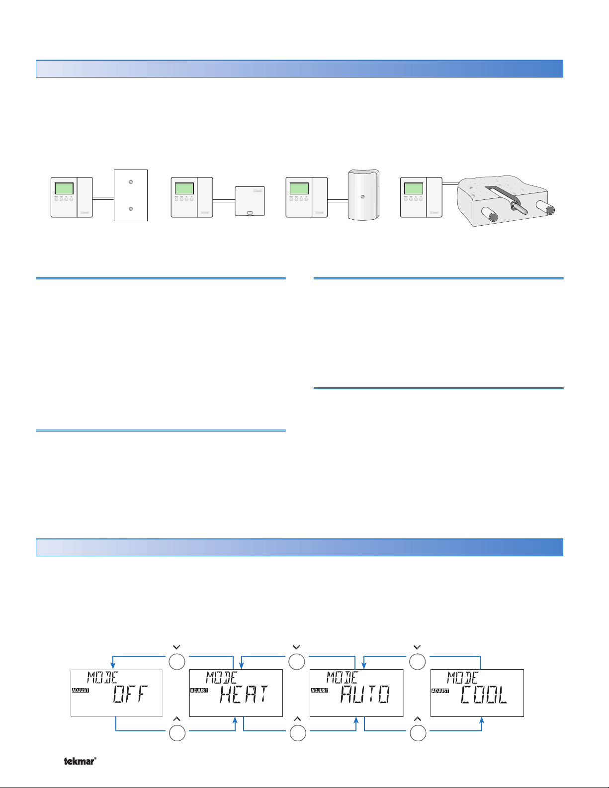
Auxiliary Sensors Section A
The thermostat has a built-in sensor to measure air
temperature at the thermostat. In addition to the built-in
sensor, the thermostat has terminals to connect up to
two separate auxiliary sensors. These sensors can either
be room sensors, floor sensors, a remote sensor or an
outdoor sensor.
Indoor Sensor 076 Outdoor Sensor 070Indoor Sensor 077 Slab Sensor 079
Room Sensor
A room sensor measures the air temperature in the zone
that the thermostat controls. This measurement is used
to calculate on times for heating and cooling operations.
Up to two auxiliary sensor inputs can be configured for a
room sensor. If additional room sensors are installed, the
thermostat averages the room sensor readings and uses
the average as the current room temperature.
If a built-in sensor reading is not required, the built-in sensor
can be turned off. This removes the built-in sensor from
the temperature average.
Floor Sensor
A floor sensor measures floor temperature in the zone that
the thermostat controls. Floor temperature operates in a
range between the Floor Minimum and Floor Maximum
settings.
• Locate the Floor Minimum and the Floor Maximum
settings in the Adjust Menu.
If an auxiliary sensor is installed, you must make the
appropriate sensor input setting before the thermostat will
recognize the sensor.
• Locate the Sensor 1 and 2 settings in the Adjust menu.
Remote Sensor
A single remote sensor can be connected to the thermostat.
The temperature measured by a remote sensor does not
affect the heating and cooling operation and is only used
for display purposes.
• Locate the Remote sensor under the Sensor 1 item in
the Adjust menu.
Outdoor Sensor
An outdoor sensor can be connected to the thermostat. The
temperature measured by an outdoor sensor is displayed on
the thermostat. The thermostat communicates the outdoor
temperature to all other devices on the tN4 network.
• Locate the Outdoor sensor under the Sensor 2 item in
the Adjust menu.
Heat or Cool Mode of Operation Section B
You can operate the thermostat in heating or cooling modes
by manually setting the Mode item to Heat or Cool. The
Mode item is found in the Adjust menu. You can also set
the Mode item to Automatic changeover between heating
Mode of Operation
© 2008 D 544 - 07/08 20 of 36
and cooling. When Mode is set to Off, the thermostat does
not operate except to provide freeze protection.
• Locate the Mode item in the Adjust menu.
Page 21
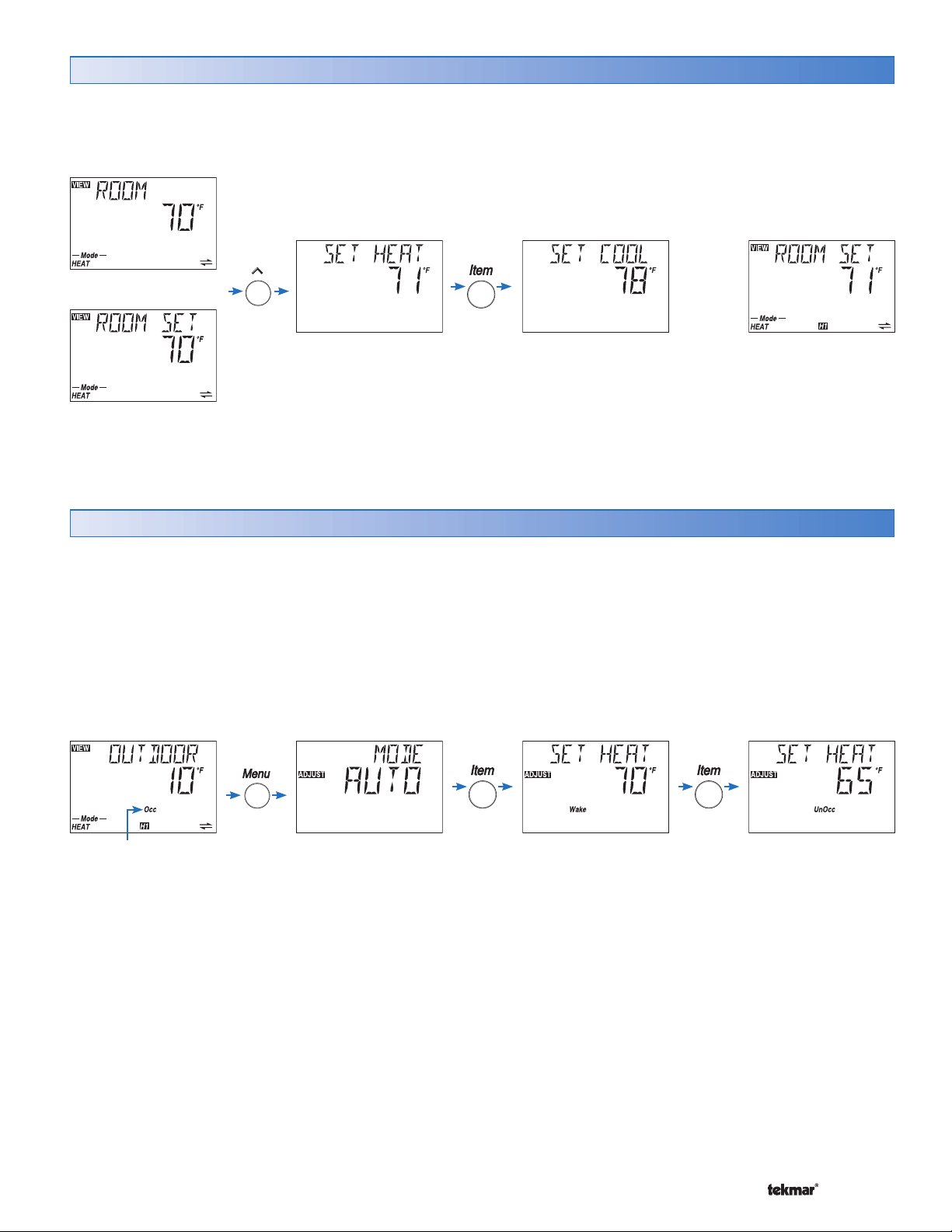
Adjusting the Room Set Temperature (No Schedule) Section C1
If no schedule is being used, the heating and cooling temperature can be permanently adjusted from the View menu
when viewing either the “Room” or “Room Set” items.
Wait 10
OR
seconds
Press Up or Down
Button to adjust the
heating temperature.
Press Up or Down
Button to adjust the
cooling temperature.
Adjusting the Room Set Temperature (Schedule) Section C2
When using a schedule, the heating and cooling temperature
for each schedule event can be permanently changed from
the Adjust menu. There will be one “Set Heat” and one “Set
Cool” item in the Adjust menu for each scheduled event.
In a two event schedule, the events are:
Occ (Occupied)• UnOcc (UnOccupied)•
In a four event schedule, the events are:
Wake
•
UnOcc
•
Occ
•
Sleep
•
When scenes are used, an additional ‘Away’ event is
available.
If a schedule is not in use, only the Set Heat Occ and Set
Cool Occ settings are available.
Current schedule
status indicates a
schedule is in use
21 of 36 © 2008 D 544 - 07/08
Press Up or Down
Button to adjust
the heating “Wake”
temperature.
Press Up or Down
Button to adjust the
heating “UnOcc”
temperature
Page 22
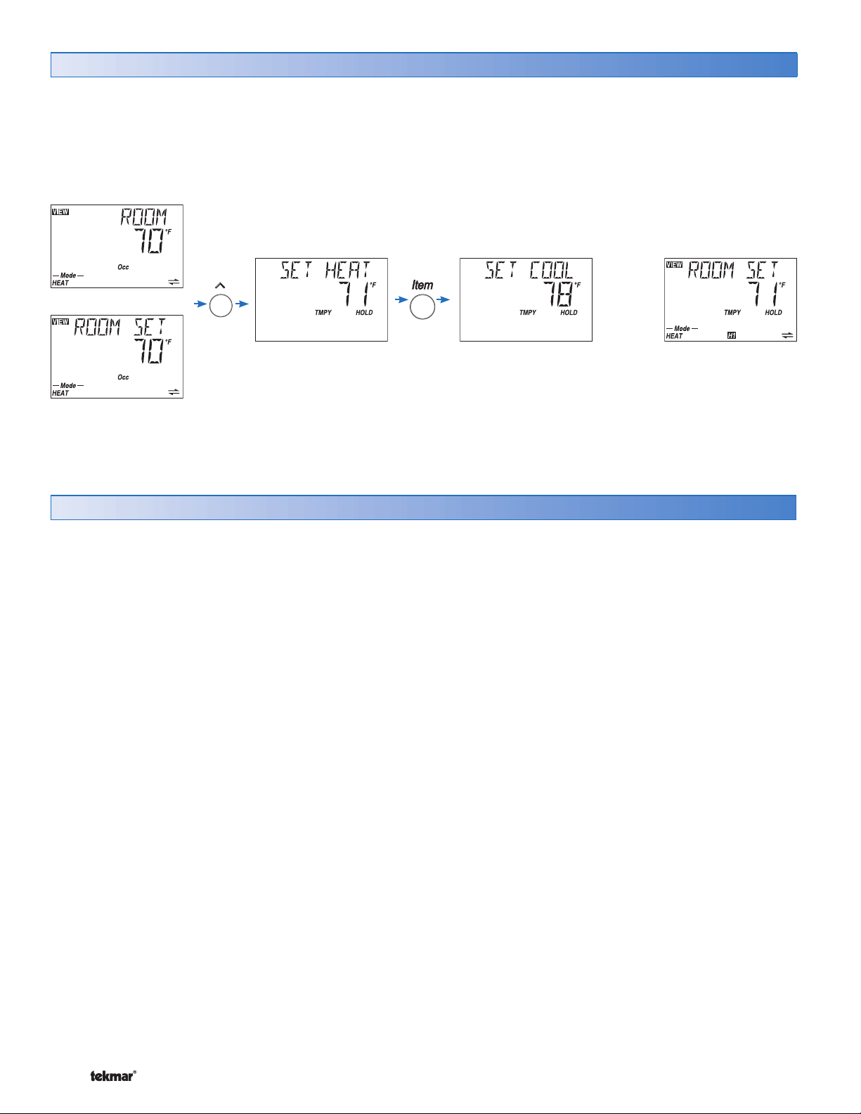
Temporary Room Set Adjustment (Schedule Only) Section C3
Pressing the up or down button while viewing the Room
or Room Set temperature during scheduled operation
allows for a temporary change in temperature. When the
temporary change is in effect, the words “TMPY HOLD”
are shown on screen.
OR
By default, the temporary change lasts for 3 hours. This
duration can be changed by going to the “Temporary Zone
Hold” item in the Scene menu.
The temporary change can be cancelled before it expires
by pressing the Up and Down buttons at the same time.
Wait 10
seconds
Cycles Per Hour Section D
You can set the number cycles per hour (CPH) for both
the heating and cooling operations. The default setting for
heating cycles per hour is automatic.
Heating CPH:
• When the thermostat is connected to a tN4 System
Control, the thermostat uses the CPH setting on the
tN4 System Control for the Heating CPH.
• To manually set the cycles per hour when the thermostat
is not connected to a tN4 System Control, go to the
Adjust menu and select the Heat CPH item.
• When the thermostat is connected to a tN4 system with
only thermostats, the SYNC setting synchronizes the
operation of all the thermostats to 5 CPH.
Cooling CPH:
The default setting for cooling cycles per hour is
automatic.
• To manually set the cycles per hour, go to the Adjust
menu and select Cool CPH.
Fan CPH:
• The fan cycles per hour is tied to the cooling cycles
per hour. When cooling is not used, the fan then uses
1 CPH.
© 2008 D 544 - 07/08 22 of 36
Page 23
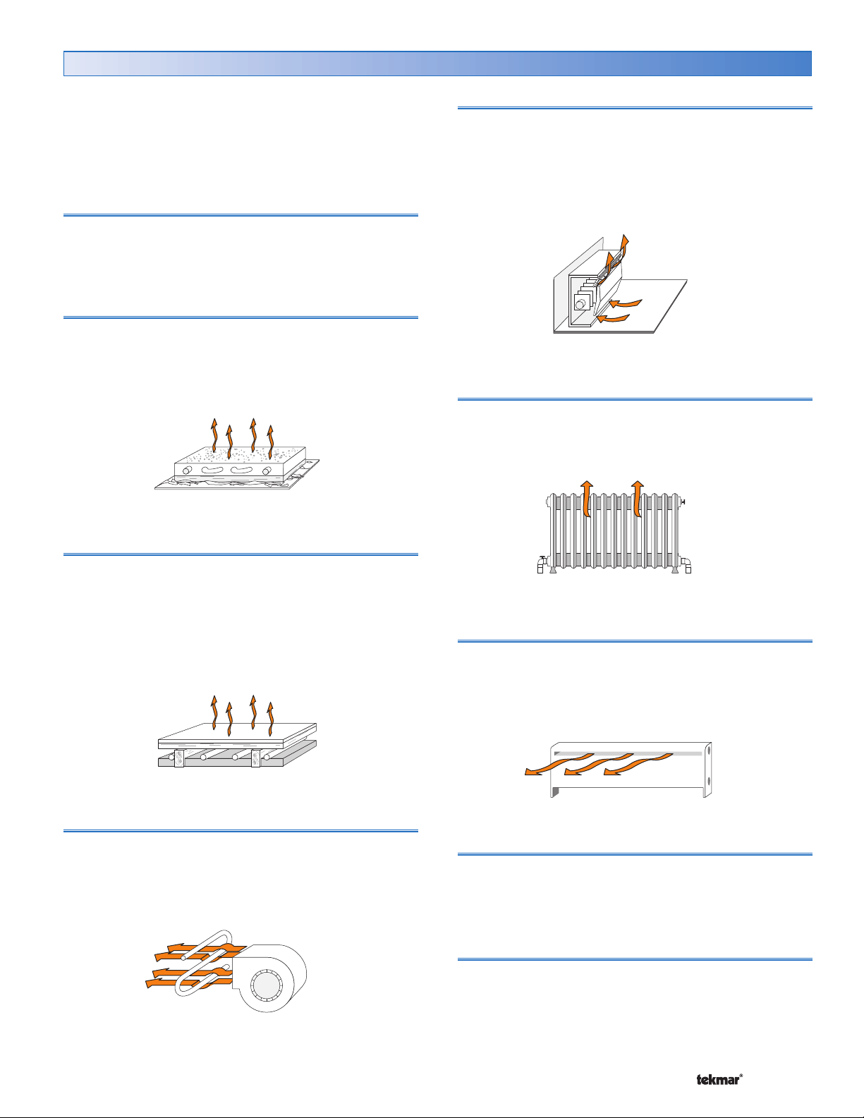
Heating Terminal Units Section E
This thermostat supports Outdoor Reset characterized
heating curves when used in hydronic heating systems. By
setting the correct terminal unit setting, the thermostat can
improve the operation of the heating system. Each stage
of heat has its own terminal unit setting.
Control (CTRL)
Selecting Control as the terminal unit setting on the thermostat
causes the thermostat to adopt the tN4 System Control’s
terminal unit setting.
Hydronic Radiant Floor 1 (HRF1)
Terminal type for a heavy, or high mass, hydronic radiant floor
system. This type of a hydronic radiant floor is embedded in
either a thick concrete or gypsum pour. This heating system
has a large thermal mass and is slow acting.
Fin–tube Convector (CONV)
A convector terminal unit is made up of a heating element
with fins on it. This type of terminal unit relies on the natural
convection of air across the heating element to deliver
heated air into the space. The amount of natural convection
is dependant on the supply water temperature to the heating
element and the room air temperature.
Radiator (RAD)
A radiator terminal unit has a large heated surface that is
exposed to the room. A radiator provides heat to the room
through radiant heat transfer and natural convection.
Hydronic Radiant Floor 2 (HRF2)
Terminal type for a light, or low mass, hydronic radiant
floor system. Most commonly, this type of radiant heating
system is either attached to the bottom of a wood sub floor,
suspended in the joist space, or sandwiched between the
subfloor and the surface. This type of radiant system has
a relatively low thermal mass and responds faster than a
high mass system.
Fancoil (COIL)
A fancoil terminal unit or air handling unit (AHU) consists
of an hydronic heating coil and either a fan or blower. Air
is forced across the coil at a constant velocity by the fan or
blower and is then delivered into the building space.
Baseboard (BASE)
A baseboard terminal unit is similar to a radiator, but has
a low profile and is installed at the base of the wall. The
proportion of heat transferred by radiation from a baseboard
is greater than that from a fin-tube convector.
Other (OTHR)
In applications where a non-hydronic heating system
(furnace, electric baseboard, etc.) is installed, set the
terminal unit to other.
Furnace (FURN)
When you are operating a furnace, or similar equipment,
and require the fan to operate with the heat relay contact,
set the terminal unit to furnace.
23 of 36 © 2008 D 544 - 07/08
Page 24
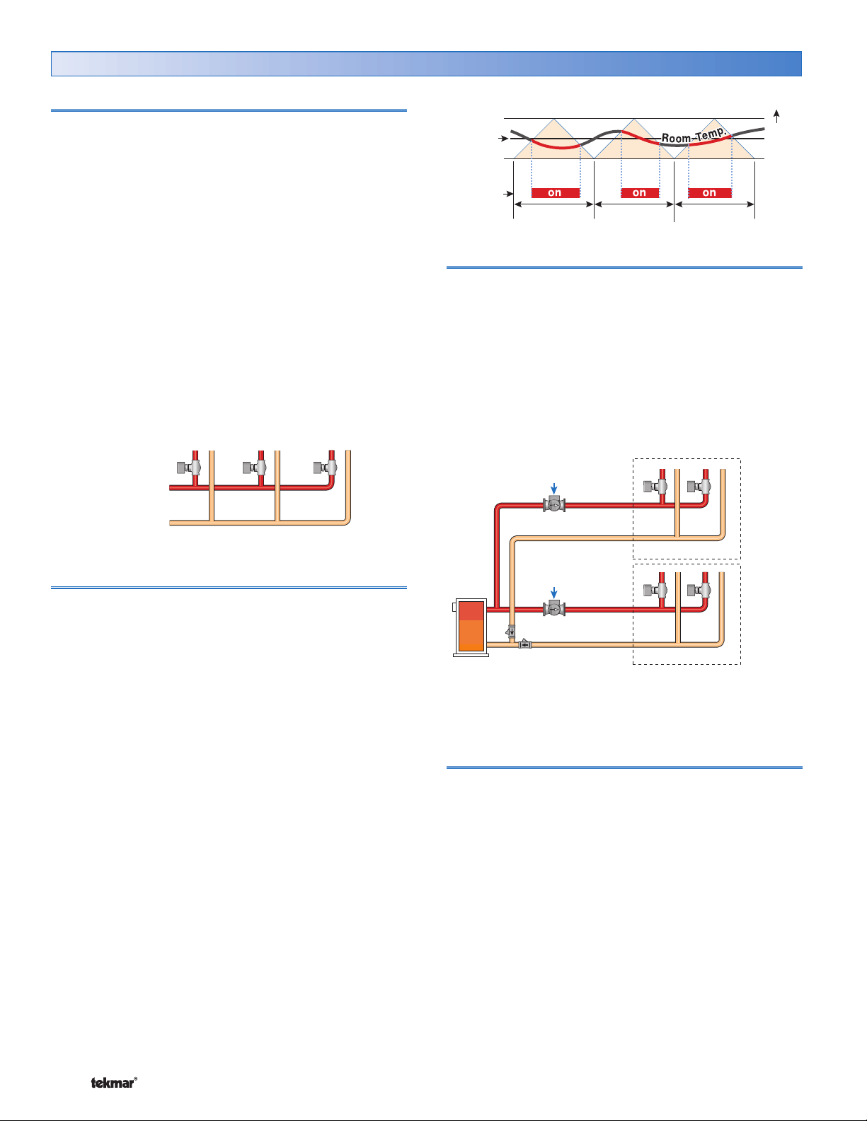
Heating Operation Section F
Indoor Temperature Feedback
Indoor feedback applies when the thermostat is connected to
a tN4 network with a tN4 System Control. Indoor temperature
feedback fine tunes the water temperature of the system
based on the requirements of the thermostats.
Each thermostat tells the tN4 System Control the water
temperature that it requires to heat its zone.
• If the zone is becoming too cool, the thermostat asks
for a higher water temperature.
• If the zone is becoming too warm, the thermostat asks
for a cooler water temperature.
The tN4 System Control provides the highest water
temperature required by all of the thermostats.
• The thermostat with the highest water temperature
requirement stays on 100% of its cycle.
• The remaining thermostats stay on for a percentage of
their cycles.
100%
On Time
Reset Water
Temperature
85%
On Time
90%
On Time
One-Stage PWM Heating
Set
Heat
Warmer
Heat
Cycle Length
System Pump Operation
When a tN4 System Control is used, each tN4 bus has a
system pump.
• If the tN4 bus’s system pump must turn on when the
Heat 1 relay is on, set the H1 Pump setting in the Adjust
menu to On.
Heat 1 Pump = OFF
Zone Manager: Zone Group DIP = On
Operated by
Zone Manager
One Stage Heating
Room Sensor Only
When operating with only an room sensor, the on time for
the Heat 1 relay is calculated to satisfy the requirements
of the room sensor.
Floor Sensor Only
When operation with only a floor sensor, the on time for
the Heat 1 relay is calculated to satisfy the requirements
of the floor sensor. The floor temperature varies between
the floor minimum and the floor maximum settings.
Note: Operation with only a floor sensor can lead to either
overheating or underheating of the space.
Room and Floor Sensor
When operating with both a room and floor sensor, the
thermostat calculates an on time for the Heat 1 relay to
satisfy the floor sensor and an on time to satisfy the room
sensor. The Heat 1 relay operates for the longer of these
two on times.
During light heating loads, overheating can occur due to
the minimum floor temperature setting.
During heavy heating loads, the maximum floor temperature
setting limits the on time of the Heat 1 relay. In this situation,
underheating can occur.
Zone Group
Operated by
tN4 System Control
Zone Group
Heat 1 Pump = On
Zone Manager: Zone Group DIP = OFF
Thermal Motor Zone Valves
When using a thermal motor zone valve, system pump
operation must be delayed to allow the thermal motor zone
valve to fully open.
• When thermal motor zone valves are used set the Heat
1 Delay setting to On.
© 2008 D 544 - 07/08 24 of 36
Page 25
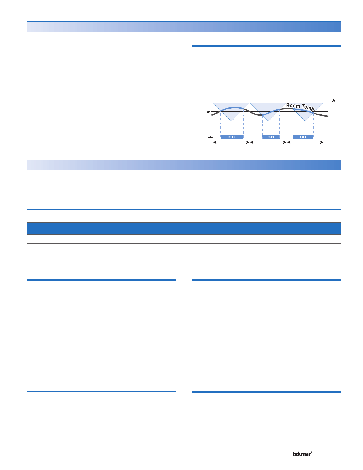
Cooling Operation Section G
The thermostat has one cooling contact.
For one stage cooling systems, use the Cool 1 contact to
operate the cooling equipment.
• Locate the COOL STG setting in the Adjust menu to set
the number of cooling stages.
One Stage Cooling
During each cooling cycle, the thermostat calculates a
required on time for the Cool 1 relay to satisfy the cooling
requirements of the zone.
• If more cooling is required, the on time is increased.
• If less cooling is required, the on time is decreased.
Heating / Cooling Interlock and Priority
To prevent frequent changes between heating and cooling,
use the Heating / Cooling Interlock setting. When the Mode
is set to Automatic, the thermostat waits for the interlock
time before switch over occurs.
• Locate the Interlock item in the Adjust menu
One-Stage PWM Cooling
Set
Cool
Cool
Cycle Length
Fan Operation Section H
The thermostat has a Fan contact that supports a wide
range of fan applications. Set the Fan Mode to determine
when the fan relay activates.
Fan Mode
There are three modes of operation that determine the operation of the Fan contact.
See the Fan Mode table for details.
• Locate the Fan Mode item in the Adjust menu.
Warmer
Fan Mode Fan 1 Contact operates together with… Description
None Dedicated Ventilation Dedicated Ventilation.
1 Cool Fan runs for Cooling.
2 Heat and Cool Fan runs for Heat and Cool.
Dedicated Ventilation
A dedicated ventilation system has a fan dedicated for
ventilation only. This is also common when using Heat
Recovery Ventilation (HRV) or Energy Recovery Ventilation
(ERV). Use the Fan contact to operate dedicated ventilation
fans. Fan Mode None must be selected when using
dedicated ventilation.
• Locate the Fan Mode item in the Adjust menu and set
to None.
• Locate the F1 Vent item in the Adjust menu and set
to On.
• Locate the Fan item in the Adjust menu for each event
(Wake, Unoccupied, Occupied, Sleep) and set the fan
operating percentage.
Ventilation Pre-vent
When the building is Unoccupied or in a Sleep period,
ventilation may be reduced or set to Off. As a result, stale
air may build up in the building. When transitioning to a
Wake or Occupied period, the dedicated ventilation may
be run continuously for a period of time to introduce fresh
air into the building.
• Locate the Ventilation Pre-vent item in the Adjust menu.
Intermittent Fan
The intermittent fan operation ensures the Fan contact
operates for a minimum percentage of each cycle. This
allows the fan to circulate air throughout the building.
The fan operates based upon the Fan Mode selected. If
the heating or cooling systems are shut off and the fan
has not yet met the minimum percentage on time, the fan
continues to run.
Intermittent Fan and Dedicated Ventilation cannot be used
at the same time.
• Locate the Fan item in the Adjust menu for each event
(Wake, Unoccupied, Occupied, Sleep) and set the
minimum fan operating percentage.
Fan Operation During Heating
The Fan contact operates during heating when both of the
following settings are made.
• Fan Mode must be set to 2.
and
• H1 terminal unit must be set to either Coil or Furnace.
25 of 36 © 2008 D 544 - 07/08
Page 26
Fan Pre and Post Purge
•
•
• •
• •
• •
•
•
•
•
•
To prevent the fan from operating before the coil reaches
the proper temperature, the operation of the fan can be
delayed. Likewise the operation of the fan may continue
after the heating or cooling has been completed.
• All fan settings are found in the Adjust menu.
• During a call for heating, the fan turns on after the Fan
Delay time expires.
• After heating or cooling, the fan turns off after the Fan
Purge time expires.
Time Clock Section I
The thermostat has a built-in time clock to allow the
thermostat to operate on a schedule. A battery-less backup
allows the thermostat to keep time for up to 4 hours without
Daylight Saving Time (DST) once the day, month, and year
are entered. Use the Time menu to set the correct time,
day, month, and year.
power. The time clock supports automatic adjustment for
Daylight Savings Time Modes
Mode DST Start DST End
1 1st Sunday in April Last Sunday in October
2 2nd Sunday in March 1st Sunday in November
Setting the Schedule Section J
To provide greater energy savings, you can operate the
thermostat on a programmable schedule. The schedule is
stored in memory and is not affected by loss of power to the
thermostat. A single thermostat zone or multiple devices
on the network can be assigned to follow the schedule of
one thermostat. On the 544, one schedule can be followed
for heating and for cooling.
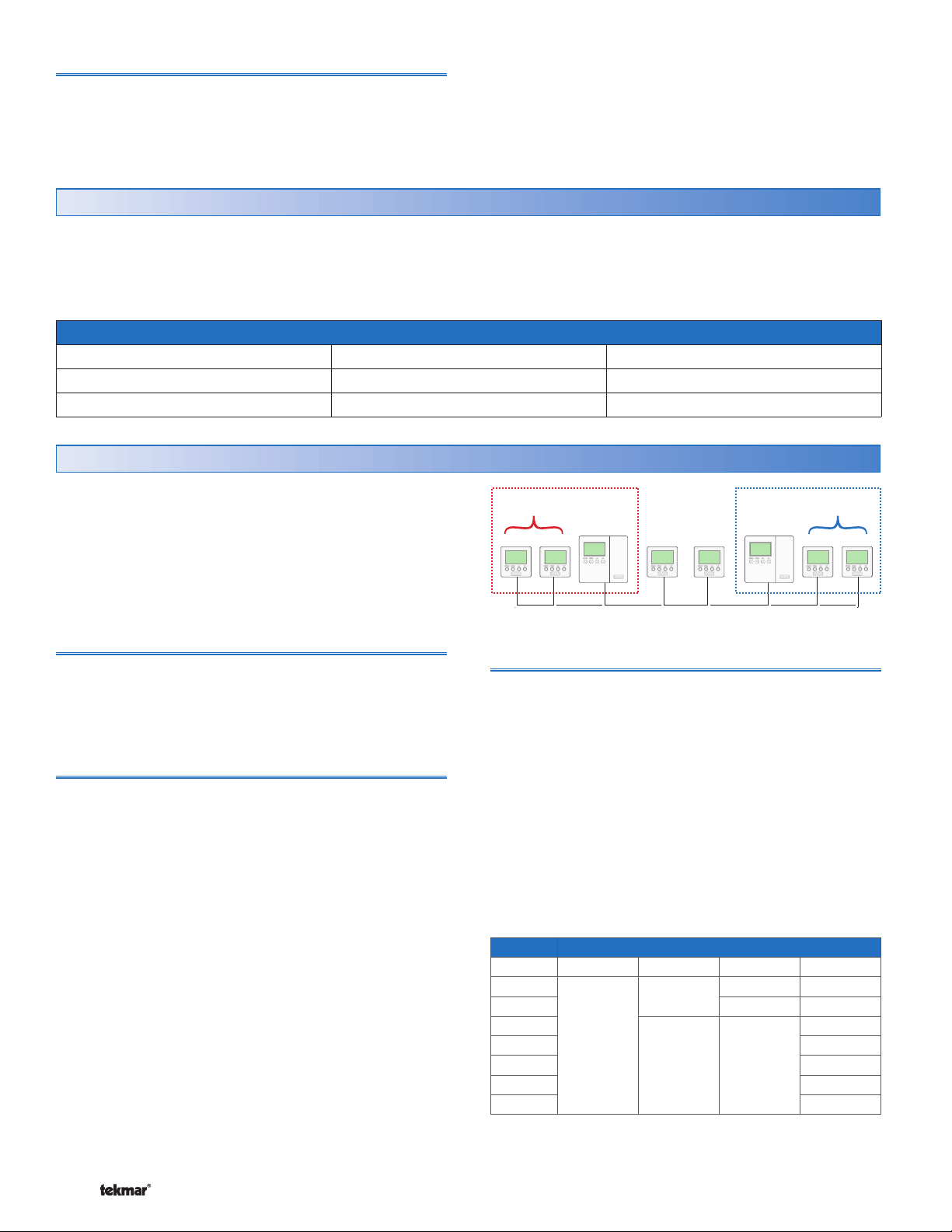
Zone Schedule
A zone schedule only applies to the thermostat on which
the schedule is programmed. The thermostat follows the
zone schedule and the events are not communicated to
other thermostats.
Master Schedule
If the thermostat is connected to other thermostats, then the
thermostat can operate on a master schedule. You can set
up a maximum of four master schedules on the tN4 network.
A master schedule is available to all devices on the tN4
network. Master schedules simplify installation since one
master schedule may be used by multiple devices.
To create a master schedule:
1. Assign a thermostat as a schedule master by setting
the HeatCool Schedule item in the Schedule menu to
Master (MST) 1 to 4.
To follow a master schedule
1. Assign a thermostat to follow a master schedule,
by setting the HeatCool Schedule menu item in the
Schedule menu to Member (MBR) 1 to 4.
Once a thermostat is the master schedule, a clock symbol
and number appear on the display in the View menu. The
number identifies the master schedule number. This helps
you locate the master schedule if you need to change the
schedule.
Members of
Schedule 1
Zone 1 2 3 4 5 6 7 8
Schedule Types
The schedule type determines when the schedule repeats
itself. This thermostat includes four schedule types:
• 24 Hour: Repeats every 24 hours.
• 5-2: Repeats on a weekly basis. However, it breaks the
week into the weekend and weekdays. This reduces the
amount of schedule event settings.
• 5-11: Repeats on a weekly basis. However, it breaks
the week into Saturday and Sunday followed by the
weekdays. This reduces the amount of schedule event
settings.
• 7 Day: Repeats on a weekly basis and allows for separate
event times for each day.
Day 24 Hour 5-2 5-11 7 day
Sa
Su
Mo
Tu
We
Th
Fr
Master
Schedule 1
None
Zone
Schedule
Schedule Type
Master
Schedule 2
Members of
Schedule 2
© 2008 D 544 - 07/08 26 of 36
Page 27
Schedule Mode Event 24Hr Sat Sun Mon Tue We Thu Fri
Wake
Unoccupied
6:00 AM 6:00 AM 6:00 AM 6:00 AM 6:00 AM 6:00 AM 6:00 AM 6:00 AM
8:00 AM 8:00 AM 8:00 AM 8:00 AM 8:00 AM 8:00 AM 8:00 AM 8:00 AM
4 events per day
Occupied
Sleep
6:00 PM 6:00 PM 6:00 PM 6:00 PM 6:00 PM 6:00 PM 6:00 PM 6:00 PM
10:00 PM 10:00 PM 10:00 PM 10:00 PM 10:00 PM 10:00 PM 10:00 PM 10:00 PM
or
Occupied
6:00 AM 6:00 AM 6:00 AM 6:00 AM 6:00 AM 6:00 AM 6:00 AM 6:00 AM
2 events per day
Unoccupied
10:00 PM 10:00 PM 10:00 PM 10:00 PM 10:00 PM 10:00 PM 10:00 PM 10:00 PM
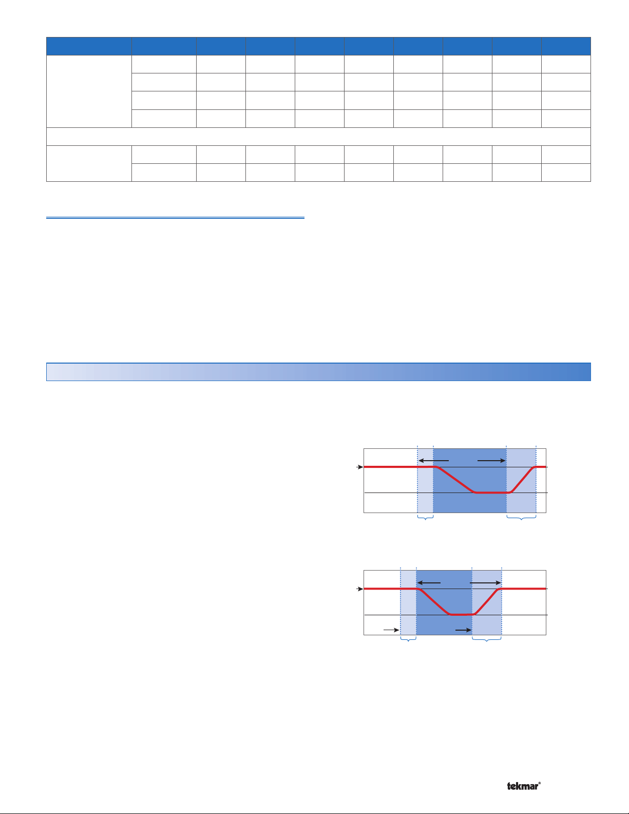
Schedule Mode
The schedule mode can have either 4 or 2 events per day.
An event is a time at which the thermostat changes the set
temperature. The event time can be set to the nearest 10
minutes. If you wish to have the thermostat skip the event,
enter “--:--“ as the time. The “--:--“ time is found between
11:50 PM and 12:00 AM. See the table, Schedule Mode,
for more details regarding types of events.
Optimum Start / Stop Section K
When using a schedule, there is a time lag as one event
transitions to another. The four possible transitions are:
• Wake to Unoccupied
• Unoccupied to Occupied
• Occupied to Sleep
• Sleep to Wake
When an outdoor temperature measurement is available,
the Optimum Start / Stop feature predicts how long the
temperature transition takes. This allows the thermostat to
operate the heating or cooling system before the scheduled
event in order to have the room at the desired temperature
at the scheduled event time.
When an outdoor temperature measurement is not
available, then the Optimum Start / Stop feature operates
slightly differently. First, the thermostat predicts how long
the transition takes when changing from a low temperature
to a high temperature. It does not track transitions where
the temperature setting drops from a high temperature to
a low temperature. When cooling, the cooling system is
allowed to turn on 30 minutes prior to the beginning of a
period that requires cooling.
• Locate the Optimum Start / Stop setting in the Adjust
menu.
Room
Tem p.
Room
Tem p.
Optimum
Stop
Without Optimum Start/Stop
10P.M. 11 P.M. 8A.M. 11A.M.
Setback
Period
Delay Period
Optimum Start/Stop
9P.M. 10P.M. 5A.M. 8A.M.
Setback
Period
Optimum
Start
Delay Period
Recovery Period
Recovery Period
Occ
70°F (21°C)
UnOcc
65°F (18°C)
Occ
70°F (21°C)
UnOcc
65°F (18°C)
27 of 36 © 2008 D 544 - 07/08
Page 28
Scenes Section L
Scenes are a function that is available on the thermostat.
• To use the scene function, go to the Scene menu and
set the Scene setting to On.
Scenes are a method of changing the temperature throughout
an entire building from a single thermostat. A permanent
scene remains in place until another scene is selected.
When a temporary scene is selected (Scenes 6, 7, 8), a
timer counts down and when it times out, devices return
to the last permanent scene selected.
See the Scene table for details regarding the timing of
Scenes. There are a total of eight Scenes available.
• Default Scene: The default scene is Permanent 1. In a
typical installation, the thermostat will be set to follow
the scheduled event in the Permanent 1 scene.
• Factory Set Scenes: Scenes 2, 3 and 6 are factory set
and force the thermostat to the Away, Unoccupied or
the Occupied temperature respectively.
• Customizable Scenes: You can customize Scenes 1, 4,
5, 7, and 8 to either follow the scheduled event, or the
temperature can be forced to the Wake, Unoccupied,
Occupied, Sleep, or the Away temperature.
Note: If no schedule is available, the Scene menu selections
are limited to Occupied and Away
Scene Description Thermostat Operation
1 Permanent 1 Scheduled event, Wake, Unoccupied, Occupied, Sleep, Away
2 Permanent Away 2 Away
DHW demands are ignored (applies to outdoor reset modules)
Setpoint demands operate (applies to outdoor reset modules)
3 Permanent Unoccupied 3 Unoccupied
4 Permanent 4 Scheduled event, Wake, Unoccupied, Occupied, Sleep, Away
5 Permanent 5 Scheduled event, Wake, Unoccupied, Occupied, Sleep, Away
6 Temporary Occupied 6 Occupied for 3 hours
7 Temporary 7 Scheduled event, Wake, Unoccupied, Occupied, Sleep, Away for 4 hours
8 Temporary 8 Scheduled event, Wake, Unoccupied, Occupied, Sleep, Away for 8 hours
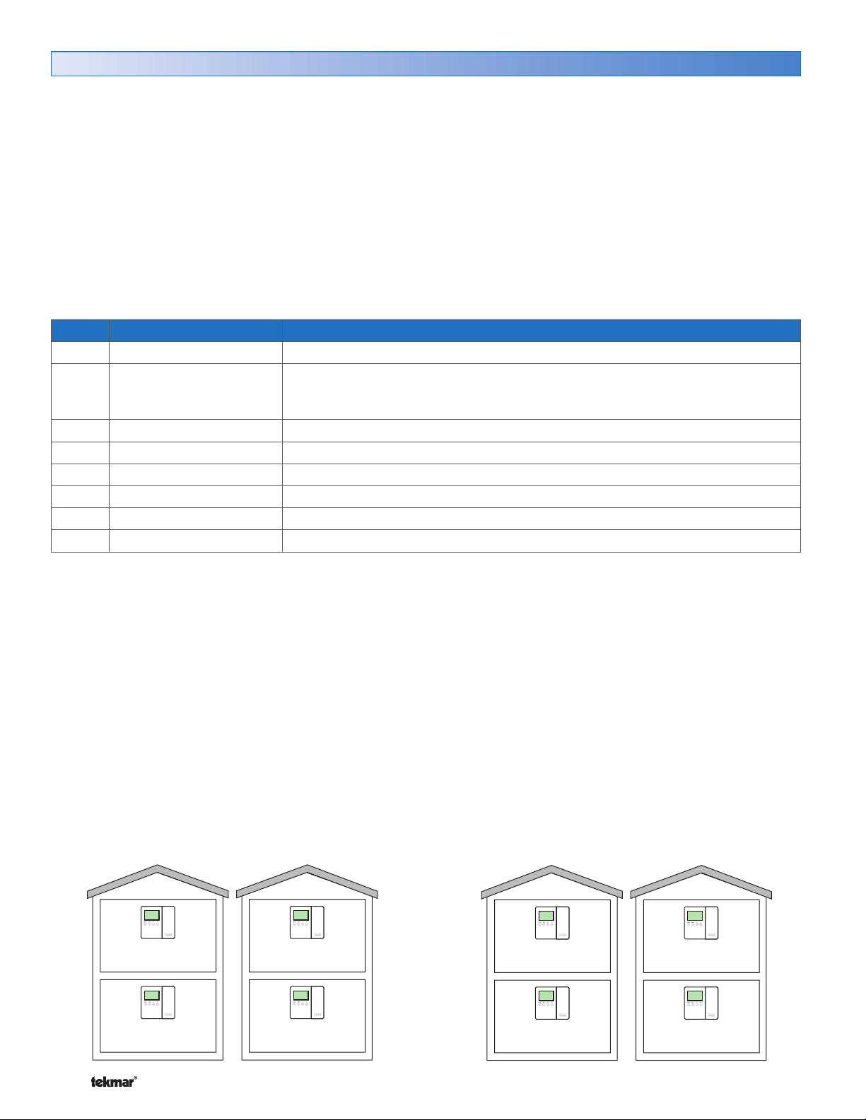
Example 1:
A house is normally in scene Permanent 1. There is a
master bedroom that operates on a schedule and there is
a guest bedroom that is normally set to Unoccupied. When
a guest arrives, the scene changes to Permanent 4. Scene
4 has been pre-programmed to change the guest room to
operate on the schedule.
Master bedroom thermostat:
Scene Permanent 1 is set to Schedule.
Scene Permanent 4 is set to Schedule.
Guest bedroom thermostat:
Scene Permanent 1 is set to Unoccupied.
Scene Permanent 4 is set to Schedule.
Scene 1
70°F
Master Bedroom
Scheduled Event
Scene 4
70°F
Master Bedroom
Scheduled Event
Example 2:
A house is normally in scene Permanent 1. There are
bedrooms upstairs and the entertainment area is downstairs.
The occupants are entertaining guests for an evening and
scene Temporary 7 is selected. This causes the upstairs
thermostats to operate at the Unoccupied temperature and
the downstairs to operate and the Occupied temperature
for four hours.
Upstairs thermostats:
Scene Permanent 1 is set to Schedule.
Scene Temporary 7 is set to Unoccupied.
Downstairs thermostats:
Scene Permanent 1 is set to Schedule.
Scene Temporary 7 is set to Occupied.
Scene 1
70°F
Upstairs
Scheduled Event
Scene 7
62°F
Upstairs
UnOccupied
for
4hr
62°F
Guest Bedroom
UnOccupied
© 2008 D 544 - 07/08 28 of 36
Guest Bedroom
Scheduled Event
70°F
70°F
Downstairs
Scheduled Event
70°F
Downstairs
Scheduled Event
Page 29
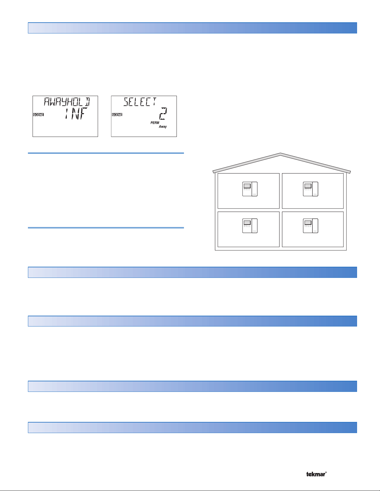
Away Hold Section M
To set the temperature while the occupants are away, use the
Permanent Away 2 scene. This scene changes all thermostats
on the network to the Away temperature setting. If there is
an Outdoor Reset Module on the tN4 communication bus,
the boiler no longer responds to domestic hot water calls
for heat. Setpoint demands continue to operate as in the
Occupied mode.
Away Temperatures
An Away temperature setting exists for both heating and
cooling. By default, the Set Heat Away temperature is set
to 62°F (16.5°C) and the Set Cool Away temperature is
set to 85°F (29.5°C).
• To set the Away temperature, go to the Adjust menu
and select the Set Heat Away and the Set Cool Away
items. The Access Level must be set to Installer or
Advanced.
• To set the number of days away, go to the Scene menu
and select Away Hold.
When set to Infinite, the Permanent Away 2 scene remains
until a new scene is selected. If you know in advance how
long the building occupant will be away, you can adjust Away
Hold to the number of days. Once the number of days have
elapsed, the thermostat automatically changes from the
Permanent Away 2 scene to previous permanent scene.
Example: The home occupants are traveling for 14 days.
They want the home to be at the Away temperatures
for 14 days and then automatically return to the normal
schedule.
• Away Hold is set to 14 days.
• Scene is changed to Permanent Away 2.
62°F
Away Away
62°F
Length of Time Away
The Away Hold feature allows you to set the number of
62°F
Away Away
62°F
days the Away temperature applies.
Offset Section N
This thermostat uses a high quality temperature thermistor
and is calibrated to accurately read the room temperature.
However, if you wish to fine tune the measured room
temperature, use the Offset feature to increase or decrease
room temperature in tenths of degrees.
• Locate the Offset setting in the Misc menu.
Warm Weather Shut Down Section O
The Warm Weather Shut Down (WWSD) feature prevents
the heating system from operating after the outdoor
temperature exceeds the WWSD temperature setting. You
can follow the tN4 System Control’s WWSD or you can set
WWSD temperatures for the Wake and Occupied events,
and for the Unoccupied and Sleep events. You can also
enable or shut off floor warming depending on changes in
outdoor temperatures.
• Locate the WWSD setting in the Adjust menu.
Units of Temperature Section P
The thermostat can display temperatures in either
Fahrenheit (°F) or in Celsius (°C).
• Locate the units setting in the Misc menu.
Backlight Section Q
Use the thermostat’s backlight to increase the visibility of
the display. You can set the backlight to On, Temporary,
or Off. If you select On, the backlight remains permanently
on. If you select Temporary, the backlight comes on for 30
29 of 36 © 2008 D 544 - 07/08
seconds when a button is pressed. If you select Off the
backlight remains permanently off. By default, the backlight
is set to Temporary.
• Locate the Backlite setting in the Misc menu.
Page 30

tN4 Address Section R
When connected to other tN4 devices through a tN4 bus,
the thermostat is automatically assigned a network address.
The tN4 address is useful when trying to correct bus error
open and short circuits.
The address includes the bus water temperature designation
and a device number. The bus water temperature designations
available are Boiler, Mix 1, Mix 2, etc. The device number
can range from 1 to 24. If the thermostat is operating as a
member of a thermostat-only network, the thermostat does
not have an address and the address item in the MISC
menu is not available.
The device number determines the heating priority for each
zone. A thermostat with device number 1 has a higher priority
than device number 24. The tN4 address allows the tN4
system control to shut off low priority zonezs when the heat
source is unable to heat all zones simultaneously. In some
cases, the installer may want to change the thermostat’s
address in order to change the thermostat’s priority relative
to other thermostats.
Note: Keep track of manually set tN4 addresses. When
a tN4 address is manually set, tN4 thermostats using the
Auto Address setting will automatically be assigned new
addresses.
If two thermostats are manually set to the same address, an
error message will appear. The error remains until one of
the addresses is manually changed to a vacant address.
Pump Exercising Section S
When connected to a tN4 system control, the thermostat
exercises the pump relays for 10 seconds every 3 days.
Exercising helps prevent pump seizure. While the thermostat
is exercising, the display shows “Test”.
Exercising does not occur when:
• Mode of Operation is set to Off.
• Heat Source is set to Other.
• DIP switch 2 is set to None.
© 2008 D 544 - 07/08 30 of 36
Page 31
Error Messages
Local Errors and Device Errors
Error messages are used to indicate a problem somewhere in the system. There are two types of error messages: Local
Errors and Device Errors.
A Local Error indicates an error specific to a device. For example, a thermostat with a sensor short circuit will show a Sensor
Short Error on its display. No other devices will show this specific error (unless they also have a sensor short circuit).
A Device Error is used to indicate that there is a local error somewhere else on the system. For example, if a thermostat
has a sensor short circuit, that thermostat will show a Local Error indicating specifically what the problem is. All other
devices on the network will show Device Errors, indicating the address of the device with the Local Error. In other words,
Device Errors are nothing more than pointers, showing you that there is a local error somewhere on the system and where
to find it.
Error Priority
Only one error can be shown on a particular device at a time. If there is more than one error on the system, the highest
priority error will be the one that is shown. The table on pages 37 and 38 lists error messages in order of high priority to
low priority.
How to Locate an Error Message
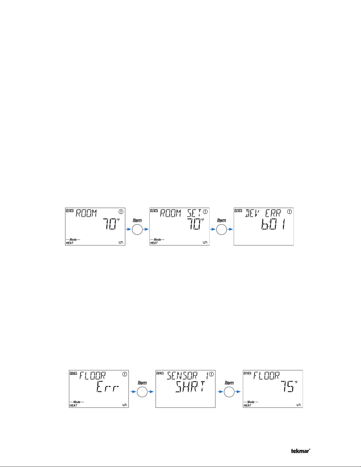
If the warning symbol (flashing circle with exclamation mark) is visible on screen, this indicates that there is an error
somewhere on the system. To view the error message, you must first put the control into the Advanced or Installer access
level (available in MISC menu). When an error message is present, it is available as an item in the VIEW menu.
While in the View Menu, press the item button until the error message is displayed. You may have to advance through
several View Menu items before the message is displayed.
If the error message is a Device Error (if “DEV” or “DEV ERR” is shown on screen), read the address shown and go to the
device with that address. That device will have a Local Error indicating specifically what the problem is. When the problem
is corrected, the error message will automatically clear.
Access Levels
In some cases, it is not desirable to let day-to-day users view error messages. In these cases, by lowering the access level
of the thermostat or setpoint device to ‘User’ or lower, error messages cannot be seen in the View menu and the warning
symbol only appears if there is a local error or a device error caused by a critical error on another device. If there is an error
message on the system that you cannot find on a particular thermostat, make sure that the access level on that thermostat
is set to Installer or Advanced.
Sensor Temperature Errors
If a control is unable to display a temperature due to a sensor malfunction or communication problem, the word “Err” is
displayed in place of the temperature. This usually indicates that there is an error somewhere on the system but is not the
actual error message. Keep looking through the View menu to find the actual error message.
Device is attempting to
show floor temperature
but cannot because of
sensor problem.
Keep pressing the Item
button to find the actual
error message
Once error is corrected,
the temperature can be
displayed
31 of 36 © 2008 D 544 - 07/08
Page 32
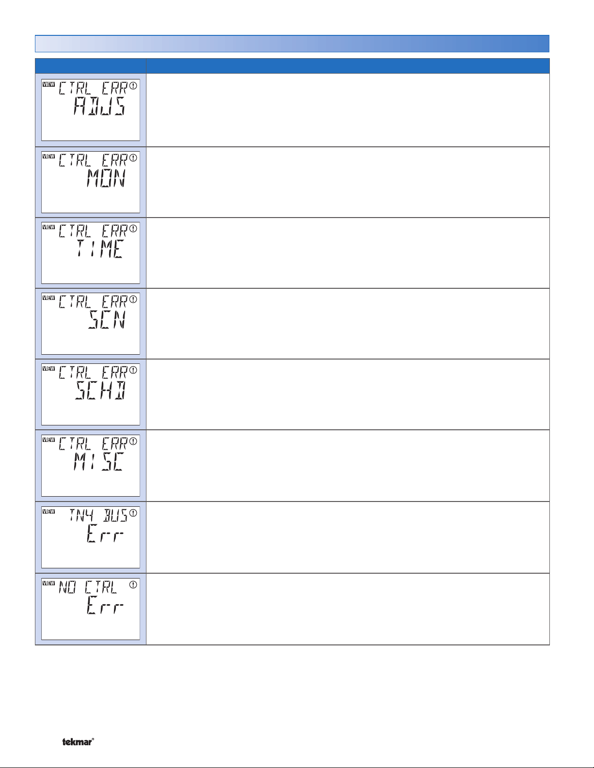
Error Messages (1 of 3)
Error Message Description
ADJUST ERROR
The thermostat failed to read the Adjust menu settings from memory and has reloaded
the factory default settings. Operation stops until you check the Adjust menu settings. The
thermostat provides freeze protection only until you check the Adjust menu items.
Note: To clear the error, the access level must be set to Advanced before checking the
settings in the Adjust menu.
MONITOR ERROR
The thermostat failed to read the Monitor menu settings from memory and has reloaded the
factory default settings. The thermostat continues to operate while displaying this error.
Note: To clear the error, the access level must be set to Advanced before checking the
settings in the Monitor menu.
TIME ERROR
The thermostat failed to read the Time menu settings from memory and has reloaded the
factory default settings. The thermostat continues to operate while displaying this error.
Note: To clear the error, the access level must be set to Advanced before checking the
settings in the Time menu.
SCENE ERROR
The thermostat failed to read the Scene menu settings from memory and has reloaded the
factory default settings. The thermostat continues to operate while displaying this error.
Note: To clear the error, the access level must be set to Advanced before checking the
settings in the Scene menu.
SCHEDULE ERROR
The thermostat failed to read the Schedule menu settings from memory and has reloaded the
factory default settings. The thermostat continues to operate while displaying this error.
Note: To clear the error, the access level must be set to Advanced before checking the
settings in the Schedule menu.
MISCELLANEOUS ERROR
The thermostat failed to read the Miscellaneous menu settings from memory and has reloaded
the factory default settings. The thermostat continues to operate while displaying this error.
Note: To clear the error, the access level must be set to Advanced before checking the settings
in the Miscellaneous menu.
tN4 BUS ERROR
Due to a short or open circuit, communication is lost with the tN4 bus. Check wires for damage.
Check ‘C’ and ‘R’ wires for polarity. All devices on the tN4 bus will display this error if there is a
short circuit. If the error is only on this device, check for an open circuit between the thermostat
and Zone Manager. Once the error is corrected press any button to clear the error.
NO tN4 SYSTEM CONTROL
The tN4 System Control DIP switch is set to tN4 System Control and the thermostat does
not detect the tN4 System Control. Once the tN4 System Control is detected, this error will
clear automatically.
Note: If a tN4 System Control is not installed, set the tN4 System Control DIP switch to None.
© 2008 D 544 - 07/08 32 of 36
Page 33
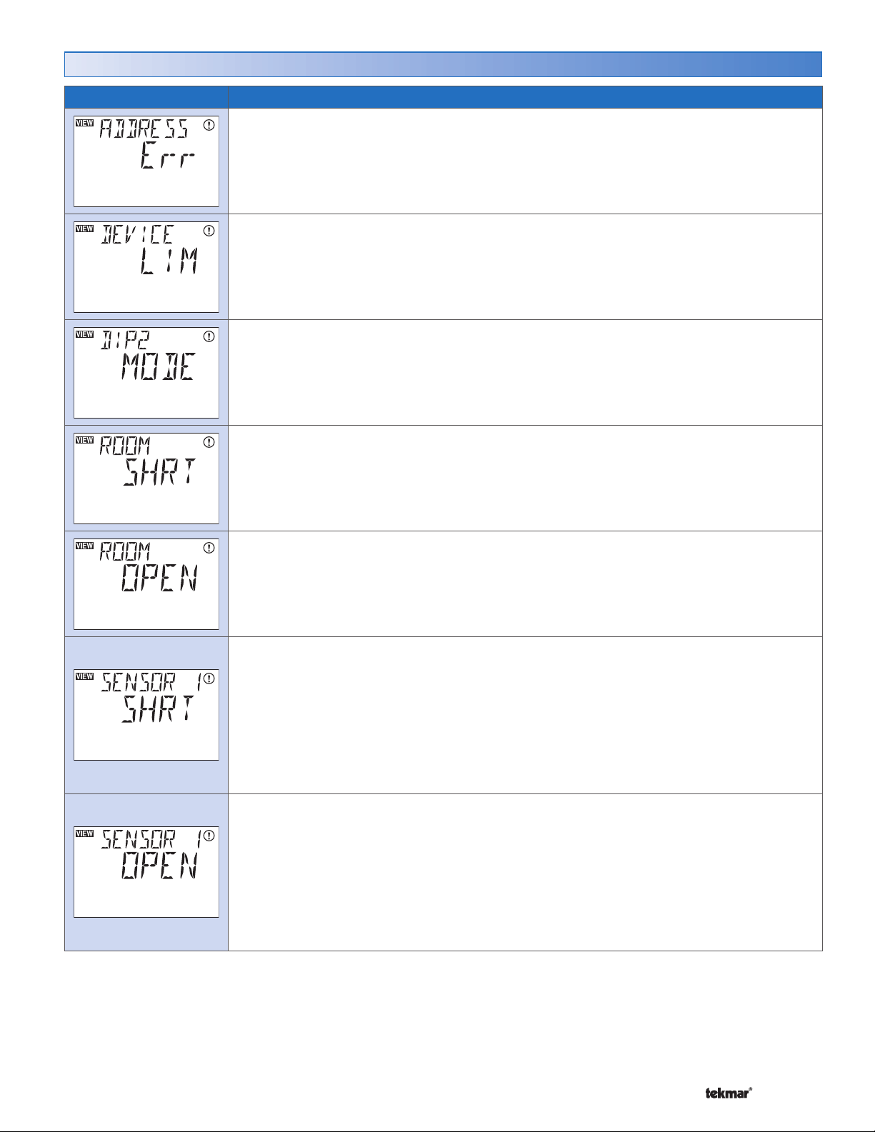
Error Messages (2 of 3)
Error Message Description
ADDRESS ERROR
Two thermostats have been manually set to the same address. The thermostat continues to
operate with this error but does not communicate with the tN4 bus. To clear this error select
an unused address. This can be done automatically by setting the Address item to Auto.
DEVICE LIMIT
You have installed more than 24 devices on the tN4 bus. You must remove the additional
devices and move them to a different bus if possible.
DIP SWITCH 2 MODE
The tN4 System Control DIP switch is set to None and the thermostat has detected a tN4
System Control. The thermostat does not operate until this error is corrected. The tN4 System
Control DIP switch must be set to tN4 System Control.
ROOM SENSOR SHORT CIRCUIT
Due to a short circuit, the thermostat failed to read the built-in sensor. If either Sensor 1 or 2 are
set to ROOM, or the thermostat is connected to a tN4 System Control, the thermostat continues
to operate. Otherwise, the thermostat stops operation. To clear the error, press either the
Menu or Item button. If the error does not clear, contact your tekmar sales representative.
ROOM SENSOR OPEN CIRCUIT
Due to an open circuit, the thermostat failed to read the built-in sensor. If either Sensor 1 or 2 are
set to ROOM, or the thermostat is connected to a tN4 System Control, the thermostat continues
to operate. Otherwise, the thermostat stops operation. To clear the error, press either the
Menu or Item button. If the error does not clear, contact your tekmar sales representative.
SENSOR 1 SHORT CIRCUIT
Due to a short circuit, the thermostat failed to read Sensor 1. The thermostat displays the
error and continues to operate unless:
No other Room sensors are available and the thermostat is not connected to a tN4 System
control. Then the thermostat stops operation.
No other Floor sensors are available and the Floor Maximum is not set to Off, then the H1
contact no longer operates.
Locate and repair the problem as described in the Data Brochure D 070. Once the error is
corrected, press any button to clear the error.
SENSOR 1 OPEN CIRCUIT
Due to an open circuit, the thermostat failed to read Sensor 1. The thermostat displays the
error and continues to operate unless:
No other Room sensors are available and the thermostat is not connected to a tN4 System
control. Then the thermostat stops operation.
No other Floor sensors are available and the Floor Maximum is not set to Off, then the H1
contact no longer operates.
Locate and repair the problem as described in the Data Brochure D 070. Once the error is
corrected, press any button to clear the error.
33 of 36 © 2008 D 544 - 07/08
Page 34
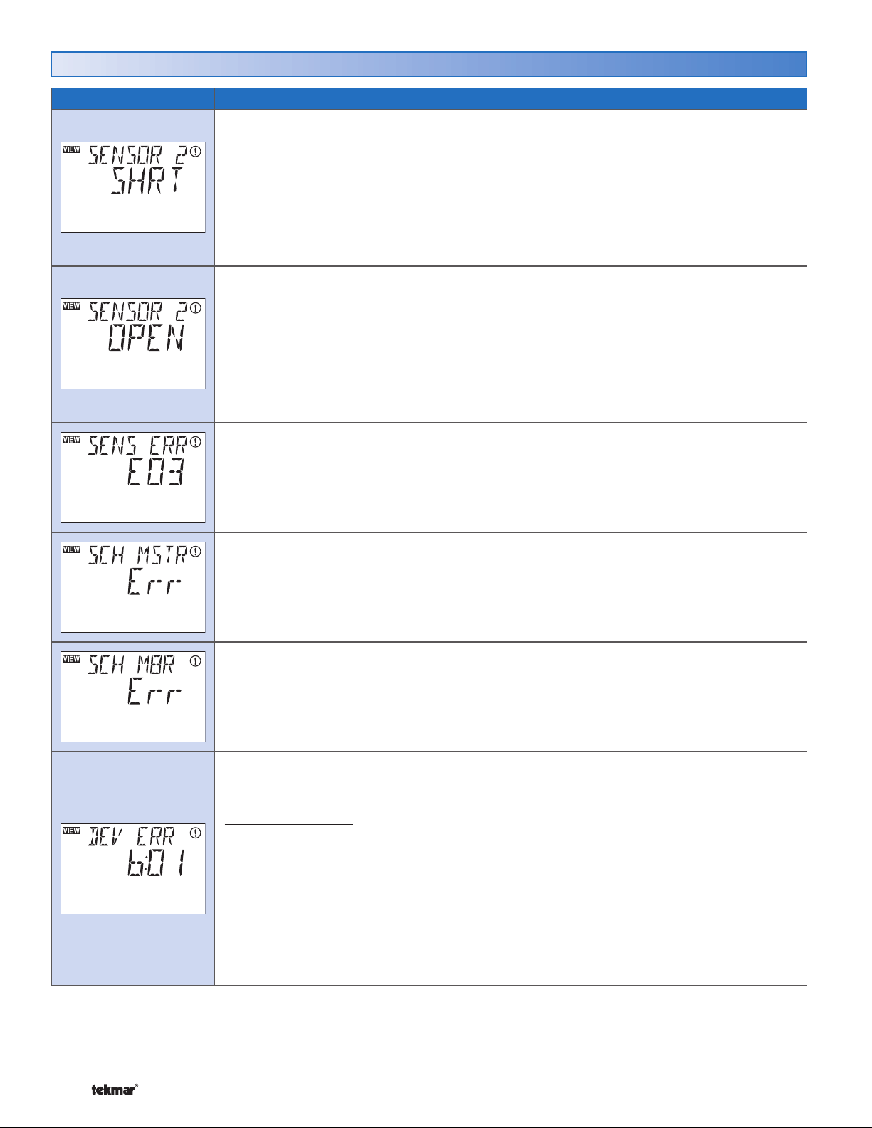
Error Messages (3 of 3)
Error Message Description
SENSOR 2 SHORT CIRCUIT
Due to a short circuit, the thermostat failed to read Sensor 2. The thermostat displays the
error and continues to operate unless:
No other Room sensors are available and the thermostat is not connected to a tN4 System
control. Then the thermostat stops operation.
No other Floor sensors are available and the Floor Maximum is not set to Off, then the H1
contact no longer operates.
Locate and repair the problem as described in the Data Brochure D 070. Once the error is
corrected, press any button to clear the error.
SENSOR 2 OPEN CIRCUIT
Due to an open circuit, the thermostat failed to read Sensor 2. The thermostat displays the
error and continues to operate unless:
No other Room sensors are available and the thermostat is not connected to a tN4 System
control. Then the thermostat stops operation.
No other Floor sensors are available and the Floor Maximum is not set to Off, then the H1
contact no longer operates.
Locate and repair the problem as described in the Data Brochure D 070. Once the error is
corrected, press any button to clear the error.
SENSOR ERROR
All of the sensors have been set to Off or None including the built-in sensor and the tN4
System Control DIP switch is set to None. The thermostat stops operation.
Turn on at least one sensor or connect the thermostat to a tN4 system control and set the
tN4 System Control DIP switch to tN4 System Control.
SCHEDULE MASTER ERROR
Two thermostats have been set to the same SCH MSTR setting. Select a different SCH MSTR
setting for the thermostat. The thermostat operates in the Occupied mode while this error
message is present. The error message clears automatically once the error is corrected.
SCHEDULE MEMBER ERROR
The thermostat can no longer detect its schedule master. Check the communication connections
for open or short circuits. Once the schedule master has been detected, the error message
clears.
DEVICE ERROR AT ADDRESS #:##
#:## is the address of the device with the error. The bus number displays before the colon,
and the device number displays after. Go to the device with the address displayed.
Possible Addresses:
01 to 24 - Device Error on Thermostat only network
b:01 to b:24 - Device Error on Boiler Bus
1:01 to 1:24 - Device Error on Bus 1
2:01 to 2:24 - Device Error on Bus 2
3:01 to 3:24 - Device Error on Bus 3
CTRL - Device Error on System Control
MIX1 - Device Error on Mixing Expansion Module (See System Control for local error)
MIX2 - Device Error on Mixing Expansion Module (See System Control for local error)
MIX3 - Device Error on Mixing Expansion Module (See System Control for local error)
© 2008 D 544 - 07/08 34 of 36
Page 35

Cleaning the Thermostat
The thermostats’s exterior can be cleaned using a damp cloth. Moisten the cloth with water and wring out prior to wiping
the control. Do not use solvents or cleaning solutions.
35 of 36 © 2008 D 544 - 07/08
Page 36
Limited Warranty and Product Return Procedure
Limited Warranty The liability of tekmar under this
warranty is limited. The Purchaser, by taking receipt
of any tekmar product (“Product”), acknowledges the
terms of the Limited Warranty in effect at the time of
such Product sale and acknowledges that it has read
and understands same.
The tekmar Limited Warranty to the Purchaser on the
Products sold hereunder is a manufacturer’s passthrough warranty which the Purchaser is authorized to
pass through to its customers. Under the Limited Warranty, each tekmar Product is warranted against defects
in workmanship and materials if the Product is installed
and used in compliance with tekmar’s instructions, ordinary wear and tear excepted. The pass-through warranty period is for a period of twenty-four (24) months
from the production date if the Product is not installed
during that period, or twelve (12) months from the documented date of installation if installed within twenty-four
(24) months from the production date.
The liability of tekmar under the Limited Warranty shall
be limited to, at tekmar’s sole discretion: the cost of parts
and labor provided by tekmar to repair defects in materials
and / or workmanship of the defective product; or to the
exchange of the defective product for a warranty replacement product; or to the granting of credit limited to the original cost of the defective product, and such repair, exchange
or credit shall be the sole remedy available from tekmar,
and, without limiting the foregoing in any way, tekmar is
not responsible, in contract, tort or strict product liability,
for any other losses, costs, expenses, inconveniences, or
damages, whether direct, indirect, special, secondary, incidental or consequential, arising from ownership or use of
the product, or from defects in workmanship or materials,
including any liability for fundamental breach of contract.
Any representations or warranties about the Products made
by Purchaser to its customers which are different from or in
excess of the tekmar Limited Warranty are the Purchaser’s
sole responsibility and obligation. Purchaser shall indemnify and hold tekmar harmless from and against any and all
claims, liabilities and damages of any kind or nature which
arise out of or are related to any such representations or
warranties by Purchaser to its customers.
The pass-through Limited Warranty does not apply if the
returned Product has been damaged by negligence by persons other than tekmar, accident, fire, Act of God, abuse or
misuse; or has been damaged by modifications, alterations
or attachments made subsequent to purchase which have
not been authorized by tekmar; or if the Product was not
installed in compliance with tekmar’s instructions and / or
the local codes and ordinances; or if due to defective installation of the Product; or if the Product was not used in compliance with tekmar’s instructions.
THIS WARRANTY IS IN LIEU OF ALL OTHER WARRANTIES, EXPRESS OR IMPLIED, WHICH THE GOVERNING
LAW ALLOWS PARTIES TO CONTRACTUALLY EXCLUDE,
INCLUDING, WITHOUT LIMITATION, IMPLIED WARRANTIES OF MERCHANTABILITY AND FITNESS FOR A PARTICULAR PURPOSE, DURABILITY OR DESCRIPTION OF
THE PRODUCT, ITS NON-INFRINGEMENT OF ANY RELEVANT PATENTS OR TRADEMARKS, AND ITS COMPLIANCE WITH OR NON-VIOLATION OF ANY APPLICABLE
ENVIRONMENTAL, HEALTH OR SAFETY LEGISLATION;
THE TERM OF ANY OTHER WARRANTY NOT HEREBY
CONTRACTUALLY EXCLUDED IS LIMITED SUCH THAT
IT SHALL NOT EXTEND BEYOND TWENTY-FOUR (24)
MONTHS FROM THE PRODUCTION DATE, TO THE
EXTENT THAT SUCH LIMITATION IS ALLOWED BY THE
GOVERNING LAW.
The pass-through Limited Warranty applies only to those
defective Products returned to tekmar during the warranty
period. This Limited Warranty does not cover the cost of the
parts or labor to remove or transport the defective Product,
or to reinstall the repaired or replacement Product, all such
costs and expenses being subject to Purchaser’s agreement and warranty with its customers.
tekmar Control Systems Ltd., Canada
tekmar Control Systems, Inc., U.S.A.
Head Office: 5100 Silver Star Road
Vernon, B.C. Canada V1B 3K4
(250) 545-7749 Fax. (250) 545-0650
Web Site: www.tekmarcontrols.com
Product design, software and literature are Copyright © 2008 by:
tekmar Control Systems Ltd. and tekmar Control Systems, Inc.
36 of 36
Product Warranty Return Procedure All Products that
are believed to have defects in workmanship or materials
must be returned, together with a written description of the
defect, to the tekmar Representative assigned to the territory in which such Product is located. If tekmar receives an
inquiry from someone other than a tekmar Representative,
including an inquiry from Purchaser (if not a tekmar Representative) or Purchaser’s customers, regarding a potential
warranty claim, tekmar’s sole obligation shall be to provide
the address and other contact information regarding the
appropriate Representative.
All specifications are subject to change without notice.
Printed in Canada. D 544 - 07/08.
 Loading...