


Model H60
Shake Freezer
Operating Instructions
055165-M
6/01/01 (Original Publication)
(Updated 9/1/10)

Complete this page for quick reference when service is required:
Taylor Distributor:
Address:
Phone:
Service:
Parts:
Date of Installation:
Information found on the data label:
Model Number:
Serial Number:
Electrical Specs: Voltage |
|
Cycle |
|||||
Phase |
|
|
|
|
|
||
Maximum Fuse Size: |
|
|
|
|
A |
||
Minimum Wire Ampacity: |
|
|
|
|
A |
||
E June, 2001 Taylor (Original Publication) (Updated September, 2010)
All rights reserved. 055165--M
The word Taylor and the Crown design
are registered trademarks in the United States of America and certain other countries.
Taylor Company
750 N. Blackhawk Blvd.
Rockton, IL 61072

Table of Contents
Section 1 |
To the Installer . . . . . . . . . . . . . . . . . . . . . . . . . . . . . . . . . . . . . . . . . . . . |
1 |
Water Connections (Water Cooled Units Only) . . . . . . . . . . . . . . . . . . . . . . . . . . . . |
1 |
|
Air Cooled Units . . . . . . . . . . . . . . . . . . . . . . . . . . . . . . . . . . . . . . . . . . . . . . . . . . . . . . . |
1 |
|
Electrical Connections . . . . . . . . . . . . . . . . . . . . . . . . . . . . . . . . . . . . . . . . . . . . . . . . . |
1 |
|
Section 2 |
To the Operator . . . . . . . . . . . . . . . . . . . . . . . . . . . . . . . . . . . . . . . . . . . |
2 |
Compressor Warranty Disclaimer . . . . . . . . . . . . . . . . . . . . . . . . . . . . . . . . . . . . . . . |
2 |
|
Section 3 |
Safety . . . . . . . . . . . . . . . . . . . . . . . . . . . . . . . . . . . . . . . . . . . . . . . . . . . . |
3 |
Section 4 |
Operator Parts Identification . . . . . . . . . . . . . . . . . . . . . . . . . . . . . . . |
4 |
H60 . . . . . . |
. . . . . . . . . . . . . . . . . . . . . . . . . . . . . . . . . . . . . . . . . . . . . . . . . . . . . . . . . . . |
4 |
H60 Door and Beater Assemblies . . . . . . . . . . . . . . . . . . . . . . . . . . . . . . . . . . . . . . . |
6 |
|
H60 Syrup Tank -- 045533 . . . . . . . . . . . . . . . . . . . . . . . . . . . . . . . . . . . . . . . . . . . . . . |
7 |
|
Accessories |
. . . . . . . . . . . . . . . . . . . . . . . . . . . . . . . . . . . . . . . . . . . . . . . . . . . . . . . . . . |
8 |
Section 5 |
Important: To the Operator . . . . . . . . . . . . . . . . . . . . . . . . . . . . . . . . . |
9 |
Symbol Definitions . . . . . . . . . . . . . . . . . . . . . . . . . . . . . . . . . . . . . . . . . . . . . . . . . . . . |
9 |
|
Power Switch . . . . . . . . . . . . . . . . . . . . . . . . . . . . . . . . . . . . . . . . . . . . . . . . . . . . . . . . . |
10 |
|
Liquid Crystal Display . . . . . . . . . . . . . . . . . . . . . . . . . . . . . . . . . . . . . . . . . . . . . . . . . . |
10 |
|
Consistency Control . . . . . . . . . . . . . . . . . . . . . . . . . . . . . . . . . . . . . . . . . . . . . . . . . . . |
10 |
|
Flavor Selector Keypad . . . . . . . . . . . . . . . . . . . . . . . . . . . . . . . . . . . . . . . . . . . . . . . . |
10 |
|
Reset Mechanism . . . . . . . . . . . . . . . . . . . . . . . . . . . . . . . . . . . . . . . . . . . . . . . . . . . . . |
10 |
|
Operating Screen Descriptions . . . . . . . . . . . . . . . . . . . . . . . . . . . . . . . . . . . . . . . . . . |
11 |
|
Operator Menu . . . . . . . . . . . . . . . . . . . . . . . . . . . . . . . . . . . . . . . . . . . . . . . . . . . . . . . |
14 |
|
Section 6 |
Operating Procedures . . . . . . . . . . . . . . . . . . . . . . . . . . . . . . . . . . . . . |
17 |
Assembly . |
. . . . . . . . . . . . . . . . . . . . . . . . . . . . . . . . . . . . . . . . . . . . . . . . . . . . . . . . . . . |
17 |
Sanitizing . |
. . . . . . . . . . . . . . . . . . . . . . . . . . . . . . . . . . . . . . . . . . . . . . . . . . . . . . . . . . . |
22 |
Priming . . . |
. . . . . . . . . . . . . . . . . . . . . . . . . . . . . . . . . . . . . . . . . . . . . . . . . . . . . . . . . . . |
23 |
Daily Closing Procedures . . . . . . . . . . . . . . . . . . . . . . . . . . . . . . . . . . . . . . . . . . . . . . |
24 |
|
Table of Contents |
Model H60 |
|
|

|
|
Table of Contents - Page 2 |
Daily Opening Procedures . . . . . . . . . . . . . . . . . . . . . . |
. . . . . . . . . . . . . . . . . . . . . . . . 26 |
|
Syrup System . . . . . . . . . . . . . . . . . . . . . . . . . . . . . . . . . |
. . . . . . . . . . . . . . . . . . . . . . . . 27 |
|
Closing Procedures . . . . . . . . . . . . . . . . . . . . . . . . . . . |
. . . . . . . . . . . . . . . . . . . . . . . . 28 |
|
Draining Product From The Freezing Cylinder . . . . |
. . . . . . . . . . . . . . . . . . . . . . . . 28 |
|
Rinsing . . . |
. . . . . . . . . . . . . . . . . . . . . . . . . . . . . . . . . . . |
. . . . . . . . . . . . . . . . . . . . . . . . 28 |
Cleaning . . |
. . . . . . . . . . . . . . . . . . . . . . . . . . . . . . . . . . . |
. . . . . . . . . . . . . . . . . . . . . . . . 29 |
Disassembly . . . . . . . . . . . . . . . . . . . . . . . . . . . . . . . . . . |
. . . . . . . . . . . . . . . . . . . . . . . . 29 |
|
Brush Cleaning . . . . . . . . . . . . . . . . . . . . . . . . . . . . . . . |
. . . . . . . . . . . . . . . . . . . . . . . . 30 |
|
Sanitizing the Syrup System . . . . . . . . . . . . . . . . . . . . |
. . . . . . . . . . . . . . . . . . . . . . . . 31 |
|
Section 7 |
Important: Operator Checklist . . . . . . |
. . . . . . . . . . . . . . . . . . . . . . . . 32 |
During Cleaning and Sanitizing . . . . . . . . . . . . . . . . . |
. . . . . . . . . . . . . . . . . . . . . . . . 32 |
|
Troubleshooting Bacterial Count . . . . . . . . . . . . . . . . |
. . . . . . . . . . . . . . . . . . . . . . . . 32 |
|
Regular Maintenance Checks . . . . . . . . . . . . . . . . . . . |
. . . . . . . . . . . . . . . . . . . . . . . . 32 |
|
Winter Storage . . . . . . . . . . . . . . . . . . . . . . . . . . . . . . . . |
. . . . . . . . . . . . . . . . . . . . . . . . 33 |
|
Section 8 |
Troubleshooting Guide . . . . . . . . . . . . |
. . . . . . . . . . . . . . . . . . . . . . . . 34 |
Section 9 |
Parts Replacement Schedule . . . . . . . |
. . . . . . . . . . . . . . . . . . . . . . . . 39 |
Section 10 |
Parts List . . . . . . . . . . . . . . . . . . . . . . . . . |
. . . . . . . . . . . . . . . . . . . . . . . . 40 |
Wiring Diagrams . . . . . . . . . . . . . . . . . . . . . . . . . . . . . . |
. . . . . . . . . . . . . . . . . . . . . . . . 52 |
|
Note: Continuing research results in steady improvements; therefore, information in this manual is subject to change without notice.
E June, 2001 Taylor (Original Publication) (Updated September, 2010)
All rights reserved. 055165--M
The word Taylor and the Crown design
are registered trademarks in the United States of America and certain other countries.
Taylor Company
750 N. Blackhawk Blvd.
Rockton, IL 61072
Model H60 |
Table of Contents |
|
|

Section 1 |
To the Installer |
|
|
This machine is designed for indoor use only.
 DO NOT install the machine in an area where a water jet could be used. Failure to follow this instruction may result in serious electrical shock.
Water Connections
(Water Cooled Units Only)
An adequate cold water supply must be provided with a hand shut--off valve. On the underside rear of the base pan, two 3/8” I.P.S. water connections for inlet and outlet have been provided for easy hook--up. 1/2” inside diameter water lines should be connected to the machine. (Flexible lines are recommended, if local codes permit.) Depending on local water conditions, it may be advisable to install a water strainer to prevent foreign substances from clogging the automatic water valve. There will be only one water “in” and one water “out” connection. DO NOT install a hand shut--off valve on the water “out” line! Water should always flow in this order: first, through the automatic water valve; second, through the condenser; and third, through the outlet fitting to an open trap drain.
Air Cooled Units
Air cooled units require a minimum of 6” (152 mm) minimum air clearance on all sides and 7--1/2” (191 mm) minimum on bottom. Minimum air clearances must be met to assure adequate air flow for optimum performance. Failure to allow adequate clearance can reduce the refrigeration capacity of the freezer and possibly cause permanent damage to the compressor.
Electrical Connections
Each freezer requires one power supply. Check the data label on the freezer for fuse, circuit ampacity and electrical specifications. Refer to the wiring diagram provided inside of the control box, for proper power connections.
In the United States, this equipment is intended to be installed in accordance with the National Electrical Code (NEC), ANSI/NFPA 70--1987. The purpose of the NEC code is the practical safeguarding of persons and property from hazards arising from the use of electricity. This code contains provisions considered necessary for safety. Compliance therewith and proper maintenance will result in an installation essentially free from hazard!
In all other areas of the world, equipment should be installed in accordance with the existing local codes. Please contact your local authorities.
Stationary appliances which are not equipped with a power cord and a plug or other device to disconnect the appliance from the power source must have an all--pole disconnecting device with a contact gap of at least 3 mm installed in the external installation.
 This equipment is provided with a grounding lug that is to be properly attached to the rear of the frame by the authorized installer. The installation location is marked by the equipotential bonding symbol (5021 of IEC 60417--1) on the removable panel and the frame.
 CAUTION: This machine must be properly grounded! Failure to do so can result in severe personal injury from electrical shock!
Beater rotation must be clockwise as viewed looking into the freezing cylinder.
 NOTE: The following procedures should be performed by a trained service technician.
To correct rotation on a three--phase unit, interchange any two incoming power supply lines at freezer main terminal block only.
To correct rotation on a single--phase unit, change the leads inside the beater motor. (Follow the diagram printed on the motor.)
Electrical connections are made directly to the terminal block provided in the main control box mounted on the right hand side of the freezer.
080627
Model H60 |
1 |
To the Installer |
|
|
|

Section 2 |
To the Operator |
|
|
The Model H60 shake freezer has been carefully engineered and manufactured to give you dependable operation. This unit, when properly operated and cared for, will produce a consistent, quality product. Like all mechanical products, it will require cleaning and maintenance. A minimum amount of care is necessary if the operating procedures outlined in this manual are followed closely.
This Operator’s Manual should be read before operating or performing any maintenance on your equipment.
Your Taylor freezer will NOT eventually compensate for and correct any errors during the set--up or filling operations. Thus, the initial assembly and priming procedures are of extreme importance. It is strongly recommended that personnel responsible for the equipment’s operation, both assembly and disassembly, go through these procedures together in order to be properly trained and to make sure that no confusion exists.
In the event you should require technical assistance, please contact your local authorized Taylor Distributor.
Note: Warranty is valid only if the parts are authorized Taylor parts, purchased from an authorized Taylor Distributor, and the required service work is provided by an authorized Taylor service technician. Taylor reserves the right to deny warranty claims on equipment or parts if non--approved parts or refrigerant were installed in the machine, system modifications were performed beyond factory recommendations, or it is determined that the failure was caused by neglect or abuse.
 If the crossed out wheeled bin symbol is affixed to this product, it signifies that this product is compliant with the EU Directive as well as other similar legislation in effect after August 13, 2005. Therefore, it must be collected separately after its use is completed, and cannot be disposed as unsorted municipal waste.
The user is responsible for returning the product to the appropriate collection facility, as specified by your local code.
080627
For additional information regarding applicable local laws, please contact the municipal facility and/or local distributor.
Compressor Warranty Disclaimer
The refrigeration compressor(s) on this machine are warranted for the term indicated on the warranty card accompanying this machine. However, due to the Montreal Protocol and the U.S. Clean Air Act Amendments of 1990, many new refrigerants are being tested and developed, thus seeking their way into the service industry. Some of these new refrigerants are being advertised as drop--in replacements for numerous applications. It should be noted that, in the event of ordinary service to this machine’s refrigeration system, only the refrigerant specified on the affixed data label should be used. The unauthorized use of alternate refrigerants will void your compressor warranty. It will be the owner’s responsibility to make this fact known to any technician he employs.
It should also be noted that Taylor does not warrant the refrigerant used in its equipment. For example, if the refrigerant is lost during the course of ordinary service to this machine, Taylor has no obligation to either supply or provide its replacement either at billable or unbillable terms. Taylor does have the obligation to recommend a suitable replacement if the original refrigerant is banned, obsoleted, or no longer available during the five year warranty of the compressor.
Taylor will continue to monitor the industry and test new alternates as they are being developed. Should a new alternate prove, through our testing, that it would be accepted as a drop--in replacement, then the above disclaimer would become null and void. To find out the current status of an alternate refrigerant as it relates to your compressor warranty, call the local Taylor Distributor or the Taylor Factory. Be prepared to provide the Model/Serial Number of the unit in question.
To the Operator |
2 |
Model H60 |
|
|
|
Section 3 |
Safety |
|
|
We at Taylor are concerned about the safety of the operator when he or she comes in contact with the freezer and its parts. Taylor has gone to extreme efforts to design and manufacture built--in safety features to protect both you and the service technician. As an example, warning labels have been attached to the freezer to further point out safety precautions to the operator.
IMPORTANT -- Failure to adhere to the following safety precautions may result in severe personal injury. Failure to comply with these warnings may damage the machine and its components. Component damage will result in part replacement expense and service repair expense.
SDO NOT allow untrained personnel to operate this machine.
SDO NOT operate the freezer unless all service panels and access doors are restrained with screws.
SDO NOT remove the door, beater, scraper blades, drive shaft or torque rotor shaft unless the power switch is in the OFF position.
Failure to follow these instructions may result in severe personal injury to fingers or hands from hazardous moving parts.
To Operate Safely:
 DO NOT operate the freezer without reading this operator’s manual. Failure to follow this instruction may result in equipment damage, poor freezer performance, health hazards, or personal injury.
SDO NOT operate the freezer unless it is properly grounded.
SDO NOT operate the freezer with larger fuses than specified on the freezer data label.
SDO NOT attempt any repairs unless the main power supply to the freezer has been disconnected.
Failure to follow these instructions may result in electrocution or damage to the machine. Contact your local authorized Taylor Distributor for service.
 DO NOT use a water jet to clean or rinse the freezer. Failure to follow this instruction may result in serious electrical shock.
SUSE EXTREME CAUTION when removing the beater assembly. The scraper blades are very sharp and may cause injury.
SDO NOT put objects or fingers in the door spout or the spinner housing.
Failure to follow these instructions may result in contaminated product or personal injury from blade contact.
 This freezer must be placed on a level surface. Failure to comply may result in personal injury or equipment damage.
 DO NOT draw product or attempt to disassemble the unit during the HEAT cycle. The product is hot and under extreme pressure.
DO NOT obstruct air intake and discharge openings: 6” (152 mm) minimum air clearance on all sides and 7--1/2” (191 mm) minimum on bottom. Failure to follow this instruction may cause poor freezer performance and damage to the machine.
NOISE LEVEL: Airborne noise emission does not exceed 78 dB(A) when measured at a distance of 1.0 meter from the surface of the machine and at a height of 1.6 meters from the floor.
080627
Model H60 |
3 |
Safety |
|
|
|

Section 4 Operator Parts Identification
H60
Operator Parts Identification |
4 |
Model H60 |
|
|
|

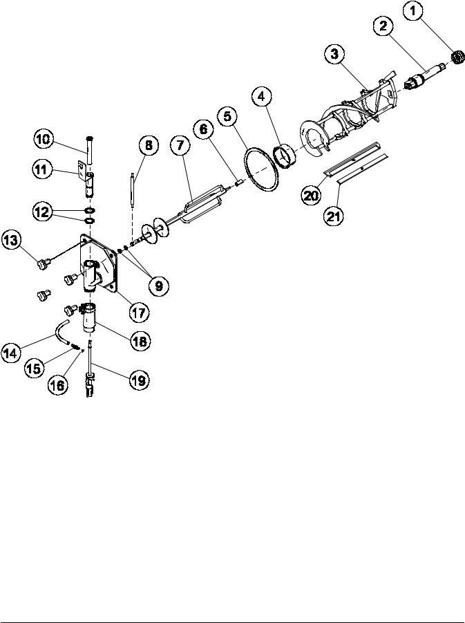
H60 Exploded View Parts Identification
ITEM |
DESCRIPTION |
PART NO. |
|
|
|
1 |
COVER--HOPPER COMPLETE |
053809 |
|
|
|
2 |
AGITATOR A. |
X44797 |
|
|
|
3 |
PANEL A.--SIDE LEFT |
X48285 |
|
|
|
4 |
STUD--NOSE CONE |
011390 |
|
|
|
5 |
PAN--DRIP 19--1/2 LONG |
035034 |
|
|
|
6 |
SHIELD--SPLASH--WIRE |
046177 |
|
|
|
7 |
TRAY--DRIP 14.8 |
046275 |
|
|
|
8 |
SCREW--1/4--20X3/8 RHM |
011694 |
|
|
|
9 |
CASTER--SWV 5/8 STEM |
018794 |
|
|
|
10 |
PANEL A.--SIDE RIGHT |
X48286 |
|
|
|
11 |
PANEL--SIDE UPPER |
042317 |
|
|
|
12 |
O--RING--.643 OD X .077W |
018572 |
|
|
|
ITEM |
DESCRIPTION |
PART NO. |
|
|
|
|
|
13 |
TUBE A.--FEED--OUTER--HT |
X34641 |
|
|
|
|
|
14 |
O--RING--.291 ID X .080W |
018550 |
|
|
|
|
|
15 |
TUBE A.--FEED--SC--INNER |
X32824-- |
5 |
|
|
|
|
16 |
GASKET--SYRUP DOOR |
045326 |
|
|
|
|
|
17 |
DOOR A.--SYRUP CABINET |
X45325 |
|
|
|
|
|
18 |
ADAPTOR A.--CASTER |
X18915 |
|
|
|
|
|
19 |
PANEL--REAR W/LOUVERS |
--026980 SP |
|
|
|
|
|
20 |
LOUVER--SIDE |
013631 |
|
|
|
|
|
21 |
PANEL A.--FRONT |
X46634 |
|
|
|
|
|
22 |
TRIM--REAR CORNER |
046668 |
|
|
|
|
|
23 |
TRIM A.--SHELF |
X45334 |
|
|
|
|
|
Model H60 |
5 |
Operator Parts Identification |
|
|
|
H60 Door and Beater Assemblies
ITEM |
DESCRIPTION |
PART NO. |
|
|
|
1 |
SEAL--DRIVE SHAFT |
032560 |
|
|
|
2 |
SHAFT--BEATER |
035527 |
|
|
|
3 |
BEATER A.--7QT--1 PIN |
X46233 |
|
|
|
4 |
BEARING--FRONT |
013116 |
|
|
|
5 |
GASKET--DOOR 5.177ID |
016672 |
|
|
|
6 |
BEARING--GUIDE |
014496 |
|
|
|
7 |
TORQUE A. |
X17381 |
|
|
|
8 |
ARM--TORQUE |
014500 |
|
|
|
9 |
O--RING--.291 ID X .080W |
018550 |
|
|
|
10 |
BEARING--SPINNER |
017032 |
|
|
|
11 |
VALVE A.--DRAW |
X54821 |
|
|
|
ITEM |
DESCRIPTION |
PART NO. |
|
|
|
12 |
O--RING--1--1/16 OD X .139W |
013029 |
|
|
|
13 |
NUT--STUD *GENERAL USAGE* |
021508 |
|
|
|
14 |
TUBE--VINYL 3/16 X 1/16 WAL |
020940-- |
|
|
|
15 |
FITTING--QD MALE INSERT |
036296 |
|
|
|
16 |
O--RING--5/16 OD X .070 W |
016272 |
|
|
|
17 |
DOOR A.--1 SPOUT--METAL |
X17373 |
|
|
|
18 |
HOUSING--SPINNER *4 SPIGOT |
017269 |
|
|
|
19 |
BLADE A.--SPINNER *8 3/8 |
X35570 |
|
|
|
20 |
BLADE--SCRAPER--PLASTIC |
046237 |
|
|
|
21 |
CLIP--SCRAPER BLADE*8.75” |
046238 |
|
|
|
Operator Parts Identification |
6 |
Model H60 |
|
|
|
H60 Syrup Tank - 045533
|
|
|
|
|
|
|
|
|
|
|
|
|
|
|
|
|
|
|
|
|
|
|
|
|
|
|
|
|
|
|
|
|
|
|
|
|
|
|
|
|
|
|
|
|
ITEM |
DESCRIPTION |
PART NO. |
||||||
|
|
|
|
|
||||
1 |
TANK--SYRUP--4 QT. |
045533 |
|
|
||||
|
|
|
|
|
||||
1a |
COVER--TANK W/ FTG |
035759- |
|
1 |
||||
|
|
|
|
|||||
1b |
TIP--NYLON--WHITE TRANSL. |
042747* |
|
|||||
|
|
|
|
|
||||
1c |
O--RING--3.437 ID X .275 W |
016037 |
|
|
||||
|
|
|
|
|
||||
1d |
TUBE--DIP--4 QT. |
015441- |
|
7 |
||||
|
|
|
|
|
||||
1d--1 |
O--RING--.291 ID X .080W |
018550 |
|
|
||||
|
|
|
|
|
||||
2 |
PLUG--Q.D. CO2 1/8 MP |
021077 |
|
|
||||
|
|
|
|
|
||||
3 |
SOCKET--Q.D. CO2 90DEG 1/4 |
021524 |
|
|
||||
|
|
|
|
|
||||
4 |
SOCKET--Q.D. LIQ.--90DEG--1/4 |
021026 |
|
|
||||
|
|
|
|
|
|
|
|
|
ITEM |
DESCRIPTION |
PART NO. |
|
|
|
4a** |
RESTRICTOR--SYRUP |
030917 |
|
|
|
4b** |
GASKET--RUBBER |
023551 |
|
|
|
5 |
O--RING--5/8 OD X .103W |
016030 |
|
|
|
6 |
PLUG--Q.D. LIQ. 3/4--18 FP |
021081 |
|
|
|
6a |
VALVE A.--QD PLUG |
021081--2 |
|
|
|
6b |
INSERT |
021081--1 |
|
|
|
7 |
DECAL--SET 4 SYRUP FLAVOR |
021523 |
|
|
|
8 |
DECAL--SYRUP TANK INST. |
045533--1 |
|
|
|
*TIP--NYLON--GREY 024261
(DUAL SUPPLIER, ORDER AS NEEDED)
**NOTE: NOT USED ON CHOCOLATE.
Model H60 |
7 |
Operator Parts Identification |
|
|
|

Accessories
ITEM |
DESCRIPTION |
PART NO. |
|
|
|
1 |
BRUSH-MIX PUMP BODY - |
023316 |
|
3” X 7” WHITE |
|
2 |
BRUSH-END-DOOR-SPOUT |
039719 |
|
|
|
3 |
KIT A.-TUNE UP |
X34615 |
|
|
|
4 |
BRUSH-DOUBLE ENDED |
013072 |
|
|
|
5 |
BRUSH-REAR BRG 1IN.D X 2IN |
013071 |
|
|
|
|
|
|
|
|
|
|
|
|
|
ITEM |
DESCRIPTION |
PART NO. |
||
|
|
|
||
6 |
BRUSH-DRAW VALVE |
014753 |
||
|
|
|
||
7 |
LUBRICANT-TAYLOR HI PERF |
048232 |
||
|
|
|
||
8 |
PAIL-MIX 10 QT. |
013163 |
||
|
|
|
||
* |
SANITIZER·KAY-5·125·PKTS |
041082 |
||
|
|
|
||
* |
SANITIZER-STERA SHEEN-GR |
055492 |
||
|
100 PKTS |
|
||
*NOT SHOWN
Operator Parts Identification |
8 |
Model H60 |
|
|
|
Section 5 |
|
|
|
|
|
|
|
|
|
Important: To the Operator |
||||||||||||||||||||||||||||||||||||||
|
|
|
|
|
|
|
|
|
|
|
|
|
|
|
|
|
|
|
|
|
|
|
|
|
|
|
|
|
|
|
|
|
|
|
|
|
|
|
|
|
|
|
|
|
|
|
|
|
|
|
|
|
|
|
|
|
|
|
|
|
|
|
|
|
|
|
|
|
|
|
|
|
|
|
|
|
|
|
|
|
|
|
|
|
|
|
|
|
|
|
|
|
|
|
|
|
|
|
|
|
|
|
|
|
|
|
|
|
|
|
|
|
|
|
|
|
|
|
|
|
|
|
|
|
|
|
|
|
|
|
|
|
|
|
|
|
|
|
|
|
|
|
|
|
|
|
|
|
|
|
|
|
|
|
|
|
|
|
|
|
|
|
|
|
|
|
|
|
|
|
|
|
|
|
|
|
|
|
|
|
|
|
|
|
|
|
|
|
|
|
|
|
|
|
|
|
|
|
|
|
|
|
|
|
|
|
|
|
|
|
|
|
|
|
|
|
|
|
|
|
|
|
|
|
|
|
|
|
|
|
|
|
|
|
|
|
|
|
|
|
|
|
|
|
|
|
|
|
|
|
|
|
|
|
|
|
|
|
|
|
|
|
|
|
|
|
|
|
|
|
|
|
|
|
|
|
|
|
|
|
|
|
|
|
|
|
|
|
|
|
|
|
|
|
|
|
|
|
|
|
|
|
|
|
|
|
|
|
|
|
|
|
|
|
|
|
|
|
|
|
|
|
|
|
|
|
|
|
|
|
|
|
|
|
|
|
|
|
|
|
|
|
|
|
|
|
|
|
|
|
|
|
|
|
|
|
|
|
|
|
|
|
|
|
|
|
|
|
|
|
|
|
|
|
|
|
|
|
|
|
|
|
|
|
|
|
|
|
|
|
|
|
|
|
|
|
|
|
|
|
|
|
|
|
|
|
|
|
|
|
|
|
|
|
|
|
|
|
|
|
|
|
|
|
|
|
|
|
|
|
|
|
|
|
|
|
|
|
|
|
|
|
|
|
|
|
|
|
|
|
|
|
|
|
|
|
|
|
|
|
|
|
|
|
|
|
|
|
|
|
|
|
|
|
|
|
|
|
|
|
|
|
|
|
|
|
|
|
|
|
|
|
|
|
|
|
|
|
|
|
|
|
|
|
|
|
|
|
|
|
|
|
|
|
|
|
|
|
|
|
|
|
|
|
|
|
|
|
|
|
|
|
|
|
|
|
|
|
|
|
|
|
|
|
|
|
|
|
|
|
|
|
|
|
|
|
|
|
|
|
|
|
|
|
|
|
|
|
|
|
|
|
|
|
|
|
|
|
|
|
|
|
|
|
|
|
|
|
|
|
|
|
|
|
|
|
|
|
|
|
|
|
|
|
|
|
|
|
|
|
|
|
|
|
|
|
|
|
|
|
|
|
|
|
|
|
|
|
|
|
|
|
|
|
|
|
|
|
|
|
|
|
|
|
|
|
|
|
|
|
|
|
|
|
|
|
|
|
|
|
|
|
|
|
|
|
|
|
|
|
|
|
|
|
|
|
|
|
|
|
|
|
|
|
|
|
|
|
|
|
|
|
|
|
|
|
|
|
|
|
|
|
|
|
|
|
|
|
|
|
|
|
|
|
|
|
|
|
|
|
|
|
|
|
|
|
|
|
|
|
|
|
|
|
|
|
|
|
|
|
|
|
|
|
|
|
|
|
|
|
|
|
|
|
|
|
|
|
|
|
|
|
|
|
|
|
|
|
|
|
|
|
|
|
|
|
|
|
|
|
|
|
|
|
|
|
|
|
|
|
|
|
|
|
|
|
|
|
|
|
|
|
|
|
|
|
|
|
|
|
|
|
|
|
|
|
|
|
|
|
|
|
|
|
|
|
|
|
|
|
|
|
|
|
|
|
|
|
|
|
|
|
|
|
|
|
|
|
|
|
|
|
|
|
|
|
|
|
|
|
|
|
|
|
|
|
|
|
|
|
|
|
|
|
|
|
|
|
|
|
|
|
|
|
|
|
|
|
|
|
|
|
|
|
|
|
|
|
|
|
|
|
|
|
|
|
|
|
|
|
|
|
|
|
|
|
|
|
|
|
|
|
|
|
|
|
|
|
|
|
|
|
|
|
|
|
|
|
|
|
|
|
|
|
|
|
|
|
|
|
|
|
|
|
|
|
|
|
|
|
|
|
|
|
|
|
|
|
|
|
|
|
|
|
|
|
|
|
|
|
|
|
|
|
|
|
|
|
|
|
|
|
|
|
|
|
|
|
|
|
|
|
|
|
|
|
|
|
|
|
|
|
|
|
|
|
|
|
|
|
|
|
|
|
|
|
|
|
|
|
|
|
|
|
|
|
|
|
|
|
|
|
|
|
|
|
|
|
|
|
|
|
|
|
|
|
|
|
|
|
|
|
|
|
|
|
|
|
|
|
|
|
|
|
|
|
|
|
|
|
|
|
|
|
|
|
|
|
|
|
|
|
|
|
|
|
|
|
|
|
|
|
|
|
|
|
|
|
|
|
|
|
|
|
|
|
|
|
|
|
|
|
|
|
|
|
|
|
|
|
|
|
|
|
|
|
|
|
|
|
|
|
|
|
|
|
|
|
|
|
|
|
|
|
|
|
|
|
|
|
|
|
|
|
|
|
|
|
|
|
|
|
|
|
|
|
|
|
|
|
|
|
|
|
|
|
|
|
|
|
|
|
|
|
|
|
|
|
|
|
|
|
|
|
|
|
|
|
|
|
|
|
|
|
|
|
|
|
|
|
|
|
|
|
|
|
|
|
|
|
|
|
|
|
|
|
|
|
|
|
|
|
|
|
|
|
|
|
|
|
|
|
|
|
|
|
|
|
|
|
|
|
|
|
|
|
|
|
|
|
|
|
|
|
|
|
|
|
|
|
|
|
|
|
|
|
|
|
|
|
|
|
|
|
|
|
|
|
|
|
|
|
|
|
|
|
|
|
|
|
|
|
|
|
|
|
|
|
|
|
|
|
|
|
|
|
|
|
|
|
|
|
|
|
|
|
|
|
|
|
|
|
|
|
|
|
|
|
|
|
|
|
|
|
|
|
|
|
|
|
|
|
|
|
|
|
|
|
|
|
|
|
|
|
|
|
|
|
|
|
|
|
|
|
|
|
|
|
|
|
|
|
|
|
|
|
|
|
|
|
|
|
|
|
|
|
|
|
|
|
|
|
|
|
|
|
|
|
|
|
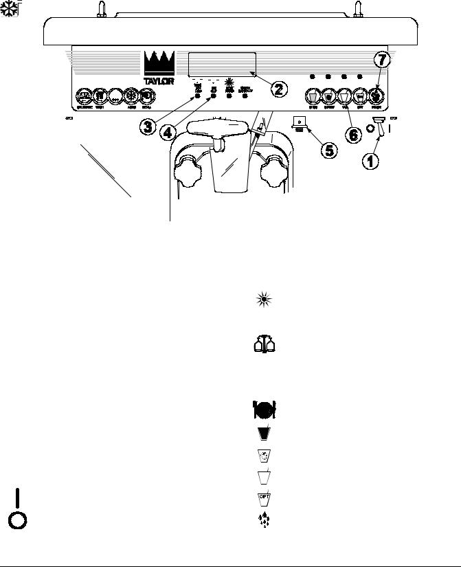
Item |
Description |
|
|
|
|
|
|
1 |
Power Switch (Toggle) |
|
|
2 |
Liquid Crystal Display |
|
|
|
|
|
|
3 |
LCD Indicator -- MIX LOW (PCB A.--LED) |
|
|
|
|
|
|
4 |
LCD Indicator -- MIX OUT (PCB A.--LED) |
|
|
|
|
||
|
|
|
|
5 |
Consistency Control (Switch--Torque) |
|
|
|
|
||
|
|
|
|
6 |
Flavor Selector Keypad (Switch--Membrane) |
|
|
|
|
|
|
7 |
Rinse Key (Switch--Membrane) |
|
|
|
|
|
|
Symbol Definitions
To better communicate in the International arena, the words on many of our operator switches and buttons have symbols to indicate their functions. Your Taylor equipment is designed with these International symbols.
The following chart identifies the symbol definitions used on the operator switches.
= ON
= OFF
=MIX LOW
=MIX OUT
=HEAT MODE
=CLEAN MANUALLY
=CALIBRATE
=WASH
=AUTO
=MENU
=CHOCOLATE
=STRAWBERRY
=VANILLA
=OPTIONAL
=RINSE
Model H60 |
9 |
Important: To the Operator |
|
|
|

Power Switch
When placed in the ON position, the power switch allows control panel operation. The power switch is located on the left side of the control channel.
Liquid Crystal Display
The Liquid Crystal Display (LCD) is located on the front control panel. The LCD is used to show the current mode of operation, and whether or not there is sufficient mix.
LCD Indicator - MIX LOW
The “MIX LOW” indicator flashes to indicate that there is a low supply of mix. The mix hopper should be filled as soon as possible.
LCD Indicator - MIX OUT
The MIX OUT light will illuminate, indicating that the mix hopper has an insufficient supply of mix to operate the freezer. The MIX OUT indicator will flash. At this time, the freezer will go into the STANDBY mode of operation. To return the freezer to the AUTO mode, fill the hopper with mix and press the AUTO key. The freezer will automatically begin operation.
Consistency Control
The viscosity (thickness) of the shake is controlled by a sensing device called the consistency control. The consistency control knob is located to the lower right of the control channel. To achieve a thicker shake, turn the knob clockwise and counterclockwise to achieve a thinner shake consistency.
Allow the refrigeration system to cycle on and off 2 or 3 times before an accurate consistency can be evaluated.
Flavor Selector Keypad
Four shake flavors are offered from the Model H60 freezer: chocolate, strawberry, vanilla (unflavored product), and an optional flavor. Press the desired shake flavor key and open the draw valve. Product and syrup will automatically blend to produce the chosen flavor.
RINSE
After the shake is drawn, press the RINSE key to rinse excess syrup and mix from the spinner housing.
Reset Mechanism
The reset button is located under the right side panel. The reset mechanism protects the beater motor from an overload condition. If an overload occurs, the reset mechanism will trip. To properly reset the freezer, press the reset button firmly and clear the tone per instructions in “Clearing Fault Tones” on page 14.
If the reset mechanism trips again, contact your authorized Taylor Distributor to resolve the problem.
 Warning: Do not use metal objects to press the reset button. Failure to comply may result in severe personal injury or death.
Important: To the Operator |
10 |
Model H60 |
|
|
|

Operating Screen Descriptions
When the machine is powered the system will initialize. The screen will display “INITIALIZING”. There will be four types of data the system will check: LANGUAGE, SYSTEM DATA, CONFIG DATA, and LOCKOUT DATA. During the INITIALIZING... LANGUAGE screen, the alarm will be on. If the system data, configuration data, or lockout history data has become corrupt, the following screen will alert the operator that the system settings may have been changed.
NVRAM FAULT
RESET TO DEFAULTS
PRESS SEL KEY
Once the system has initialized the SAFETY TIMEOUT screen is displayed and the alarm is turned on.
SAFETY TIMEOUT
ANY KEY ABORTS
This screen will be displayed, with the alarm on, for 60 seconds or until any key is pressed.
After the safety timeout has been completed, and the power switch is OFF, one of the following screens is displayed.
The first screen is displayed if the machine is not in a brush clean state.
POWER SWITCH OFF
MIX: OUT TIME: 4:30
HOPPER: 62.1
BARREL: 67.7
If any of the requirements for a brush clean have not been met, the time displayed will remain at 5:00 minutes. When all the requirements for a brush cleaning are met, and the five minutes expire, the screen will change to the second screen, which is the standard power switch OFF screen.
POWER SWITCH OFF
-= - = - = - = - = - UNIT CLEANED
When the power switch is set in the ON position, the system mode of operation screen is displayed. In this example, the machine is ON, but no mode of operation has been selected. The second line of the display indicates whether there is a sufficient supply of mix in the hopper or if there is a LOW or OUT mix condition. The third line of the display shows the temperature of the mix hopper. After pressing the AUTO key, the last line of the display shows the month and date (MM = month, DD = day) that the machine needs to be disassembled and brush cleaned.
MODE: OFF
MIX: OK
HOPPER: 40.0F
BRUSH CLEAN ON: MM/DD
The next display indicates the freezer is operating in two different modes. The following information is given:
The machine is operating in the WASH and PUMP modes and the mix level in the hopper is low. The temperature of the mix hopper is 40_F (4.4_C), and the machine needs to be brush cleaned on October 31st.
MODE: WSH-PMP
MIX: LOW
HOPPER TEMP: 40.0 F
BRUSH CLEAN ON: 10/31
Model H60 |
11 |
Important: To the Operator |
|
|
|

The following displays pertain to the HEAT cycle:
Effective 12/8/06, a System Alert screen was added to display an alert and alarm 15 minutes prior to the start of the heat cycle. The system alert functions similar to the Fault Description except there is no menu item. The alarm will sound and show on the display. The alarm will sound until the SEL key is pressed to clear the fault. This feature allows the operator time to make sure the freezer is in AUTO or STANDBY, and has the proper amount of mix in the hopper before the start of the heat cycle.
SYSTEM ALERT
HEAT TREAT CYCLE
SEL
While in the heating phase, you will see this display. It shows the present temperature of the hopper.
MODE: HEAT
PHASE: HEAT
HOPPER: 140.0 F
BRUSH CLEAN ON: MM/DD
The mix temperature must be raised above 151_F (66.1_C) within 90 minutes or the freezer will be locked in STANDBY, and the cycle failure display will appear.
In the example, the hopper temperature is 140_F (60_C). The phase shows that the machine is in the heat phase of the heat treatment cycle.
When the heating phase is complete, the freezer goes into the holding phase of the cycle. The holding phase will hold the temperature above 151_F (66.1_C) for a minimum of 30 minutes.
In this example, the hopper temperature is 151_F (66.1_C).
MODE: HEAT
PHASE: HOLD
HOPPER: 151.0 F
BRUSH CLEAN ON: MM/DD
The final phase of the heat treatment cycle is the cooling phase. Now the freezer must cool the mix below 41_F (5_C). If the product fails to cool in two hours, the freezer will lock out.
070316
This example illustrates that the temperature is being lowered, but has not yet reached the set point.
MODE: HEAT
PHASE: COOL
HOPPER TEMP: 55.0 F
BRUSH CLEAN ON: MM/DD
The entire heat treatment cycle must be completed in four hours.
When the entire heat cycle has been completed, the normal display will appear, showing the machine in the STANDBY mode. The machine may now be placed in the AUTO mode or left in the STANDBY mode.
MODE: STANDBY
MIX: OK
HOPPER: 41.0 F
BRUSH CLEAN ON: MM/DD
Hard Lock: There are two causes for a hard lock:
1.Fourteen days have elapsed since the last brush cleaning. The following screen will be displayed.
14 DAY TIMEOUT CLEANING REQ’D FREEZER LOCKED PRESS SEL KEY
2.There has been a thermistor failure (freezing cylinder, hopper, or glycol) during the heat treatment process.
SYSTEM FAULT
SERVICE REQ’D
FREEZER LOCKED
PRESS SEL KEY
All four LED’s on the front of the freezer will light. Press the MENU/SEL key.
The next display is the screen which will appear after the failure message. To comply with health codes, heat treatment system freezers must complete a heat treatment cycle daily, and must also be brush cleaned every 14 days. Brush cleaning is the normal disassembly and cleaning procedures. Failure to
Important: To the Operator |
12 |
Model H60 |
|
|
|

follow these guidelines will cause the control to lock the freezer out of the AUTO mode. Press the WASH key.
NO AUTO OPERATION
ALLOWED UNTIL
BRUSH CLEANING
PRESS WASH KEY
The next display is the screen which will appear after the brush cleaning message and illustrates that the control is in the OFF mode and the machine needs to be disassembled and brush cleaned.
MODE: OFF
MIX: OK
HOPPER TEMP: 41.0 F
FREEZER LOCKED
Once the unit is unlocked, only the MIX OUT and MIX LOW LED’s will light.
Soft Lock: If a heat treatment cycle has not been initiated within the last 24 hours, all four LED’s on the front of the machine will light and a message will appear on the LCD. Line 3 of the LCD will indicate the reason the message appears.
NO HEAT TREAT START
BECAUSE
VARIABLE MESSAGE
PRESS SEL KEY
Following are the variable messages which will appear on line 3:
1.POWER SWITCH OFF: Power switch was in the OFF position.
2.MIX OUT PRESENT: There was mix out condition present.
3.AUTO OR STANDBY OFF: The unit was not in the AUTO or STANDBY mode.
4.NO HEAT CYCLE TRIED: A heat treatment cycle was not attempted in the last 24 hours. (AUTO HEAT TIME was advanced, or a power loss was experienced at the time the cycle was to occur, or a heat cycle failure not due to a thermistor failure.)
If the following screen appears, a soft lock has occurred during the heat treatment cycle.
HEAT TREAT CYCLE
FAILURE
FREEZER LOCKED
PRESS SEL KEY
If the temperature of the product has not fallen below 41_F (5_C) by the end of the COOL cycle, the following screen will appear.
PRODUCT OVER TEMP
FREEZER LOCKED
PRESS SEL KEY
Press the MENU/SEL key to advance to the next display.
When one of these messages appears, automatic freezer operation cannot take place until the freezer is disassembled and brush cleaned or has completed a heat treatment cycle.
The next display will instruct the operator to start a heat treatment cycle manually (by pressing the AUTO key), or to disassemble and brush clean the freezer. If the AUTO key is pressed, the freezer will automatically start the heat treatment cycle and only the heat cycle LED will light.
NO AUTO OPERATION
ALLOWED. PRESS
AUTO FOR HEAT CYCLE
WASH TO BRUSH CLEAN
If the WASH key is pressed, the next display will appear and the freezer will have to be disassembled and brush cleaned.
MODE: OFF
MIX: OK
HOPPER TEMP: 41.0F
FREEZER LOCKED
Once the freezer is unlocked by starting a heat treatment cycle, only the heat cycle LED will light. If the freezer is unlocked by brush cleaning, the mix low and mix out LED’s will light.
Model H60 |
13 |
Important: To the Operator |
|
|
|

Operator Menu
The OPERATOR MENU is used to enter the operator function displays. To access the OPERATOR MENU, simply press the MENU/SEL key. The cursor will flash over the letter “A” indicating that this is screen “A”. To select a different screen, use the arrow keys and move the cursor to the desired screen selection and press the MENU/SEL key.
OPERATOR MENU |
|
A B C D E F G H I J K |
|
EXIT FROM MENU |
|
<- - - - - -> |
SEL |
Screen “B” is FAULT DESCRIPTION. The fault description will indicate if there is a fault with the freezer and the side of the freezer where the fault occurred.
FAULT DESCRIPTION
VARIABLE MESSAGE
CLR |
SEL |
Clearing Fault Tones
To clear the tone for any faults which have been corrected, press the CALIBRATE key. To see if there is more than one fault per cylinder, press the MENU/SEL key. When the last fault is displayed, the control will return to the OPERATOR MENU. To return to the main screen, move the cursor to “A” and press the MENU/SEL key again.
Listed below are the variable messages which will appear, along with the corrective action:
1.NO FAULT FOUND: There was no fault found in the freezer. Nothing will appear on the screen after this variable message appears.
2.BEATER OVERLOAD: Press the reset button firmly. Clear the tone per instructions in “Clearing Fault Tones” on page 14.
060807
3.CHK REFRIG SYS PSI: Place the power switch in the OFF position. Wait 5 minutes for the machine to cool. Place the power switch in the ON position. Clear the tone per instructions in “Clearing Fault Tones” on page 14.
4.COMP ON TOO LONG: Place the power switch in the OFF position. Call service technician. Clear the tone per instructions in “Clearing Fault Tones” on page 14.
5.HOPPER THERM BAD: Place the power switch in the OFF position. Call service technician.
6.BARREL THERM BAD: Place the power switch in the OFF position. Call service technician.
7.GLYCOL THERM BAD: Place the power switch in the OFF position. Call service technician.
8.HOPPER OVER TEMP: The hopper temperature has risen too high as follows. Clear the tone per instructions in “Clearing Fault Tones” on page 14.
a.The hopper temperature reaches 41_F. (5_C.) or higher after a power failure.
b.The hopper temperature has not fallen below 41_F. (5_C.) by the end of the COOL phase in the heat cycle.
9.BARREL OVER TEMP: The barrel temperature has risen too high as follows. Clear the tone per instructions in “Clearing Fault Tones” on
page 14.
a.The barrel temperature reaches 41_F. (5_C.) or higher after a power failure.
b.The barrel temperature has not fallen below 41_F. (5_C.) by the end of the COOL phase in the heat cycle.
10.POWER FAILURE: This message will appear in the FAULT DESCRIPTION if a power failure has occurred. Clear the tone per instructions in “Clearing Fault Tones” on page 14.
Important: To the Operator |
14 |
Model H60 |
|
|
|
 Loading...