


 Loading...
GSX-R600
9 9 5 0 0 - 3 5 1 0 0 - 0 1 E

FOREWORD |
|
|
GROUP INDEX |
|
|
This manual contains an introductory description on |
|
|
|||
the SUZUKI GSX-R600 and procedures for its |
|
|
|||
|
1 |
||||
inspection/service and overhaul of its main compo- |
GENERAL INFORMATION |
||||
nents. |
|
|
|||
Other information considered as generally known is |
|
|
|||
|
|
||||
not included. |
|
|
PERIODIC MAINTENANCE |
2 |
|
Read the GENERAL INFORMATION section to |
|||||
familiarize yourself with the motorcycle and its main- |
|
|
|||
tenance. Use this section as well as other sections |
|
|
|||
|
3 |
||||
to use as a guide for proper inspection and service. |
ENGINE |
||||
This manual will help you know the motorcycle bet- |
|||||
|
|
||||
ter so that you can assure your customers of fast |
|
|
|||
|
|
||||
and reliable service. |
|
|
FI SYSTEM DIAGNOSIS |
4 |
|
|
|
|
|||
* This manual has been prepared on the basis |
|
|
|||
|
|
|
|
||
of the latest specifications at the time of publi- |
|
|
|
|
|
|
|
|
|
||
|
|
FUEL SYSTEM AND THROTTLE |
5 |
||
cation. If modifications have been made since |
|
|
|||
then, differences may exist between the con- |
|
|
BODY |
||
|
|
6 |
|||
tent of this manual and the actual motorcycle. |
|
|
E |
||
|
|
|
|
||
* Illustrations in this manual are used to show |
|
|
L |
|
|
|
|
|
|
||
the basic principles of operation and work |
|
|
EXHAUST SYSTEM |
|
|
procedures. They may not represent the |
|
|
|
|
|
actual motorcycle exactly in detail. |
|
P |
|
||
|
|
COOLING AND LUBRICATION |
7 |
||
* This manual is written for persons who have |
|
|
|||
M |
|
SYSTEM |
|||
enough knowledge, skills and tools, including |
|
|
|
||
special tools, for servicing SUZUKI motorcy- |
|
|
|
|
|
|
|
|
|
||
cles. If you do not have the proper knowledge |
|
|
|
|
|
S |
|
|
|
8 |
|
and tools, ask your authorizedASUZUKI |
|
|
CHASSIS |
||
motorcycle dealer to help you. |
|
|
|
|
|
|
|
|
|
|
|
|
|
|
ELECTRICAL SYSTEM |
9 |
|
Inexperienced mechanics or mechanics |
|
|
|
|
|
without the proper tools and equipment |
|
|
|
|
|
|
|
|
10 |
||
may not be able to properly perform the |
|
|
SERVICING INFORMATION |
||
services described in this manual. |
|
|
|||
|
|
|
|
||
Improper repair may result in injury to the |
|
|
|
|
|
|
|
|
|
||
mechanic and may render the motorcycle |
|
|
EMISSION CONTROL |
11 |
|
unsafe for the rider and passenger. |
|
|
INFORMATION |
||
|
|
|
|
||
|
|
|
|
|
|
|
|
|
|
|
|
|
|
|
WIRING DIAGRAM |
12 |
|
|
|
|
|
|
|
© COPYRIGHT SUZUKI MOTOR CORPORATION 2006

HOW TO USE THIS MANUAL
TO LOCATE WHAT YOU ARE LOOKING FOR:
1.The text of this manual is divided into sections.
2.The section titles are listed in the GROUP INDEX.
3.Holding the manual as shown at the right will allow you to find the first page of the section easily.
4.The contents are listed on the first page of each section to help you find the item and page you need.
COMPONENT PARTS AND WORK TO BE DONE
Under the name of each system or unit, is its exploded view. Work instructions and other service information such as the tightening torque, lubricating points and locking agent points, are provided.
Example: Front wheel
1 |
Brake disc |
|
E |
||
2 |
Collar |
|
|||
3 |
Dust seal |
|
|||
4 |
Bearing |
|
|||
5 |
Spacer |
|
L |
||
6 |
Front axle |
|
|||
|
P |
||||
7 |
Front wheel |
|
|||
A Front axle bolt |
M |
||||
B |
Brake disc bolt |
||||
A |
|||||
|
|
|
|
||
ITEM N·m kgf-m lb-ftS |
|||||
A |
100 |
10.0 |
72.5 |
||
B |
23 |
2.3 |
16.5 |
||
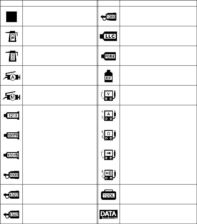
SYMBOL
Listed in the table below are the symbols indicating instructions and other information necessary for servicing. The meaning of each symbol is also included in the table.
SYMBOL |
DEFINITION |
SYMBOL |
DEFINITION |
Torque control required.
Data beside it indicates specified
Apply THREAD LOCK SUPER “1360”.
torque.
99000-32130
Apply oil. Use engine oil unless other- |
Use engine coolant. |
wise specified. |
99000-99032-11X (Except USA) |
Apply molybdenum oil solution. (Mixture of engine oil and SUZUKI
Use fork oil.
MOLY PASTE in a ratio of 1:1)
99000-99001-SS5
Apply SUZUKI SUPER GREASE “A” |
|
|
|||
or equivalent grease. |
|
|
Apply or use brake fluid. |
||
99000-25010 |
|
|
|
E |
|
|
|
|
|
|
|
Apply SUZUKI MOLY PASTE. |
|
L |
|||
99000-25140 |
|
|
|
Measure in voltage range. |
|
|
|
P |
|||
|
|
|
|
||
|
|
|
M |
|
|
Apply SUZUKI BOND “1215” |
|
|
|||
or equivalent bond. |
|
|
Measure in current range. |
||
99000-31110 |
|
|
|
|
|
|
|
|
|
|
|
Apply |
SUZUKI |
|
|
|
|
|
BONDA“1207B”. |
|
Measure in resistance range. |
||
99104-31140 (U A) |
|
|
|||
|
|
|
|||
|
|
|
|||
Apply SUZUKI BOND “1207B”. |
|
Measure in diode test range. |
|||
99000-31140 (Except USA) |
|
||||
|
|
||||
|
|
||||
Apply THREAD LOCK SUPER “1303”. |
Measure in continuity test range. |
||||
99000-32030 |
|
|
|
||
|
|
|
|
||
Apply THREAD LOCK SUPER “1322”
or equivalent thread lock. Use special tool. 99000-32110
Apply THREAD LOCK “1342”.
Indication of service data.
99000-32050
ABBREVIATIONS USED IN THIS MANUAL
A
ABDC AC ACL API ATDC
ATM Pressure
A/F
B
BBDC
BTDC
B+
C
CKP Sensor
CKT
CLP Switch
CMP Sensor
CO
CPU
E
: After Bottom Dead Center |
ECM |
|
: Engine Control Module |
||
: Alternating Current |
|
|
Engine Control Unit (ECU) |
||
: Air Cleaner, Air Cleaner Box |
|
|
(FI Control Unit) |
||
: American Petroleum Institute |
ECT Sensor |
: Engine Coolant Temperature |
|||
: After Top Dead Center |
|
|
Sensor (ECTS), Water Temp. |
||
: Atmospheric Pressure |
|
|
Sensor (WTS) |
||
: Atmospheric Pressure sensor |
EVAP |
|
: Evaporative Emission |
||
(APS, AP Sensor) |
|
EVAP Canister : Evaporative Emission |
|||
: Air Fuel Mixture |
|
|
|
Canister (Canister) |
|
|
|
|
EXC System |
: Exhaust Control System (EXCS) |
|
|
|
|
EXC Valve |
: Exhaust Control Valve (EXCV) |
|
: Before Bottom Dead Center |
EXCV Actuator |
: Exhaust Control Valve Actuator |
|||
: Before Top Dead Center |
|
|
(EXCVA) |
||
: Battery Positive Voltage |
F |
|
E |
||
|
|
||||
|
|
|
L |
||
|
|
|
FI |
||
|
|
|
|
: Fuel Injection, Fuel Injector |
|
: Crankshaft Position Sensor |
FP |
: Fuel Pump |
|||
|
|
||||
(CKPS) |
|
|
F R |
|
: Fuel Pressure Regulator |
: Circuit |
|
|
FP Relay |
: Fuel Pump Relay |
|
|
|
M |
|
|
|
: Clutch Lever Position Switch |
G |
|
|
||
(Clutch Switch) |
|
|
|
||
: Camshaft Position Sensor |
GEN |
|
: Generator |
||
|
S |
|
|
|
|
(CMPS) |
|
A GND |
|
: Ground |
|
: Carbon Monoxide |
|
GP Switch |
: Gear Position Switch |
||
: Central Processing Unit
H
D |
|
HC |
: Hydrocarbons |
DC |
: Direct Current |
|
|
DMC |
: Dealer Mode Coupler |
I |
|
DOHC |
: Double Over Head Camshaft |
IAP Sensor |
: Intake Air Pressure Sensor (IAPS) |
DRL |
: Daytime Running Light |
|
(MAP Sensor) |
DTC |
: Diagnostic Trouble Code |
IAT Sensor |
: Intake Air Temperature Sensor |
|
|
|
(IATS) |
|
|
IG |
: Ignition |
|
|
L |
|
|
|
LCD |
: Liquid Crystal Display |
|
|
LED |
: Light Emitting Diode |
|
|
|
(Malfunction Indicator Lamp) |
|
|
LH |
: Left Hand |
M
MAL-Code |
: Malfunction Code |
|
(Diagnostic Code) |
Max |
: Maximum |
MIL |
: Malfunction Indicator Lamp |
|
(LED) |
Min |
: Minimum |
N
NOX : Nitrogen Oxides
O
OHC |
: Over Head Camshaft |
OPS |
: Oil Pressure Switch |
P
PCV |
: Positive Crankcase |
|
|
|||
|
Ventilation (Crankcase Breather) |
E |
||||
R |
|
|
|
|
||
|
|
|
P |
|||
RH |
: Right Hand |
|||||
ROM |
: Read Only Memory |
|||||
M |
L |
|||||
S |
|
|
|
|
||
|
|
Automotive |
|
|||
SAE |
: Society of |
|
||||
|
Engineers |
|
||||
SDS |
: Suzuki Diagnosis System |
|
||||
STP Sensor |
: SecondarySecondaryThrottle Position Sensor |
|
||||
STC System |
: |
|
Throttle Control System |
|
||
|
(STC |
) |
|
|
|
|
|
(STPS) |
|
|
|
||
ST Valve |
: Secondary Throttle Valve (STV) |
|
||||
STV Actuator |
: Secondary Throttle Valve Actuator |
|
||||
|
(STVA) |
|
|
|
||
T |
|
|
|
|
|
|
TO Sensor |
: Tip-Over Sensor (TOS) |
|
||||
TP Sensor |
: Throttle Position Sensor (TPS) |
|
||||
WIRE COLOR
B |
: Black |
G |
: Green |
P |
:Pink |
Bl |
: Blue |
Gr |
: Gray |
R |
: Red |
Br |
: Brown |
Lbl |
: Light blue |
W |
: White |
Dg |
: Dark green |
Lg |
: Light green |
Y |
: Yellow |
Dgr |
: Dark gray |
O |
: Orange |
|
|
B/Bl |
: Black with Blue tracer |
|
B/Br |
: Black with Brown tracer |
B/G |
: Black with Green tracer |
|
B/Lg |
: Black with Light green tracer |
B/R |
: Black with Red tracer |
|
B/W |
: Black with White tracer |
B/Y |
: Black with Yellow tracer |
|
Bl/B |
: Blue with Black tracer |
Bl/G |
: Blue with Green tracer |
|
Bl/R |
: Blue with Red tracer |
Bl/W |
: Blue with White tracer |
|
Bl/Y |
: Blue with Yellow tracer |
Br/Y |
: Brown with Yellow tracer |
|
G/B |
: Green with Black tracer |
G/Bl |
: Green with Blue tracer |
|
G/R |
: Green with Red tracer |
G/W |
: Green with White tracer |
|
G/Y |
: Green with Yellow tracer |
Gr/B |
: Gray with Black tracer |
|
Gr/R |
: Gray with Red tracer |
Gr/W |
: Gray with White tracer |
|
Gr/Y |
: Gray with Yellow tracer |
Lg/BI |
: Light green with Blue tracer |
Lg/G |
: Light green with Green tracer |
|
|
|
|
|
L |
Lg/W |
: Light green with White tracer |
O/B |
: OrangeEwith Black tracer |
|
O/BI |
: Orange with Blue tracer |
|
P |
|
|
O/G |
: Orange with Green tracer |
||
O/R |
: Orange with Red tracer |
|
O/W |
: Orange with White tracer |
O/Y |
: Orange with Yellow tracer |
M |
: ink with Black tracer |
|
/B |
||||
P/W |
: Pink with White tracer |
|
R/B |
: Red with Black tracer |
R/Bl |
: Red with Blue tracer |
|
R/Y |
: Red with Yellow tracer |
R/W |
: Red with White tracer |
|
W/B |
: White with Black tracer |
W/Bl |
S |
|
: White with Green tracer |
|
: White with Blue tracer |
A W/G |
|||
W/R |
: White with Red tracer |
|
W/Y |
: White with Yellow tracer |
Y/B |
: Yellow with Black tracer |
|
Y/Bl |
: Yellow with Blue tracer |
Y/G |
: Yellow with Green tracer |
|
Y/R |
: Yellow with Red tracer |
Y/W |
: Yellow with White tracer |
|
|
|
GENERAL INFORMATION 1-1
GENERAL INFORMATION
1
CONTENTS
WARNING/CAUTION/NOTE......................................................................... |
|
|
|
1- 2 |
|
GENERAL PRECAUTIONS .......................................................................... |
|
|
|
1- 2 |
|
SUZUKI GSX-R600K6 (’06-MODEL)............................................................ |
|
|
1- 4 |
||
SERIAL NUMBER LOCATION ..................................................................... |
|
|
1- 4 |
||
FUEL, OIL AND ENGINE COOLANT RECOMMENDATION....................... |
1- 5 |
||||
FUEL (FOR USA AND CANADA).......................................................... |
|
|
1- 5 |
||
FUEL (FOR OTHER COUNTRIES) ........................................................ |
|
|
1- 5 |
||
ENGINE OIL (FOR USA)........................................................................ |
|
|
|
1- 5 |
|
ENGINE OIL (FOR OTHER COUNTRIES) |
............................................. |
1- 5 |
|||
BRAKE FLUID |
........................................................................................ |
|
|
|
1- 5 |
FRONT FORK ..................................................................................OIL |
|
|
|
1- 6 |
|
ENGINE COOLANT................................................................................ |
|
|
E |
1- 6 |
|
WATER FOR MIXING |
|
|
1- 6 |
||
|
|
L |
|||
ANTI-FREEZE/ENGINE COOLANT |
|
1- 6 |
|||
|
|
||||
LIQUID AMOUNT .............................OF WATER/ENGINE COO ANT |
1- 6 |
||||
BREAK-IN PROCEDURES |
|
P |
1- 7 |
||
|
|
|
|||
CYLINDER IDENTIFICATION....................................................................... |
M |
|
1- 7 |
||
INFORMATION LABELS |
|
1- 8 |
|||
|
|
|
|||
SPECIFICATIONS |
A |
|
|
1- 9 |
|
|
|
|
|
||
DIMENSIONS AND .............................................................DRY M SS |
|
|
1- 9 |
||
ENGINE |
S |
|
|
|
1- 9 |
|
|
|
|
||
DRIVE TRAIN ......................................................................................... |
|
|
|
|
1- 9 |
CHASSIS ................................................................................................ |
|
|
|
|
1-10 |
ELECTRICAL ......................................................................................... |
|
|
|
|
1-10 |
CAPACITIES .......................................................................................... |
|
|
|
|
1-10 |
COUNTRY AND AREA CODES
The following codes stand for the applicable country(-ies) and area(-s).
CODE |
COUNTRY or AREA |
EFFECTIVE FRAME NO. |
|
|
|
E-02 |
U.K. |
JS1CE111100100001 – |
E-19 (GSX-R600) |
E.U. |
JS1CE111100100001 – |
E-19 (GSX-R600U2) |
E.U. |
JS1CE211100100001 – |
E-19 (GSX-R600U3) |
E.U. |
JS1CE311100100001 – |
E-24 |
Australia |
JS1CE121300100001 – |
E-03 |
U.S.A. (Except for California) |
JS1GN7DA 62100001 – |
E-28 |
Canada |
JS1GN7DA 62100001 – |
E-33 |
California (U.S.A.) |
JS1GN7DA 62100001 – |

1-2 GENERAL INFORMATION
WARNING/CAUTION/NOTE
Please read this manual and follow its instructions carefully. To emphasize special information, the symbol and the words WARNING, CAUTION and NOTE have special meanings. Pay special attention to the messages highlighted by these signal words.
Indicates a potential hazard that could result in death or injury.
Indicates a potential hazard that could result in motorcycle damage.
NOTE:
Indicates special information to make maintenance easier or instructions clearer.
Please note, however, that the warnings and cautions contained in this manual cannot possibly cover all potential hazards relating to the servicing, or lack of servicing, of the motorcycle. In addition to the WARNINGS and CAUTIONS stated, you must use good judgement and basic mechanical safety principles. If you
are unsure about how to perform a particular service operation, ask a more experienced mechanic for advice.
|
E |
|
GENERAL PRECAUTIONS |
L |
|
P |
||
|
*Proper service and repair procedures areMimportant for the safety of the service mechanic and the safety and reliability of theAmotorcycle.
*When 2 or more personsSwork together, pay attention to the safety of each other.
*When it is necessary to run the engine indoors, make sure that exhaust gas is forced outdoors.
*When working with toxic or flammable materials, make sure that the area you work in is wellventilated and that you follow all of the material manufacturer’s instructions.
*Never use gasoline as a cleaning solvent.
*To avoid getting burned, do not touch the engine, engine oil, radiator and exhaust system until they have cooled.
After servicing the fuel, oil, water, exhaust or brake systems, check all lines and fittings related to the system for leaks.

GENERAL INFORMATION 1-3
*If parts replacement is necessary, replace the parts with Suzuki Genuine Parts or their equivalent.
*When removing parts that are to be reused, keep them arranged in an orderly manner so that they may be reinstalled in the proper order and orientation.
*Be sure to use special tools when instructed.
*Make sure that all parts used in reassembly are clean. Lubricate them when specified.
*Use the specified lubricant, bond, or sealant.
*When removing the battery, disconnect the negative cable first and then the positive cable.
*When reconnecting the battery, connect the positive cable first and then the negative cable, and replace the terminal cover on the positive terminal.
*When performing service to electrical parts, if the service procedures do not require use of battery power, disconnect the negative cable from the battery.
*When tightening the cylinder head or case bolts and nuts, tighten the larger sizes first. Always tighten the bolts and nuts diagonally from the inside toward outside and to the specified tightening torque.
*Whenever you remove oil seals, gaskets, packing, O-rings, locking washers, self-locking
nuts, cotter pins, circlips and certain other parts as specified, be sure to replace them with new ones. Also, before installing these new parts, be sureEto remove any left over material from the mating surfaces. L
*Never reuse a circlip. When installing a new circlip, take care not to expand the end gap larger than required to slip the circlip over the shaft.PAfter installing a circlip, always ensure that it is completely seated in its groove and securely fitted.
*Use a torque wrench to tighten fastenersMto the specified torque. Wipe off grease and oil if a thread is smeared with them.
*After reassembling, checkAparts for tightness and proper operation.
*To protect the environment,Sdo not unlawfully dispose of used motor oil, engine coolant and other fluids: batteries and tires.
*To protect Earth’s natural resources, properly dispose of used motorcycle and parts.
1-4 GENERAL INFORMATION
SUZUKI GSX-R600K6 (’06-MODEL)
RIGHT SIDE
|
E |
|
L |
|
P |
|
M |
A |
|
S |
LEFT SIDE |
|
|
• Difference between illustrations and actual motorcycle may exist depending on the markets.
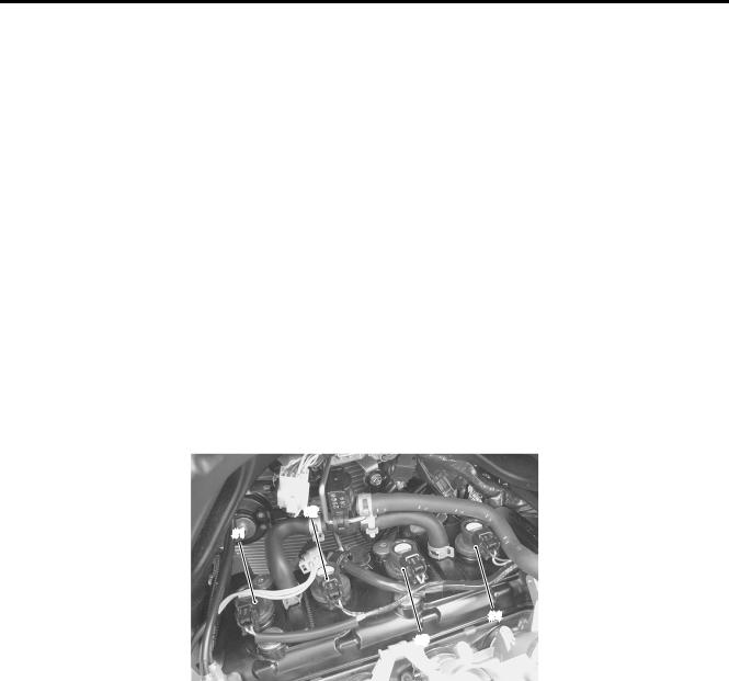
SERIAL NUMBER LOCATION
The frame serial number or V.I.N. (Vehicle Identification Number) 1 is stamped on the right side of the steering head pipe. The engine serial number 2 is located on the right side of the crankcase. These numbers are required especially for registering the machine and ordering spare parts.
GENERAL INFORMATION 1-5
FUEL, OIL AND ENGINE COOLANT RECOMMENDATION
FUEL (FOR USA AND CANADA)
Use only unleaded gasoline of at least 87 pump octane (R/2 + M/2) or 91 octane or higher rated by the research method.
Gasoline containing MTBE (Methyl Tertiary Butyl Ether), less than 10% ethanol, or less than 5% methanol with appropriate cosolvents and corrosion inhibitor is permissible.
FUEL (FOR OTHER COUNTRIES)
Gasoline used should be graded 91 octane (Research Method) or higher. Unleaded gasoline is recommended.
ENGINE OIL (FOR USA)
Oil quality is a major contributor to your engine’s performance and life. Always select good quality engine oil. Suzuki recommends the use of SUZUKI PERFORMANCE 4 MOTOR OIL or equivalent engine oil. Use of SF/SG or SH/SJ in API with MA in JASO.
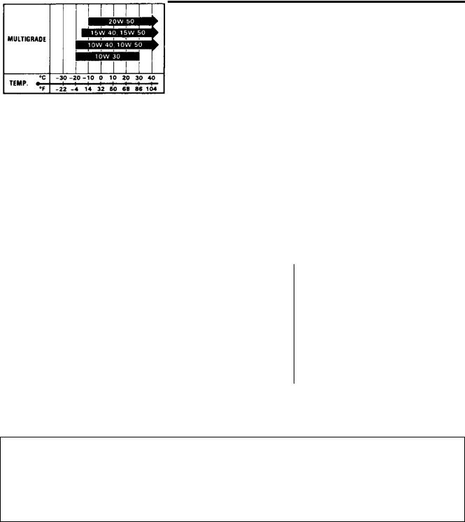
Suzuki recommends the use of SAE 10W-40 engine oil. If SAE 10W-40 engine oil is not available, select an alternative according to the following chart.
ENGINE OIL (FOR OTHER COUNTRIES) |
|
E |
||
Oil quality is a major contributor to your engine’s performance |
||||
and life. Always select good quality engine oil. Use of SF/SG or |
||||
SH/SJ in API with MA in JASO. |
|
L |
||
|
|
|
||
Suzuki recommends the use of SAE 10W-40 engine oil. If SAE |
|
|||
10W-40 engine oil is not available, select an alternative accord- |
|
|||
|
|
P |
|
|
ing to the right chart. |
M |
|
|
|
|
|
|
||
BRAKE FLUID |
A |
|
|
|
|
|
|
||
Specification and classification:SDOT 4 |
|
|
|
|
Since the brake system of this motorcycle is filled with a glycol-based brake fluid by the manufacturer, do not use or mix different types of fluid such as silicone-based and petroleum-based fluid for refilling the system, otherwise serious damage will result.
Do not use any brake fluid taken from old or used or unsealed containers.
Never re-use brake fluid left over from a previous servicing, which has been stored for a long period.
1-6 GENERAL INFORMATION
LIQUID AMOUNT OF WATER/ENGINE COOLANT |
|
Solution capacity (total): Approx. 2 700 ml (2.9/2.4 US/Imp qt) |
|
For engine coolant mixture information, refer to cooling system section in page 7-2. |
|
|
E |
L Mixing of anti-freeze/engine coolant should be limitedPto 60%. Mixing beyond it would reduce
its efficiency. If the anti-freeze/engine coolant mixing ratio is below 50%, rust inhabiting performance is greatly reduced. Be sure to mixMit above 50% even though the atmospheric tempera-
ture does not go down to the freezing point. A S
GENERAL INFORMATION 1-7
BREAK-IN PROCEDURES
During manufacture only the best possible materials are used and all machined parts are finished to a very high standard but it is still necessary to allow the moving parts to “BREAK-IN” before subjecting the engine to maximum stresses. The future performance and reliability of the engine depends on the care and restraint exercised during its early life. The general rules are as follows.
• Keep to these break-in engine speed limits:
Initial |
800 km ( |
500 miles): Below 8 000 r/min |
Up to |
1 600 km (1 |
000 miles): Below 12 000 r/min |
Over to 1 600 km (1 |
000 miles): Below 16 000 r/min |
|
•Upon reaching an odometer reading of 1 600 km (1 000 miles) you can subject the motorcycle to full throttle operation.
However, do not exceed 16 000 r/min at any time.
CYLINDER IDENTIFICATION
The four cylinders of this engine are identified as No. 1, No. 2, No. 3 and No. 4 cylinder, as counted from left |
|||
to right (as viewed by the rider on the seat.) |
|
E |
|
|
|
|
L |
#1 |
|
#2 |
P |
|
M |
||
A |
|
|
|
S |
|
|
#4 |
|
|
|
|
|
|
|
#3 |

1-8 GENERAL INFORMATION
INFORMATION LABELS
|
GSX-R600 |
GSX-R600UE |
GSX-R600UF |
1 Noise label |
A (For E-03, 24, 33) |
|
|
|
|
|
|
2 Information label |
A (For E-03, 28, 33) |
|
|
|
|
|
|
3 Vacuum hose routing label |
A (For E-33) |
|
|
|
|
|
|
4 Fuel caution label |
A (For E-02, 24) |
|
|
|
|
|
|
5 Manual notice label |
A (For E-03, 33) |
|
|
|
|
|
|
6 Screen label |
A (Except E-19 ) |
|
|
|
|
|
|
7 Screen label |
A (For E-28) |
|
A |
|
|
|
|
8 Screen label |
A (For E-19) |
A |
|
|
|
|
|
9 Warning steering label |
A (For E-03, 33) |
|
|
|
|
|
|
0 Warning steering label |
A (Except E-03, 33) |
A |
A |
|
|
|
|
A Tire information label |
A (For E-03, 33) |
|
|
|
|
|
|
B Tire information label |
A (Except E-03, 33) |
A |
A |
|
|
|
|
C General warning label |
A (Except E-19, 28) |
|
|
|
|
|
|
D General warning label |
|
|
A |
E General warning label |
A (For E-28) |
|
E |
|
|
|
|
||
F General warning label |
A (For E-19) |
|
A |
|
|
|
|
|
|
G ICES Canada label |
A (For E-28) |
L |
|
|
|
|
|
||
|
|
|
|
|
H I.D. plate |
P |
A |
A |
|
A (For E-02, 19, 24) |
|
|||
I E-19 I.D. label |
|
|
|
A |
J Safety plate |
M |
|
|
|
A (For E-03, 28, 33) |
|
|
|
|
A: Attached |
A |
|
|
|
*1: Rear fender (front) |
|
|
|
|
S |
|
|
|
|
*2: Chain case |
|
|
|
|
|
|
|
|
|
*2
*1

GENERAL INFORMATION 1-9
SPECIFICATIONS
DIMENSIONS AND DRY MASS
Overall length .......................................................................... |
2 040 mm (80.3 in) |
|
Overall width ........................................................................... |
715 mm (28.1 in) |
|
Overall height .......................................................................... |
1 125 mm (44.3 in) |
|
Wheelbase .............................................................................. |
1 400 mm (55.1 in) |
|
Ground clearance.................................................................... |
130 mm (5.1 in) |
|
Seat height .............................................................................. |
810 mm (31.9 in) |
|
Dry mass ................................................................................. |
162 kg (357 lbs) ........... |
E-33 |
|
161 kg (354 lbs) ........... |
Others |
ENGINE
Type ........................................................................................ |
|
|
|
Four stroke, liquid-cooled, DOHC |
|
Number of cylinders ................................................................ |
|
|
|
4 |
|
Bore......................................................................................... |
|
|
|
67.0 mm (2.638 in) |
|
Stroke ...................................................................................... |
|
|
|
42.5 mm (1.673 in) |
|
Displacement .......................................................................... |
|
|
|
599 cm³ (36.5 cu. in) |
|
Compression ratio ................................................................... |
|
|
|
12.5 : 1 |
|
Fuel system |
|
|
|
E |
|
|
|
|
Fuel injection |
||
Air cleaner |
|
|
|
L |
|
|
|
|
Paper element |
||
Starter system ......................................................................... |
|
|
|
Electric |
|
Lubrication system |
|
|
P |
|
|
|
|
|
Wet sump |
||
Idle speed................................................................................ |
|
M |
1 300 |
± 100 r/min |
|
DRIVE TRAIN |
|
|
|
||
A |
|
|
|
||
Clutch |
|
Wet multi-plate type |
|||
|
|
|
|||
Transmission........................................................................... |
|
|
|
6-speed constant mesh |
|
Gearshift pattern ..................................................................... |
|
|
|
1-down, 5-up |
|
Primary reduction ratio ............................................................S |
|
|
1.974 |
(77/39) |
|
Gear ratios, Low ...................................................................... |
|
|
|
2.785 |
(39/14) |
2nd....................................................................... |
|
|
|
2.052 |
(39/19) |
3rd........................................................................ |
|
|
|
1.714 |
(36/21) |
4th........................................................................ |
|
|
|
1.500 |
(36/24) |
5th........................................................................ |
|
|
|
1.347 |
(31/23) |
Top....................................................................... |
|
|
|
1.208 |
(29/24) |
Final reduction ratio................................................................. |
|
|
|
2.687 |
(43/16) |
Drive chain .............................................................................. |
|
|
|
RK525SMOZ7Y, 114 links |
|

1-10 GENERAL INFORMATION
CHASSIS
Front suspension .................................................................... |
Inverted telescopic, coil spring, oil damped |
Rear suspension ..................................................................... |
Link type, coil spring, oil damped |
Front fork stroke...................................................................... |
120 mm (4.7 in) |
Rear wheel travel .................................................................... |
130 mm (5.1 in) |
Steering angle......................................................................... |
27° |
Caster ..................................................................................... |
23° 45’ |
Trail ......................................................................................... |
97 mm (3.8 in) |
Turning radius ......................................................................... |
3.4 m (11.2 ft) |
Front brake.............................................................................. |
Disc brake, twin |
Rear brake .............................................................................. |
Disc brake |
Front tire size .......................................................................... |
120/70 ZR 17 M/C (58 W), tubeless |
Rear tire size........................................................................... |
180/55 ZR 17 M/C (73 W), tubeless |
ELECTRICAL
Ignition type............................................................................. |
|
Electronic ignition (Transistorized) |
||
Ignition timing.......................................................................... |
|
6° B.T.D.C.at 1 300 r/min |
|
|
Spark plug............................................................................... |
|
NGK CR9E or DENSO U27ESR-N |
||
Battery..................................................................................... |
|
12 V 28.8 kC (8 Ah)/10 HR |
|
|
Generator................................................................................ |
|
Three-phase A.C. generator |
|
|
Main fuse |
|
L |
|
|
|
30 A |
E |
|
|
Fuse ........................................................................................ |
|
10/10/15/15/10/10 A |
|
|
Headlight................................................................................. |
|
12 V 55 W (H7) + 12 V 65 W (H9) |
||
Turn signal light....................................................................... |
|
P12 V 21 W |
|
|
License plate light ................................................................... |
A |
12 V 5 W |
|
|
|
|
|
|
|
Brake light/Taillight.................................................................. |
MLED |
|
|
|
Position light............................................................................ |
S |
12 V 5 W × 2 |
|
|
Speedometer light |
LED |
|
|
|
|
|
|
||
Tachometer light ..................................................................... |
|
LED |
|
|
Neutral indicator light .............................................................. |
|
LED |
|
|
High beam indicator light ........................................................ |
|
LED |
|
|
Turn signal indicator light ........................................................ |
|
LED |
|
|
Fuel level indicator light .......................................................... |
|
LED |
|
|
Oil pressure/Coolant temperature/FI warning light ..................... |
LED |
|
|
|
Engine RPM indicator light...................................................... |
|
LED |
|
|
Immobilizer indicator light ....................................................... |
|
LED ......... |
E-02, 19, 24 |
|
CAPACITIES |
|
|
|
|
Fuel tank, including reserve |
.................................................... |
15.5 L (4.1/3.4 US/lmp gal) ...... |
E-33 |
|
|
|
16.5 L (4.4/3.6 US/lmp gal) ...... |
Others |
|
Engine oil, oil change ............................................................. |
|
2 200 ml (2.3/1.9 US/Imp qt) |
|
|
with filter change .................................................. |
2 500 ml (2.6/2.2 US/lmp qt) |
|
||
overhaul................................................................ |
|
2 900 ml (3.1/2.6 US/lmp qt) |
|
|
Coolant.................................................................................... |
|
2.7 L (2.9/2.4 US/lmp qt) |
|
|
These specifications are subject to change without notice.
PERIODIC MAINTENANCE 2-1
PERIODIC MAINTENANCE
CONTENTS
PERIODIC MAINTENANCE SCHEDULE ....................................................
PERIODIC MAINTENANCE CHART.....................................................
LUBRICATION POINTS ........................................................................
MAINTENANCE AND TUNE-UP PROCEDURES .......................................
AIR CLEANER.......................................................................................
SPARK PLUG........................................................................................
VALVE CLEARANCE............................................................................
ENGINE OIL AND OIL FILTER .............................................................
EXHAUST CONTROL VALVE ..............................................................
FUEL LINE.............................................................................................
ENGINE IDLE SPEED |
........................................................................... |
|
|
|||
THROTTLE VALVE SYNCHRONIZATION ........................................... |
|
|||||
EVAPORATIVE EMISSION ..........CONTROL SYSTEM -33 ONLY) |
||||||
PAIR (AIR SUPPLY) SYSTEM .............................................................. |
|
(E |
||||
THROTTLE CABLE PLAY |
L |
|||||
P |
|
|||||
CLUTCH |
................................................................................................ |
|
|
|
||
COOLING SYSTEM |
|
|
||||
M |
|
|||||
DRIVE CHAIN |
|
|
||||
|
|
|
|
|||
BRAKE .................................................................................................. |
|
A |
|
|
||
TIRES |
|
|
|
|
||
..................................................................................................... |
|
|
|
|
|
|
STEERING............................................................................................. |
|
|
|
|
||
|
SU |
|
|
|
||
FRONT ........................................................................................FORK |
|
|
|
|
||
REAR ............................................................................ |
|
PEN ION |
|
|
|
|
EXHAUST .........................................................PIPE BOLT AND NUT |
|
|
||||
CHASSIS ..............................................................BOLTS AND NUTS |
|
|
||||
COMPRESSION PRESSURE CHECK ........................................................
COMPRESSION TEST PROCEDURE ..................................................
OIL PRESSURE CHECK .............................................................................
SDS CHECK.................................................................................................
2- |
2 |
|
|
|
2 |
||
2- |
2 |
|
|
2- |
3 |
|
|
|
|||
2- |
4 |
|
|
2- |
4 |
|
|
2- |
5 |
|
|
2- |
7 |
|
|
2-12 |
|
|
|
2-13 |
|
|
|
2-14 |
|
|
|
2-14 |
|
|
|
2-15 |
|
|
|
2-15 |
|
|
|
2-15 |
|
|
|
2-15 |
|
|
|
2-16 |
|
|
|
2-17 |
|
|
|
2-20 |
|
|
|
2-23 |
|
|
|
2-27 |
|
|
|
2-27 |
|
|
|
2-28 |
|
|
|
2-28 |
|
|
|
2-29 |
|
|
|
2-30 |
|
|
|
2-32 |
|
|
|
2-32 |
|
|
|
2-33 |
|
|
|
2-34 |
|
|
|
|
|
|
|
2-2 PERIODIC MAINTENANCE
PERIODIC MAINTENANCE SCHEDULE
The chart below lists the recommended intervals for all the required periodic service work necessary to keep the motorcycle operating at peak performance and economy. Mileages are expressed in terms of kilometers, miles and time for your convenience.
IMPORTANT (For E-28): The periodic maintenance intervals and service requirements have been established in accordance with EPA regulations. Following these instructions will ensure that the motorcycle will not exceed emission standards and it will also ensure the reliability and performance of the motorcycle.
NOTE:
More frequent servicing may be required on motorcycles that are used under severe conditions.
PERIODIC MAINTENANCE CHART
|
Interval |
miles |
600 |
4 000 |
|
7 500 |
11 000 |
14 500 |
|
|
km |
1 000 |
6 000 |
12 000 |
18 000 |
24 000 |
|
Item |
|
months |
2 |
12 |
|
24 |
36 |
48 |
Air cleaner element |
|
|
---- |
I |
|
I |
R |
I |
Spark plugs |
|
|
---- |
I |
|
R |
I |
R |
Valve clearance |
|
|
---- |
---- |
|
---- |
---- |
I |
Exhaust control valve |
|
|
I |
---- |
|
I |
---- |
I |
Engine oil |
|
|
R |
R |
|
R |
R |
R |
Engine oil filter |
|
|
R |
---- |
|
---- |
R |
---- |
|
|
|
|
|
E |
|
|
|
Fuel line |
|
|
---- |
I |
|
I |
I |
I |
Idle speed |
|
|
I |
L |
I |
I |
I |
|
|
|
I |
|
|||||
|
|
|
I |
|
|
|
|
|
Throttle valve synchronization |
|
P |
|
I |
---- |
I |
||
|
(E-33 only) |
---- |
|
|||||
Evaporative emission control system |
M |
---- |
|
I |
---- |
I |
||
|
|
|
||||||
(E-33 only) |
A |
---- |
|
|||||
|
|
|
|
|
|
|||
PAIR (air supply) system |
---- |
---- |
|
I |
---- |
I |
||
Throttle cable play |
S |
|
I |
I |
|
I |
I |
I |
Clutch cable play |
|
---- |
I |
|
I |
I |
I |
|
|
|
|
||||||
Radiator hoses |
|
|
---- |
I |
|
I |
I |
I |
Engine coolant |
|
|
|
Replace every 2 years. |
|
|||
Drive chain |
|
|
I |
I |
|
I |
I |
I |
|
|
|
Clean and lubricate every 1 000 km (600 miles). |
|||||
Brakes |
|
|
I |
I |
|
I |
I |
I |
|
|
|
---- |
I |
|
I |
I |
I |
Brake hoses |
|
|
|
|
|
|
Replace every 4 years. |
|
|||
|
|
|
|||
|
|
|
|
|
|
Brake fluid |
---- |
I |
I |
I |
I |
|
|
|
|
|
|
|
Replace every 2 years. |
|
|||
|
|
|
|||
|
|
|
|
|
|
Tires |
---- |
I |
I |
I |
I |
|
|
|
|
|
|
Steering |
I |
---- |
I |
---- |
I |
|
|
|
|
|
|
Front forks |
---- |
---- |
I |
---- |
I |
|
|
|
|
|
|
Rear suspension |
---- |
---- |
I |
---- |
I |
|
|
|
|
|
|
Exhaust pipe bolts and muffler bolt and nut |
T |
---- |
T |
---- |
T |
|
|
|
|
|
|
Chassis bolts and nuts |
T |
T |
T |
T |
T |
|
|
|
|
|
|
NOTE:
I = Inspect and clean, adjust, replace or lubricate as necessary; R = Replace; T = Tighten

PERIODIC MAINTENANCE 2-3
LUBRICATION POINTS
Proper lubrication is important for smooth operation and long life of each working part of the motorcycle. Major lubrication points are indicated below.
 Brake lever holder
Brake pedal pivot and footrestEpivot |
L |
P |
Clutch lever holder |
M |
A |
S |
Footrest pivot and |
Side-stand pivot |
Drive chain |
|
gearshift lever pivot |
|||
and spring hook |
|||
|
|
NOTE:
*Before lubricating each part, clean off any rusty spots and wipe off any grease, oil, dirt or grime.
*Lubricate exposed parts which are subject to rust, with a rust preventative spray whenever the motorcycle has been operated under wet or rainy conditions.
2-4 PERIODIC MAINTENANCE
MAINTENANCE AND TUNE-UP PROCEDURES
This section describes the servicing procedures for each item of the Periodic Maintenance requirements.
AIR CLEANER
Inspect every 6 000 km (4 000 miles, 12 months).
Replace every 18 000 km (11 000 miles, 36 months).
• Remove the front seat. ( 8-7)
• Lift and support the fuel tank. ( 5-3)
• Remove the air cleaner element by removing the screws.
• Remove the air cleaner element. |
|
|
|
||
• Inspect the air cleaner element for clogging. |
|
|
E |
||
If the air cleaner element is clogged with dust, replace the air |
|||||
|
|||||
cleaner element with a new one. |
|
|
|
||
|
|
|
|
|
|
|
|
|
|
||
|
P |
|
|||
Do not blow the air cleaner element with compressed |
L |
||||
air. |
M |
|
|
|
|
|
|
|
|
||
NOTE: |
|
|
|
||
A |
|
|
|
||
|
|
|
|
||
If driving under dusty conditions, replace the air cleaner element |
|
||||
more frequently. Make sure that the air cleaner is in good condi- |
|
||||
tion at all times. The life of the engine depends largely on this |
|
||||
component. |
S |
|
|
|
|
•Install a new air cleaner element in the reverse order of removal.
•Remove the drain plug from the air cleaner box to allow any water to drain out.

PERIODIC MAINTENANCE 2-5
SPARK PLUG
Inspect every 6 000 km (4 000 miles, 12 months).
Replace every 12 000 km (7 500 miles, 24 months).
SPARK PLUG AND IGNITION COIL/PLUG CAP REMOVAL
•Remove the front seat. ( 8-7)
•Lift and support the fuel tank. ( 5-3)
•Remove the air cleaner box. ( 5-14)
•Disconnect all lead wire couplers from ignition coil/plug caps.
Disconnect the lead wire coupler before removing the ignition coil/plug cap to avoid lead wire coupler damage.
• Remove the ignition coils/plug caps.
|
|
|
|
E |
* Do not pry up the ignition coil/plug cap with a screw |
|
|||
driver or a bar to avoid its damage. |
L |
|||
|
|
|
||
* Be careful not to drop the ignition coil/plug cap to |
|
|||
prevent short/open circuit. |
|
|
|
|
|
|
|
|
|
|
M |
|
|
|
• Remove the spark plugs with a spark plug wrench.P |
|
|||
HEAT RANGE |
|
|
|
|
• Check spark plug heat range by observing electrode color. If |
|
|||
S |
|
|
|
|
the electrode of the spark Aplug is wet appearing or dark color, |
|
|||
replace the spark plug with hotter type one. If it is white or |
|
|||
glazed appearing, replace the spark plug with colder type |
|
|||
one.
|
Hot type |
Standard |
Cold type |
|
|
|
|
NGK |
CR8E |
CR9E |
CR10E |
|
|
|
|
ND |
U24ESR-N |
U27ESR-N |
U31ESR-N |
NOTE:
“R” type spark plug has a resistor built into at the center electrode to prevent radio noise.
CARBON DEPOSITS
•Check carbon deposits on the spark plug.
•If carbon is deposited, remove it using a spark plug cleaner machine or carefully use a tool with a pointed end.

2-6 PERIODIC MAINTENANCE
SPARK PLUG GAP
•Measure the spark plug gap with a thickness gauge.
•Adjust the spark plug gap if necessary.
Spark plug gap:
Standard: 0.7 – 0.8 mm (0.028 – 0.031 in)
09900-20803: Thickness gauge
ELECTRODE’S CONDITION
•Check the condition of the electrode.
•If it is extremely worn or burnt, replace the spark plug. Replace the spark plug if it has a broken insulator, damaged thread, etc.
Confirm the thread size and reach when replacing the plug. If the reach is too short, carbon will be deposited on the screw portion of the plug hole and engine damage may result.
SPARK PLUG AND IGNITION COIL/PLUG CAP |
|
|
|
E |
|
INSTALLATION |
|
|
|
|
|
• Screw the spark plugs into the cylinder head with fingers, and |
|||||
then tighten them to the specified torque. |
|
L |
|||
Spark plug: 11 N·m (1.1 kgf-m, 8.0 Ib-ft) |
P |
|
|||
|
|
|
|||
M |
|
|
|
||
|
|
|
|
||
Do not cross thread or over tighten the spark plug, or |
|
|
|
||
such an operation will damage the aluminum threads |
|
|
|
||
of the cylinder head. |
A |
|
|
|
|
S |
|
|
|
|
|
|
|
|
|
|
|
•Install the ignition coils/plug caps and connect their lead wire couplers.
*Do not hit the ignition coil/plug cap with a plastic hammer when installing it.
*Place the ignition coil/spark plug cap so that the coupler does not touch the cylinder head cover.
CONTACT
INCORRECT INCORRECT
PERIODIC MAINTENANCE 2-7
VALVE CLEARANCE
Inspect every 24 000 km (14 500 miles, 48 months).
• Remove the right under cowling. ( 8-5)
• Lift and support the fuel tank. ( 5-3)
•Remove the air cleaner box. ( 5-14)
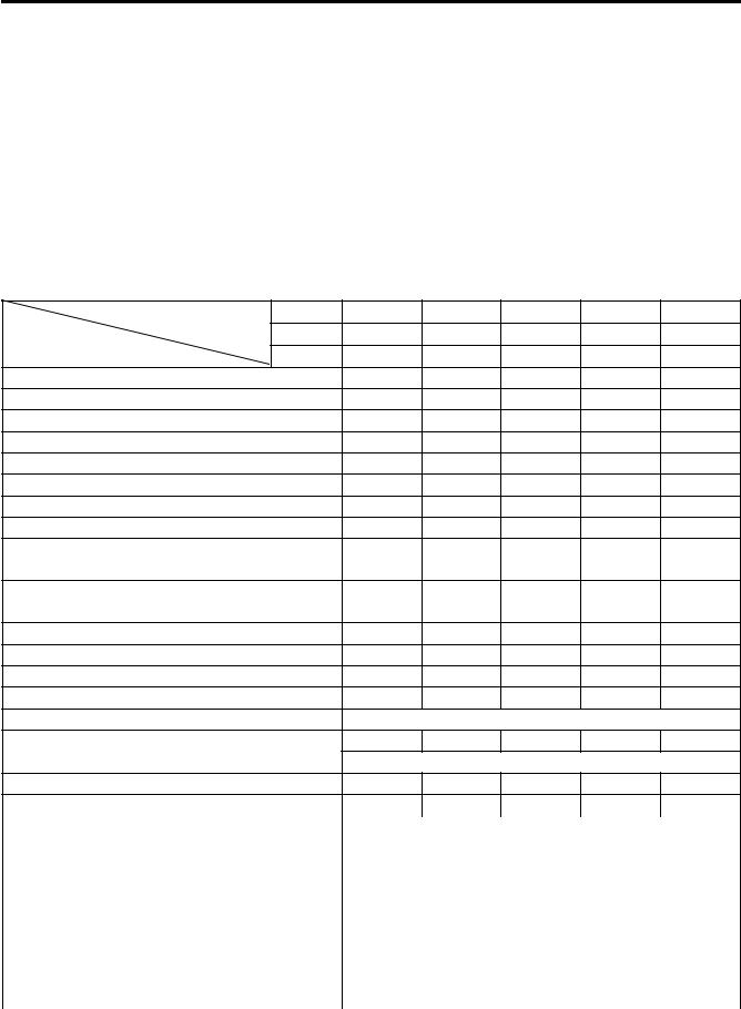
•Disconnect the CMP sensor coupler 1.
•Remove the PAIR control solenoid valve 2.
•Remove the spark plugs. ( 2-5)
•Loosen the throttle body clamp screws at the intake pipe side.
•Move the throttle body assembly.
•Move the radiator forward. ( 6-10)
•Remove the regulator/rectifier and horn. ( 3-6)
•Remove the cylinder head cover. ( 3-14)
|
|
|
E |
|
|
|
|
L |
|
||
The valve clearance specification is different for intake and |
|
|
|
||
exhaust valves. Valve clearance must be checked and adjusted, |
|
|
|
||
|
|
P |
|
|
|
1) at the time of periodic inspection, 2) when the valve mecha- |
|
|
|
||
nism is serviced, and 3) when the camshafts are removed for |
|
|
|
||
servicing. |
|
M |
|
|
|
|
A |
|
|
|
|
Valve clearance (when cold): |
|
|
|
|
|
Standard: IN. : 0.08 – 0.18 mm (0.003 – 0.007 in) |
|
|
|
||
|
EX. : 0.18 – 0.28 mm (0.007 – 0.011 in) |
|
|
|
|
NOTE: |
S |
|
|
|
|
|
|
|
|
||
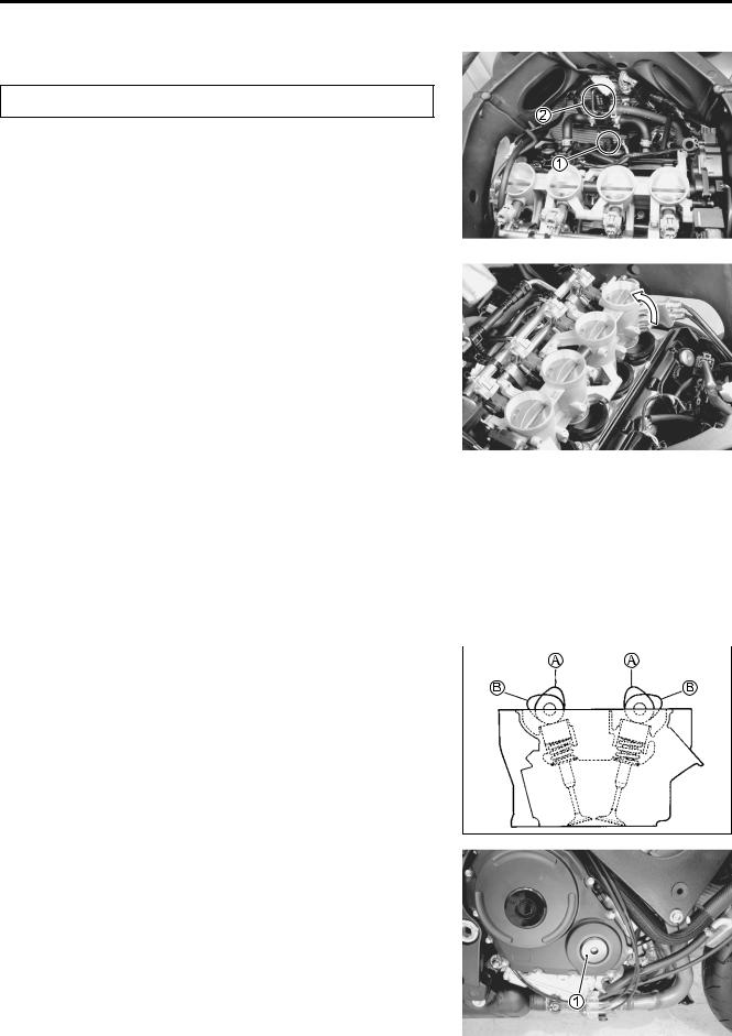
* The cam must be at positions, A or B, when checking or |
|
|
|
||
adjusting the valve clearance. Clearance readings should not |
|
|
EX. IN. |
||
be taken with the cam in any other position than these two |
|
|
|
||
positions. |
|
|
|
|
|
*The clearance specification is for COLD state.
*To turn the crankshaft for clearance checking, be sure to use a wrench, and rotate in the normal running direction. All spark plugs should be removed.
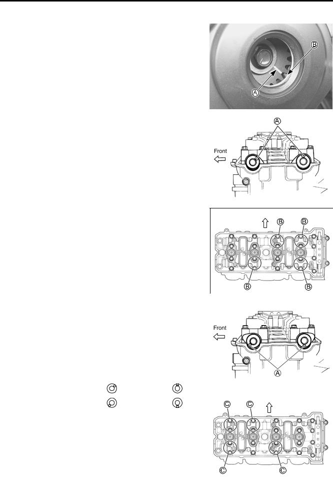
•Remove the valve timing inspection cap 1.
2-8 PERIODIC MAINTENANCE
•Turn the crankshaft to bring the line A on the CKP sensor rotor to the rib B behind the clutch cover and also to bring the
notches A on the left ends of both camshafts (Ex. and In.) to the positions as shown.
|
|
|
|
|
|
|
|
|
|
|
|
|
|
|
|
|
|
|
|
|
|
|
|
|
|
|
|
|
|
|
|
E |
|
|
|
|
|
|
|
|
|
|
||
|
|
|
L |
Front |
|
|
||
• In this condition, read the valve clearance at the valves B (In. |
|
|
|
|||||
and Ex. of No. 4 cylinder, Ex. of No. 3 and In. of No. 2). |
|
|
|
|
|
|
||
|
|
P |
|
|
|
|
||
• If the clearance is out of specification, adjust the clearance. |
|
|
|
|
|
|
||
( 2-9) |
|
M |
|
|
|
|
|
|
09900-20803: Thickness gauge |
|
|
|
|
|
|
||
|
A |
|
|
|
|
|
|
|
|
S |
|
|
|
|
|
|
|
|
|
|
|
|
|
|
|
|
|
|
|
|
|
|
|
|
|
• Turn the crankshaft 360 degrees (one rotation) to bring the |
|
|
|
|
||||
line on the CKP sensor rotor to the index mark of valve timing |
|
|
|
|
||||
inspection hole and also to bring the notches A to the posi- |
|
|
|
|
||||
tion as shown. |
|
|
|
|
|
|
|
|
• Read the clearance at the rest of the valves C and adjust the |
|
|
|
|
||||
clearance if necessary. ( 2-9) |
|
|
|
|
|
|
|
|
|
|
|
|
|
|
|
|
|
|
|
|
|
|
|
|
|
|
Cam position |
Notch A position |
|
|
|
|
|
|
|
|
|
|
|
|
|
|
|
|
Exhaust Camshaft |
Intake Camshaft |
|
|
|
|
|
|
|
|
|
|
|
|
|
|
||
|
|
|
|
|
|
|
|
|
B |
← Front |
← Front |
|
|
|
|
|
|
|
|
|
|
|
|
|||
C |
← Front |
← Front |
|
|
|
Front |
|
|
|
|
|
|
|
|
|||
|
|
|
|
|
|
|
|
|
|
|
|
|
|
|
|
|
|
PERIODIC MAINTENANCE 2-9
VALVE CLEARANCE ADJUSTMENT
The clearance is adjusted by replacing the existing tappet shim by a thicker or thinner shim.
•Remove the intake or exhaust camshafts. ( 3-14)
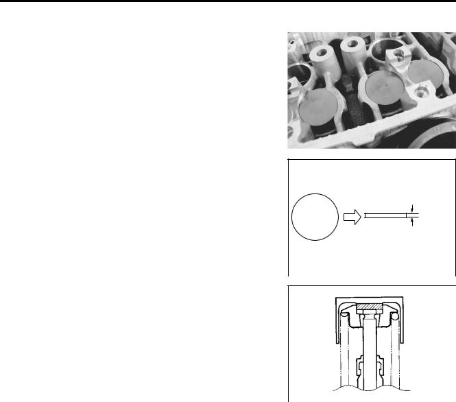
•Remove the tappet and shim by fingers or magnetic hand.
•Check the figures printed on the shim. These figures indicate the thickness of the shim, as illustrated.
•Select a replacement shim that will provide a clearance within the specified range. For the purpose of this adjustment, a total of 21 sizes of tappet shim are available ranging from 1.20 to 2.20 mm in steps of 0.05 mm. Fit the selected shim to the valve stem end, with numbers toward tappet. Be sure to
check shim size with micrometer to ensure its size. Refer to the tappet shim selection table ( 2-10 and -11) for details.
170 |
1.70 mm |
|
|
|
|
|
|
|
|
|
E |
|
|
|
|
|
|
|||
NOTE: |
L |
|
|
||
* Be sure to apply engine oil to tappet shim top and bottom |
|
|
|
|
|
faces. |
|
|
|
|
|
* When seating the tappet shim, be sure the figure printed sur- |
|
|
|
|
|
face faces the tappet. |
M |
|
|
|
|
P |
|
|
|
|
|
NOTE: |
|
|
|
|
|
Reinstall the camshafts in the specified manner. ( 3-92) |
|
|
|
|
|
S |
|
|
|
|
|
• After replacing the tappetAshim and camshafts, rotate the |
|
|
|
|
|
engine so that the tappet is depressed fully. This will squeeze |
|
|
|
|
|
|
|
|
|
||
out oil trapped between the shim and the tappet that could |
|
|
|
|
|
cause an incorrect measurement. Then check the clearance |
|
|
|
|
|
again to confirm that it is within the specified range. |
|
|
|
|
|
• After finishing the valve clearance adjustment, reinstall the following items.
*Cylinder head cover ( 3-97)
*Spark plug and plug cap ( 2-6)
*Throttle body assembly ( 5-21)
*Valve timing inspection plug ( 3-97)
*PAIR control solenoid valve ( 11-7)
TAPPET SHIM SELECTION TABLE [INTAKE]
TAPPET SHIM NO. (12892-05C00-XXX)
TAPPET SHIM SET (12800-05830)
|
SUFFIX |
120 |
125 |
130 |
135 |
S |
150 |
155 |
160 |
165 |
170 |
175 |
180 |
185 |
190 |
195 |
200 |
205 |
|
210 |
215 |
220 |
|
||
|
140 |
145 |
|
|
|||||||||||||||||||||
|
|
NO. |
|
|
|
|
|
|
|
|
|
|
|
|
|
|
|
|
|
|
|
|
|
|
|
MEASURED |
|
|
|
|
|
|
|
|
|
|
|
|
|
|
|
|
|
|
|
|
|
|
|
|
|
PRESENT |
|
|
|
|
|
|
|
|
|
|
|
|
|
|
|
|
|
|
|
|
|
|
|
||
VALVE |
|
|
|
|
|
A |
|
|
|
|
|
|
|
|
|
|
|
|
|
|
|
|
|||
SHIM SIZE |
|
|
|
|
|
|
|
|
|
|
|
|
|
|
|
|
|
|
|
|
|
||||
CLEARANCE |
|
|
|
|
|
|
|
|
|
|
|
|
|
|
|
|
|
|
|
|
|
||||
|
(mm) |
|
|
|
|
|
|
|
|
|
|
|
|
|
|
|
|
|
|
|
|
|
|||
(mm) |
|
1.20 |
1.25 |
1.30 |
1.35 |
1.40 |
1.45 |
1.50 |
1.55 |
1.60 |
1.65 |
1.70 |
1.75 |
1.80 |
1.85 |
1.90 |
1.95 |
2.00 |
2.05 |
|
2.10 |
2.15 |
2.20 |
|
|
|
|
|
|
|
|
|
|
|
|
|
|
|
|
|
|
|
|
|
|
|
|
|
|
|
|
0.00 – 0.04 |
|
|
|
|
1.20 |
1.25 |
1.30 |
1.35 |
1.40 |
1.45 |
1.50 |
1.55 |
1.60 |
1.65 |
1.70 |
1.75 |
1.80 |
1.85 |
1.90 |
1.95 |
|
2.00 |
2.05 |
2.10 |
|
|
|
|
|
|
|
|
|
|
|
|
|
|
|
|
|
|
|
|
|
|
|
|
|
|
|
0.05 – 0.09 |
|
|
|
1.20 |
1.25 |
1.30 |
1.35 |
1.40 |
1.45 |
1.50 |
1.55 |
1.60 |
1.65 |
1.70 |
1.75 |
1.80 |
1.85 |
1.90 |
1.95 |
2.00 |
|
2.05 |
2.10 |
2.15 |
|
|
|
|
|
|
|
|
|
|
|
|
|
|
|
|
|
|
|
|
|
|
|
|
|
|
|
0.10 – 0.20 |
|
|
|
|
|
|
|
|
M |
|
|
ADJUSTMENT REQUIRED |
|
|
|
|
|
|
|
|
|||||
|
|
|
|
|
|
|
|
SPECIFIED CLEARANCE/NO |
|
|
|
|
|
|
|
|
|||||||||
0.21 – 0.25 |
|
|
1.30 |
1.35 |
1.40 |
1.45 |
1.50 |
1.55 |
1.60 |
1.65 |
1.70 |
1.75 |
1.80 |
1.85 |
1.90 |
1.95 |
2.00 |
2.05 |
2.10 |
2.15 |
|
2.20 |
2.20 |
|
|
0.26 – 0.30 |
|
|
1.35 |
1.40 |
1.45 |
1.50 |
1.55 |
1.60 |
1.65 |
1.70 |
1.75 |
1.80 |
1.85 |
1.90 |
1.95 |
2.00 |
2.05 |
2.10 |
2.15 |
2.20 |
|
|
|
|
|
0.31 – 0.35 |
|
|
1.40 |
1.45 |
1.50 |
1.55 |
1.60 |
1.65 |
1.70 |
1.75 |
1.80 |
1.85 |
1.90 |
1.95 |
2.00 |
2.05 |
2.10 |
2.15 |
2.20 |
|
|
|
|
|
|
|
|
|
|
|
|
|
|
|
|
|
|
|
|
|
|
|
|
|
|
|
|
|
|
|
|
0.36 – 0.40 |
|
|
1.45 |
1.50 |
1.55 |
1.60 |
1.65 |
1.70 |
1.75 |
1.80 |
1.85 |
1.90 |
1.95 |
2.00 |
2.05 |
2.10 |
2.15 |
2.20 |
|
|
|
|
|
|
|
|
|
|
|
|
|
|
|
|
|
|
|
|
|
|
|
|
|
|
|
|
|
|
|
|
|
0.41 – 0.45 |
|
|
1.50 |
1.55 |
1.60 |
1.65 |
1.70 |
1.75 |
1.80 |
1.85 |
1.90 |
1.95 |
2.00 |
2.05 |
2.10 |
2.15 |
2.20 |
|
|
|
|
|
|
|
|
|
|
|
|
|
|
|
|
|
|
|
|
|
|
|
|
|
|
|
|
|
|
|
|
|
|
0.46 – 0.50 |
|
|
1.55 |
1.60 |
1.65 |
1.70 |
1.75 |
1.80 |
1.85 |
1.90 |
1.95 |
2.00 |
2.05 |
2.10 |
2.15 |
2.20 |
|
|
|
|
|
|
|
|
|
|
|
|
|
|
|
|
|
|
|
|
|
|
|
|
|
|
|
|
|
|
|
|
|
|
|
0.51 – 0.55 |
|
|
1.60 |
1.65 |
1.70 |
1.75 |
1.80 |
1.85 |
1.90 |
1.95 |
2.00 |
2.05 |
2.10 |
2.15 |
2.20 |
|
|
|
|
|
|
|
|
|
|
|
|
|
|
|
|
|
|
|
|
|
P |
|
|
|
|
|
|
|
|
|
|
|
|
|
|
0.56 – 0.60 |
|
|
1.65 |
1.70 |
1.75 |
1.80 |
1.85 |
1.90 |
1.95 |
2.00 |
2.05 2.10 |
2.15 |
2.20 |
|
|
|
|
|
|
|
|
|
|
|
|
|
|
|
|
|
|
|
|
|
|
|
|
|
|
|
|
|
|
|
|
|
|
|
|
|
|
0.61 – 0.65 |
|
|
1.70 |
1.75 |
1.80 |
1.85 |
1.90 |
1.95 |
2.00 |
2.05 |
2.10 |
2.15 |
2.20 |
|
|
|
|
|
|
|
|
|
|
|
|
|
|
|
|
|
|
|
|
|
|
|
|
|
|
|
|
|
|
|
|
|
|
|
|
|
|
0.66 – 0.70 |
|
|
1.75 |
1.80 |
1.85 |
1.90 |
1.95 |
2.00 |
2.05 |
2.10 |
2.15 |
2.20 |
E |
|
|
|
|
|
|
|
|
|
|
|
|
|
|
|
|
|
|
|
|
|
|
|
L |
|
|
|
|
|
|
|
|
|
|
|
|
||
0.71 – 0.75 |
|
|
1.80 |
1.85 |
1.90 |
1.95 |
2.00 |
2.05 |
2.10 |
2.15 |
2.20 |
|
|
|
|
|
|
|
|
|
|
|
|
|
|
|
|
|
|
|
|
|
|
|
|
|
|
|
|
|
|
|
|
|
|
|
|
|
|
|
|
0.76 – 0.80 |
|
|
1.85 |
1.90 |
1.95 |
2.00 |
2.05 |
2.10 |
2.15 |
2.20 |
|
|
|
|
|
|
|
|
|
|
|
|
|
|
|
|
|
|
|
|
|
|
|
|
|
|
|
|
|
|
|
|
|
|
|
|
|
|
|
|
|
0.81 – 0.85 |
|
|
1.90 |
1.95 |
2.00 |
2.05 |
2.10 |
2.15 |
2.20 |
|
|
|
|
|
|
|
|
|
|
|
|
|
|
|
|
|
|
|
|
|
|
|
|
|
|
|
|
|
|
|
|
|
|
|
|
|
|
|
|
|
|
0.86 – 0.90 |
|
|
1.95 |
2.00 |
2.05 |
2.10 |
2.15 |
2.20 |
|
|
|
|
|
|
|
|
|
|
|
|
|
|
|
|
|
|
|
|
|
|
|
|
|
|
|
|
|
|
|
|
|
|
|
|
|
|
|
|
|
|
|
0.91 – 0.95 |
|
|
2.00 |
2.05 |
2.10 |
2.15 |
2.20 |
|
|
|
|
HOW TO USE THIS CHART: |
|
|
|
|
|
|
|
|
|||||
|
|
|
|
|
|
|
|
|
|
|
|
|
|
|
|
|
|
|
|
||||||
0.96 – 1.00 |
|
|
2.05 |
2.10 |
2.15 |
2.20 |
|
|
|
|
|
|
|
|
|
|
|
|
|
||||||
|
|
|
|
|
|
|
|
|
|
|
|
I. |
Measure valve clearance. “ENGINE IS COLD” |
|
|
|
|
||||||||
1.01 – 1.05 |
|
|
2.10 |
2.15 |
2.20 |
|
|
|
|
|
|
|
|
|
|
||||||||||
|
|
|
|
|
|
|
|
II. |
Measure present shim size. |
|
|
|
|
|
|
|
|
||||||||
|
|
|
|
|
|
|
|
|
|
|
|
|
|
|
|
|
|
|
|
||||||
1.06 – 1.10 |
|
|
2.15 |
2.20 |
|
|
|
|
|
|
|
|
|
|
|
|
|
|
|
||||||
|
|
|
|
|
|
|
|
|
III. Match clearance in vertical column with present shim size in horizontal |
||||||||||||||||
|
|
|
|
|
|
|
|
|
|
|
|
||||||||||||||
1.11 – 1.15 |
|
|
2.20 |
|
|
|
|
|
|
|
|
||||||||||||||
|
|
|
|
|
|
|
|
|
|
|
column. |
|
|
|
|
|
|
|
|
|
|
|
|||
|
|
|
|
|
|
|
|
|
|
|
|
|
|
|
|
|
|
|
|
|
|
|
|
||
|
|
|
|
|
|
|
|
|
|
|
|
|
|
EXAMPLE |
|
|
|
|
|
|
|
|
|
||
|
|
|
|
|
|
|
|
|
|
|
|
|
Valve clearance is |
|
0.23 mm |
|
|
|
|
|
|
||||
|
|
|
|
|
|
|
|
|
|
|
|
|
Present shim size |
|
1.70 mm |
|
|
|
|
|
|
||||
|
|
|
|
|
|
|
|
|
|
|
|
|
Shim size to be used |
|
1.80 mm |
|
|
|
|
|
|
||||
SIDE)(INTAKE |
MAINTENANCE PERIODIC 10-2 |
|
|
TAPPET SHIM SELECTION TABLE [EXHAUST]
TAPPET SHIM NO. (12892-05C00-XXX)
TAPPET SHIM SET (12800-05830)
|
SUFFIX |
120 |
125 |
130 |
135 |
S |
150 |
155 |
160 |
165 |
170 |
175 |
180 |
185 |
190 |
195 |
200 |
205 |
|
210 |
215 |
220 |
|
||
|
140 |
145 |
|
|
|||||||||||||||||||||
|
|
NO. |
|
|
|
|
|
|
|
|
|
|
|
|
|
|
|
|
|
|
|
|
|
|
|
MEASURED |
|
|
|
|
|
|
|
|
|
|
|
|
|
|
|
|
|
|
|
|
|
|
|
|
|
PRESENT |
|
|
|
|
|
|
|
|
|
|
|
|
|
|
|
|
|
|
|
|
|
|
|
||
VALVE |
|
|
|
|
|
A |
|
|
|
|
|
|
|
|
|
|
|
|
|
|
|
|
|||
SHIM SIZE |
|
|
|
|
|
|
|
|
|
|
|
|
|
|
|
|
|
|
|
|
|
||||
CLEARANCE |
|
|
|
|
|
|
|
|
|
|
|
|
|
|
|
|
|
|
|
|
|
||||
|
(mm) |
|
|
|
|
|
|
|
|
|
|
|
|
|
|
|
|
|
|
|
|
|
|||
(mm) |
|
1.20 |
1.25 |
1.30 |
1.35 |
1.40 |
1.45 |
1.50 |
1.55 |
1.60 |
1.65 |
1.70 |
1.75 |
1.80 |
1.85 |
1.90 |
1.95 |
2.00 |
2.05 |
|
2.10 |
2.15 |
2.20 |
|
|
|
|
|
|
|
|
|
|
|
|
|
|
|
|
|
|
|
|
|
|
|
|
|
|
|
|
0.05 – 0.09 |
|
|
|
|
|
1.20 |
1.25 |
1.30 |
1.35 |
1.40 |
1.45 |
1.50 |
1.55 |
1.60 |
1.65 |
1.70 |
1.75 |
1.80 |
1.85 |
1.90 |
|
1.95 |
2.00 |
2.05 |
|
0.10 – 0.14 |
|
|
|
|
1.20 |
1.25 |
1.30 |
1.35 |
1.40 |
1.45 |
1.50 |
1.55 |
1.60 |
1.65 |
1.70 |
1.75 |
1.80 |
1.85 |
1.90 |
1.95 |
|
2.00 |
2.05 |
2.10 |
|
|
|
|
|
|
|
|
|
|
|
|
|
|
|
|
|
|
|
|
|
|
|
|
|
|
|
0.15 – 0.19 |
|
|
|
1.20 |
1.25 |
1.30 |
1.35 |
1.40 |
1.45 |
M |
1.55 |
1.60 |
1.65 |
1.70 |
1.75 |
1.80 |
1.85 |
1.90 |
1.95 |
2.00 |
2.05 |
2.10 |
2.15 |
|
|
|
|
|
1.50 |
|
|||||||||||||||||||||
0.20 – 0.30 |
|
|
|
|
|
|
|
|
SPECIFIED CLEARANCE/NO |
ADJUSTMENT REQUIRED |
|
|
|
|
|
|
|
|
|||||||
0.31 – 0.35 |
|
|
1.30 |
1.35 |
1.40 |
1.45 |
1.50 |
1.55 |
1.60 |
1.65 |
1.70 |
1.75 |
1.80 |
1.85 |
1.90 |
1.95 |
2.00 |
2.05 |
2.10 |
2.15 |
|
2.20 |
2.20 |
|
|
0.36 – 0.40 |
|
|
1.35 |
1.40 |
1.45 |
1.50 |
1.55 |
1.60 |
1.65 |
1.70 |
1.75 |
1.80 |
1.85 |
1.90 |
1.95 |
2.00 |
2.05 |
2.10 |
2.15 |
2.20 |
|
|
|
|
|
0.41 – 0.45 |
|
|
1.40 |
1.45 |
1.50 |
1.55 |
1.60 |
1.65 |
1.70 |
1.75 |
1.80 |
1.85 |
1.90 |
1.95 |
2.00 |
2.05 |
2.10 |
2.15 |
2.20 |
|
|
|
|
|
|
|
|
|
|
|
|
|
|
|
|
|
|
|
|
|
|
|
|
|
|
|
|
|
|
|
|
0.46 – 0.50 |
|
|
1.45 |
1.50 |
1.55 |
1.60 |
1.65 |
1.70 |
1.75 |
1.80 |
1.85 |
1.90 |
1.95 |
2.00 |
2.05 |
2.10 |
2.15 |
2.20 |
|
|
|
|
|
|
|
|
|
|
|
|
|
|
|
|
|
|
|
|
|
|
|
|
|
|
|
|
|
|
|
|
|
0.51 – 0.55 |
|
|
1.50 |
1.55 |
1.60 |
1.65 |
1.70 |
1.75 |
1.80 |
1.85 |
1.90 |
1.95 |
2.00 |
2.05 |
2.10 |
2.15 |
2.20 |
|
|
|
|
|
|
|
|
|
|
|
|
|
|
|
|
|
|
|
|
|
|
|
|
|
|
|
|
|
|
|
|
|
|
0.56 – 0.60 |
|
|
1.55 |
1.60 |
1.65 |
1.70 |
1.75 |
1.80 |
1.85 |
1.90 |
1.95 |
2.00 |
2.05 |
2.10 |
2.15 |
2.20 |
|
|
|
|
|
|
|
|
|
|
|
|
|
|
|
|
|
|
|
|
P |
|
|
|
|
|
|
|
|
|
|
|
|
|
|
0.61 – 0.65 |
|
|
1.60 |
1.65 |
1.70 |
1.75 |
1.80 |
1.85 |
1.90 |
1.95 |
2.00 2.05 |
2.10 |
2.15 |
2.20 |
|
|
|
|
|
|
|
|
|
|
|
|
|
|
|
|
|
|
|
|
|
|
|
|
|
|
|
|
|
|
|
|
|
|
|
|
|
0.66 – 0.70 |
|
|
1.65 |
1.70 |
1.75 |
1.80 |
1.85 |
1.90 |
1.95 |
2.00 |
2.05 |
2.10 |
2.15 |
2.20 |
|
|
|
|
|
|
|
|
|
|
|
|
|
|
|
|
|
|
|
|
|
|
|
|
|
|
|
|
|
|
|
|
|
|
|
|
|
0.71 – 0.75 |
|
|
1.70 |
1.75 |
1.80 |
1.85 |
1.90 |
1.95 |
2.00 |
2.05 |
2.10 |
2.15 |
E |
|
|
|
|
|
|
|
|
|
|
|
|
|
|
2.20 |
|
|
|
|
|
|
|
|
|
|
|
|
|||||||||||
|
|
|
|
|
|
|
|
|
|
|
L |
|
|
|
|
|
|
|
|
|
|
|
|
||
0.76 – 0.80 |
|
|
1.75 |
1.80 |
1.85 |
1.90 |
1.95 |
2.00 |
2.05 |
2.10 |
2.15 2.20 |
|
|
|
|
|
|
|
|
|
|
|
|
|
|
0.81 – 0.85 |
|
|
1.80 |
1.85 |
1.90 |
1.95 |
2.00 |
2.05 |
2.10 |
2.15 |
2.20 |
|
|
|
|
|
|
|
|
|
|
|
|
|
|
0.86 – 0.90 |
|
|
1.85 |
1.90 |
1.95 |
2.00 |
2.05 |
2.10 |
2.15 |
2.20 |
|
|
|
|
|
|
|
|
|
|
|
|
|
|
|
|
|
|
|
|
|
|
|
|
|
|
|
|
|
|
|
|
|
|
|
|
|
|
|
|
|
0.91 – 0.95 |
|
|
1.90 |
1.95 |
2.00 |
2.05 |
2.10 |
2.15 |
2.20 |
|
|
|
|
|
|
|
|
|
|
|
|
|
|
|
|
|
|
|
|
|
|
|
|
|
|
|
|
|
|
|
|
|
|
|
|
|
|
|
|
|
|
0.96 – 1.00 |
|
|
1.95 |
2.00 |
2.05 |
2.10 |
2.15 |
2.20 |
|
|
|
HOW TO USE THIS CHART: |
|
|
|
|
|
|
|
|
|||||
|
|
|
|
|
|
|
|
|
|
|
|
|
|
|
|
|
|
|
|
||||||
1.01 – 1.05 |
|
|
2.00 |
2.05 |
2.10 |
2.15 |
2.20 |
|
|
|
|
|
|
|
|
|
|
|
|
||||||
|
|
|
|
|
|
|
|
|
|
|
|
I. |
Measure valve clearance. “ENGINE IS COLD” |
|
|
|
|
||||||||
1.06 – 1.10 |
|
|
2.05 |
2.10 |
2.15 |
2.20 |
|
|
|
|
|
|
|
|
|
||||||||||
|
|
|
|
|
|
|
II. |
Measure present shim size. |
|
|
|
|
|
|
|
|
|||||||||
|
|
|
|
|
|
|
|
|
|
|
|
|
|
|
|
|
|
|
|
||||||
1.11 – 1.15 |
|
|
2.10 |
2.15 |
2.20 |
|
|
|
|
|
|
|
|
|
|
|
|
|
|
||||||
|
|
|
|
|
|
|
|
III. Match clearance in vertical column with present shim size in horizontal |
|||||||||||||||||
|
|
|
|
|
|
|
|
|
|
|
|
||||||||||||||
1.16 – 1.20 |
|
|
2.15 |
2.20 |
|
|
|
|
|
|
|
||||||||||||||
|
|
|
|
|
|
|
|
|
|
column. |
|
|
|
|
|
|
|
|
|
|
|
||||
|
|
|
|
|
|
|
|
|
|
|
|
|
|
|
|
|
|
|
|
|
|
|
|
||
1.21 – 1.25 |
|
|
2.20 |
|
|
|
|
|
|
|
|
|
|
|
|
|
|
|
|
|
|
|
|
||
|
|
|
|
|
|
|
|
|
|
|
|
EXAMPLE |
|
|
|
|
|
|
|
|
|
||||
|
|
|
|
|
|
|
|
|
|
|
|
|
|
|
|
|
|
|
|
|
|
|
|||
|
|
|
|
|
|
|
|
|
|
|
|
|
Valve clearance is |
|
0.33 mm |
|
|
|
|
|
|
||||
|
|
|
|
|
|
|
|
|
|
|
|
|
Present shim size |
|
1.70 mm |
|
|
|
|
|
|
||||
|
|
|
|
|
|
|
|
|
|
|
|
|
Shim size to be used |
|
1.80 mm |
|
|
|
|
|
|
||||
SIDE) (EXHAUST
11-2 MAINTENANCE PERIODIC
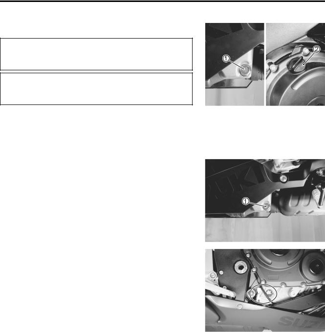
2-12 PERIODIC MAINTENANCE
Oil drain plug: 23 N·m (2.3 kgf-m, 16.5 lb-ft) |
E |
|
L |
|
P |
•Start up the engine and allow it to run forMseveral minutes at idling speed. A
•Turn off the engine andSwait about three minutes, then check the oil level through the inspection window. If the level is
below mark “L”, add oil to “F” level. If the level is above mark “F”, drain oil to “F” level.
F
 L
L

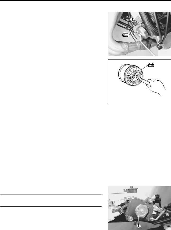
PERIODIC MAINTENANCE 2-13
OIL FILTER REPLACEMENT
• Drain the engine oil as described in the engine oil replacement procedure.
• Remove the oil filter 1 with the special tool.
09915-40610: Oil filter wrench
•Apply engine oil lightly to the gasket of the new oil filter before installation.
•Install the new oil filter. Turn it by hand until you feel that the
oil filter gasket contacts the oil filter mounting surface. Then, tighten the oil filter two full turns (or to specified torque) with the special tool.
NOTE: |
|
|
To properly tighten the oil filter, use the special tool. Never |
After contacting the |
|
tighten the oil filter by hand. |
||
gasket, tighten 2 turns. |
||
Oil filter: 20 N·m (2.0 kgf-m, 14.5 lb-ft) |
||
(20 N·m, 2.0 kgf-m, 14.5 lb-ft) |
|
|
|
|
|
|
|
|
E |
|
• Add new engine oil and check the oil level is as described in |
||||
the engine oil replacement procedure. |
L |
|||
|
|
|
||
NECESSARY AMOUNT OF ENGINE OIL: |
|
|
|
|
Oil change |
: 2.2 L (2.3/1.9 US/Imp qt) |
|
|
|
Oil and filter change |
M |
|
|
|
: 2.5 L (2.6/2.2 US/ImpPqt) |
|
|
||
Engine overhaul |
: 2.9 L (3.1/2.6 US/Imp qt) |
|
|
|
|
|
|
|
|
|
|
|
|
|
S |
|
|
|
|
ONLY USE A GENUINEAUZUKI MOTORCYCLE OIL |
|
|
||
FILTER. Other manufacturer’s oil filters may differ in |
|
|
||
thread specifications (thread diameter and pitch), fil- |
|
|
||
tering performance and durability which may lead to |
|
|
||
engine damage or oil leaks. Also, do not use a genuine |
|
|
||
Suzuki automobile oil filter on this motorcycle. |
|
|
|
|
|
|
|
|
|
EXHAUST CONTROL VALVE
Inspect initially at 1 000 km (600 miles, 2 months) and every 12 000 km (7 500 miles, 24 months) thereafter.
Exhaust control valve actuator is installed in the right-hand side in tail cowl.
Check the exhaust control valve actuator 1 for its movement when the ignition switch is turned ON. If the exhaust valve actuator does not move, check exhaust valve actuator electrical circuit and exhaust valve carbon sticking. Check the exhaust control cable play. ( 6-14)
Loading...