


CLYMER.
SUZUKI
VS700-800 INTRUDER • 1985-1997
SERVICE • REPAIR • MAINTENANCE
QUICK REFERENCE DATA
TIRE INFLATION PRESSURE (COLD)*
Load |
Psi |
Tire Pressure Front |
|
kPa |
|
Rear kPa |
psi |
||||
Solo riding |
28 |
200 |
32 |
225 |
|
Dual riding |
32 |
225 |
36 |
250 |
|
|
|||||
|
|
||||
» Tire inflation pressure for factory equipped tires. Aftermarket tires may |
require different inflation pressure. |
||||
|
|
|
|
||
|
|
RECOMMENDED LUBRICANTS AND FLUIDS |
|
||
Fuel |
|
Regular unleaded |
|
|
|
U.S. and Canada |
|
87 [(R + M)/2 method] or 91 octane or higher |
|||
U.K. and all others |
|
85-95 octane |
|
|
|
Engine oii |
|
SAE 10W-40 API grade SE or SF |
|
||
Capacity |
|
2.4 L (2-5 U.S. qtJ2,1 Imp. qt.) |
|
||
"• |
Change |
|
|
||
Change and filter |
|
2.8 L (3.0 U.S. qt J2.5 Imp. qt.) |
|
||
j> ""At overhaul |
|
3.3 L(3.5 U.S. qt/2.9 Imp. qt.) |
|
||
C$dlanf |
|
Ethylene glycol |
|
|
|
* Capacity at change |
|
1.7 L (1.8 U.S. qtJ1.5 imp. qt.) |
|
||
^tt»al drive oil |
|
SAi 90 hypoid gear oil with |
|
||
«. |
|
|
GL-5 under API classification |
|
|
I ~ Capacity at change |
|
2-2.2 m) (6.8-7.0 U.S. qt J7.4-7.7 Imp. qt.) |
|||
'• f rake fluid |
|
DOT4 |
|
|
|
'ulch hydraulic fluid |
|
DOT 3 or DOT 4 |
|
|
|
-Hmtterf refilling |
|
Distilled water |
|
|
|
5hptnt fork oil capacity (each fork leg) |
SAE 10W |
|
|
||
3 "i |
981 |
|
|
|
|
,^- Right-hand fork |
|
388 ml |
12.1 oz. |
|
|
; |
Left-hand forte |
|
370 ml |
12.5 oz. |
|
;,:if8<M981 |
|
|
|
|
|
;.: u,s. |
|
383 mi |
13.4 oz. |
|
|
r '"" U.K. |
|
394 ml |
13.8 oz. |
|
|
*, /It92-1993 |
|
386 ml |
13.5 oz. |
|
|
'f: W§4-on |
|
412ml |
14.502, |
|
|
J*Brflr*l fork oil leyet dimension |
|
153 mm |
6.02 in. |
|
|
"'t 1985-1989 |
|
|
|||
t990-1991 |
|
|
|
|
|
|
UJS. and U.K. |
|
175 mm |
6.89 in. |
|
• |
Canada |
|
187mm |
7.36 in. |
|
1992-1993 |
|
178 mm |
7.01 in. |
|
|
y U.S., Canada and U.K. |
|
|
|||
' 1994-on |
|
177mm |
6.97 in. |
|
|
J^»rk oH type |
|
SAE 10W fork oil |
|
|
|
Cables and pivot points |
|
Cabie lube or SAE 10W/30 motor oil |
|
||
|
|
|
|
|
|
f; |
|
|
AND TUNE UP TIGHTENING TORQUES |
|
|
MAINTENANCE |
|
|
|||
Item |
|
N.m |
ft.-lb. |
|
|
^•Oil drain plug |
|
18-23 |
13-16.5 |
|
|
/ \telve adjuster locknut |
|
13-16 |
9.5-11.5 |
|
|
Cylinder head side cover bolts |
|
|
|
||
(side opposite spark plug) |
|
21-23 |
15-18 |
|
|
|
|
|
|
|
|
INTRODUCTION
This detailed, comprehensive manual covers the U.S and U.K. models of the Suzuki Intruder 700-800 cc V- twins from 1985-on.
The expert text gives complete information on maintenance, tune-up, repair and overhaul. Hundreds of photos and drawings guide you through every step. The book includes all you will need to know to keep your Suzuki running right. Throughout this book where differences occur among the models, they are clearly identified.
A shop manual is a reference. You want to be able to find information fast. As in all Clymer books, this one is designed with you in mind. All chapters are thumb tabbed. Important items are extensively indexed at the rear of the book. All procedures, tables, photos, etc., in this manual are for the reader who may be working on the bike for the first time or using this manual for the first time. All the most frequently used specifications and capacities are summarized in the Quick Reference Data pages at the front of the book.
Keep the book handy in your tool box. It will help you better understand how your bike runs, lower repair costs and generally improve your satisfaction with the bike.
CHAPTER ONE
GENERAL INFORMATION
This detailed, comprehensive manual covers the U.S. and the U.K. models of the Suzuki Intruder 700-800 cc V-twins from 1985-on. Table 1 lists the chassis numbers (VIN) for models covered in this manual.
Troubleshooting, tune-up, maintenance and repair are not difficult, if you know what tools and equipment to use and what to do. Step-by-step instructions guide you through jobs ranging from simple maintenance to complete engine and suspension overhaul.
This manual can be used by anyone from a first time do-it-yourselfer to a professional mechanic. Detailed drawings and clear photographs give you all the information you need to do the work right.
Some procedures will require the use of special tools. The resourceful mechanic can, in many cases, think of acceptable substitutes for special tools, there is always another way. This can be as simple as using a few pieces of threaded rod, washers and nuts to remove or install a bearing or fabricating a tool from
scrap material. However, using a substitute for a special tool is not recommended as it can be dangerous to and may damage the part. If you find that a tool can be designed and safely made, but will require some type of machine work, you may want to search out a local community college or high school that has a machine shop curriculum. Some shop teachers welcome outside work that can be used as practical shop applications for advanced students.
Table 1 lists model coverage with VIN and frame serial numbers. Metric and U.S. standards are used throughout this manual and U.S. to metric conversion is given in Table 2.
Tables 1-5 are located at the end of this chapter.
MANUAL ORGANIZATION
This chapter provides general information and discusses equipment and tools useful both for preventive maintenance and troubleshooting.

Chapter Two provides methods and suggestions for quick and accurate diagnosis and repair of problems. Troubleshooting procedures discuss typical symptoms and logical methods to pinpoint the trouble.
Chapter Three explains all periodic lubrication and routine maintenance necessary to keep your Suzuki operating well and competitive. Chapter Three also includes recommended tune-up procedures, eliminating the need to constantly consult other chapters on the various assemblies.
Subsequent chapters describe specific systems such as the engine top end, engine bottom end, clutch, transmission, fuel, exhaust, electrical, cooling, suspension, drive train, steering and brakes. Each chapter provides disassembly, repair and assembly procedures in simple step-by-step form. If a repair is impractical for a home mechanic, it is so indicated. It is usually faster and less expensive to take such repairs to a Suzuki dealer or competent repair shop. Specifications concerning a particular system are included at the end of the appropriate chapter.
NOTES, CAUTIONS
AND WARNINGS
The terms NOTE, CAUTION and WARNING have specific meanings in this manual. A NOTE provides additional information to make a step or procedure easier or clearer. Disregarding a NOTE could cause inconvenience, but would not cause damage or personal injury.
A CAUTION emphasizes an area where equipment damage could occur. Disregarding a CAUTION could cause permanent mechanical damage; however, personal injury is unlikely.
A WARNING emphasizes an area where personal injury or even death could result from negligence. Mechanical damage may also occur. WARNINGS are to be taken seriously. In some cases, serious injury and death has resulted from disregarding similar warnings.
SAFETY FIRST
Professional mechanics can work for years and never sustain a serious injury. If you observe a few rules of common sense and safety, you can enjoy many safe hours servicing your own machine. If you
ignore these rules you can hurt yourself or damage the equipment.
1.Never use gasoline as a cleaning solvent.
2.Never smoke or use a torch in the vicinity of flammable liquids, such as cleaning solvent, in open containers.
3.If welding or brazing is required on the machine, remove the fuel tank and rear shock to a safe dis tance, at least 50 feet away.
4.Use the proper sized wrenches to avoid damage to fasteners and injury to yourself.
5.When loosening a tight or stuck nut, be guided by what would happen if the wrench should slip. Be careful; protect yourself accordingly.
6.When replacing a fastener, make sure to use one with the same measurements and strength as the old one. Incorrect or mismatched fasteners can result in

damage to the bike and possible personal injury. Beware of fastener kits that are filled with cheap and poorly made nuts, bolts, washers and cotter pins. Refer to Fasteners in this chapter for additional information.
7.Keep all hand and power tools in good condition. Wipe greasy and oily tools after using them. They are difficult to hold and can cause injury. Replace or repair worn or damaged tools.
8.Keep your work area clean and uncluttered.
9.Wear safety goggles during all operations involv ing drilling, grinding, the use of a cold chisel or anytime you feel unsure about the safety of your eyes. Safety goggles should also be worn anytime solvent and compressed air is used to clean a part.
10.Keep an approved fire extinguisher nearby (Fig ure 1). Be sure it is rated for gasoline (Class B) and electrical (Class C) fires.
11.When drying bearings or other rotating pans with compressed air, never allow the air jet to rotate the bearing or part. The air jet is capable of rotating them at speeds far in excess of those for which they were designed. The bearing or rotating part is very likely to disintegrate and cause serious injury and
damage. To prevent bearing damage when using compressed air, hold the inner bearing race by hand
(Figure 2).
SERVICE HINTS
Most of the service procedures covered are straightforward and can be performed by anyone reasonably handy with tools. It is suggested, however, that you consider your own capabilities carefully before attempting any operation involving major disassembly of the engine or transmission.
Take your time and do the job right. Do not forget that a newly rebuilt engine must be broken-in the same way as a new one. Keep the rpm within the limits given in your owner's manual when you get back on the road or out in the dirt.
1."Front," as used in this manual, refers to the front of the bike; the front of any component is the end closest to the front of the bike. The "left-" and "righthand" sides refer to the position of the parts as viewed by a rider sitting on the seat facing forward. For exam ple, the throttle control is on the right-hand side. These rules are simple, but confusion can cause a major inconvenience during service.
2.Whenever servicing the engine or clutch, or when removing a suspension component, the bike should be secured in a safe manner.
WARNING
Never disconnect the positive (+) battery cable unless the negative (-) cable has first been disconnected. Disconnecting the positive cable while the negative cable is still connected may cause a spark. This could ignite hydrogen gas given off by the battery, causing an explosion.
3.Disconnect the negative battery cable (Figure 3) when working on or near the electrical, clutch, or starter systems and before disconnecting any elec trical wires. On most batteries, the negative terminal will be marked with a minus (-) sign and the positive terminal with a plus (+) sign.
4.Tag all similar internal parts for location and mark all mating parts for position (A, Figure 4). Record number and thickness of any shims as they are removed. Small parts such as bolts can be iden tified by placing them in plastic sandwich bags (B, Figure 4). Seal and label them with masking tape.

5.Place parts from a specific are of the engine (e.g. cylinder head, cylinder, clutch, shift mechanism, etc.) into plastic boxes (C, Figure 4) to keep them separated.
6.When disassembling transmission shaft assem blies, use an egg flat (the type that restaurants get their eggs in) (D, Figure 4) and set the parts from the shaft in one of the depressions in the same order in which is was removed.
NOTE
Some of the procedures or service specifications listed in this manual may not be applicable if your Suzuki has been modified or if it has been equipped with non-stock equipment. When modifying or installing non-stock equipment, file all printed instruction or technical information regarding the new equipment in a folder or notebook for future reference. If your Suzuki was purchased second hand, the previous owner may have installed non-stock parts. If necessary, consult with your dealer or the accessory manufacturer on components that may affect tuning or repair procedures.
1. Wiring should be tagged with masking tape and marked as each wire is removed. Again, do not rely on memory alone.
8.Finished surfaces should be protected from physical damage or corrosion. Keep gasoline and brake fluid off painted surfaces.
9.Use penetrating oil on frozen or tight bolts, then strike the bolt head a few times with a hammer and punch (use a screwdriver on screws). Avoid the use of heat where possible, as it can warp, melt or affect the temper of parts. Heat also ruins finishes, espe cially paint and plastics.
10.No parts removed or installed (other than bush ings and bearings) in the procedures given in this manual should require unusual force during disas sembly or assembly. If a part is difficult to remove or install, find out why before proceeding.
11.Cover all openings after removing parts or com ponents to prevent dirt, small tools, etc. from falling in.
12.Read each procedure completely while looking at the actual parts before starting a job. Make sure you thoroughly understand what is to be done and then carefully follow the procedure, step-by-step.
13.Recommendations are occasionally made to re fer service or maintenance to a Suzuki dealer or a specialist in a particular field. In these cases, the work will be done more quickly and economically than if you performed the job yourself.
14.In procedural steps, the term "replace" means to discard a defective part and replace it with a new or exchange unit. "Overhaul" means to remove, disas semble, inspect, measure, repair or replace defective parts, reassemble and install major systems or parts.
15.Some operations require the use of a hydraulic press. Unless you have a press, it would be wiser to have these operations performed by a shop equipped for such work, rather than to try to do the job yourself with makeshift equipment that may damage your machine.
16.Repairs go much faster and easier if your ma chine is clean before you begin work. There are many special cleaners on the market, like Simple Green or Bel-Ray Degreaser, for washing the engine and related parts. Follow the manufacturer's direc tions on the container for the best results. Clean all oily or greasy parts with cleaning solvent as you remove them.
WARNING
Never use gasoline as a cleaning agent. It presents an extreme fire hazard. Be sure to work in a well-ventilated area when using cleaning solvent. Keep afire extinguisher, rated for gasoline fires, handy in any case.
CAUTION
If you use a car wash to clean your bike, don't direct the high pressure water hose at steering bearings, carburetor hoses,
suspension linkage components, wheel bearings and electrical components. The water will flush grease out of the bearings or damage the seals.
17.Much of the labor charges for repairs made by dealers are for the time involved during in the re moval, disassembly, assembly, and reinstallation of other parts in order to reach the defective part. It is frequently possible to perform the preliminary op erations yourself and then take the defective unit to the dealer for repair at considerable savings.
18.If special tools are required, make arrangements to get them before you start. It is frustrating and time-consuming to get partly into a job and then be unable to complete it.
19.Make diagrams (or take a Polaroid picture) wherever similar-appearing parts are found. For in stance, crankcase bolts are often not the same length. You may think you can remember where everything came from—but mistakes are costly. There is also the possibility that you may be sidetracked and not return to work for days or even weeks—in which the time carefully laid out parts may have become dis turbed.
20.When assembling parts, be sure all shims and washers are replaced exactly as they came out.
21.Whenever a rotating part butts against a station ary part, look for a shim or washer. Use new gaskets if there is any doubt about the condition of the old ones. A thin coat of oil on non-pressure type gaskets may help them seal more effectively.
22.High spots may be sanded off a piston with sandpaper, but fine emery cloth and oil will do a much more professional job.
23.Carbon can be removed from the head, the piston crowns and the exhaust ports with a dull screwdriver. Do not scratch machined surfaces. Wipe off the surface with a clean cloth when fin ished.
24.A baby bottle makes a good measuring device for adding oil to the front forks. Get one that is graduated in fluid ounces and cubic centimeters. After it has been used for this purpose, do not let a small child drink out of it as there will always be an oil residue in it.
25.If it is necessary to make a clutch cover or ignition cover gasket and you do not have a suitable old gasket to use as a guide, you can use the outline of the cover and gasket material to make a new gasket. Apply engine oil to the cover gasket surface. Then place the cover on the new gasket material and apply pressure with your hands. The oil will leave a very accurate outline on the gasket material that can be cut around.
CAUTION
When purchasing gasket material to make a gasket, measure the thickness of the old gasket and purchase gasket material with the same approximate thickness.
26.Heavy grease can be used to hold small parts in place if they tend to fall out during assembly. How ever, keep grease and oil away from electrical and brake components.
27.The carburetor is best cleaned by disassembling it and soaking the parts in a commercial cleaning solvent. Never soak gaskets and rubber parts in these cleaners. Never use wire to clean out jets and air passages. They are easily damaged. Use compressed air to blow out the carburetor only if the float has been removed first.
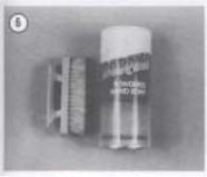
28.There are many items available that can be used on your hands before and after working on your bike. A little preparation prior to getting "all greased up" will help when cleaning up later. Before starting out, work Vaseline, soap or a product such as Invisible Glove (Figure 5) onto your forearms, into your hands and under your fingernails and cuticles. This will make cleanup a lot easier. For cleanup, use a waterless hand soap such as Sta-Lube and then finish up with powdered Boraxo and a fingernail brush
(Figure 6).
PARTS REPLACEMENT
When you order parts from the dealer or other parts distributor, always order by frame and engine serial numbers. Refer to Table 1. Compare new parts to old before purchasing them. If they are not alike, have the parts manager explain the difference to you.
TORQUE SPECIFICATIONS
Torque specifications throughout this manual are given in Newton-meters (N.m) and foot-pounds (ft.- lb.).
Existing torque wrenches calibrated in meter kilograms can be used by performing a simple conversion. All you have to do is move the decimal point one place to the right; for example, 3.5 mkg = 35 N.m. This conversion is accurate enough for mechanical work even though the exact mathematical conversion is 3.5 mkg = 34.3 N-m.
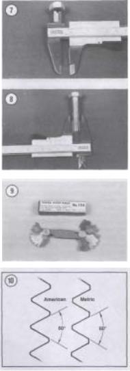
Refer to Table 3 for general torque specifications for various size screws, bolts and nuts that may not be listed in the respective chapters. To use the table, first determine the size of the bolt or nut. Use a vernier caliper and measure the inside dimension of the threads of the nut (Figure 7) and across the threads for a bolt (Figure 8).
FASTENERS
The materials and designs of the various fasteners used on your Suzuki are not arrived at by chance or accident. Fastener design determines the type of tool required to work the fastener. Fastener material is carefully selected to decrease the possibility of physical failure.
Nuts, bolts and screws are manufactured in a wide range of thread patterns. To join a nut and bolt, the diameter of the bolt and the diameter of the hole in the nut must be the same. It is just as important that the threads on both be properly matched.
The best way to tell if the threads on 2 fasteners are matched is to turn the nut on the bolt (or the bolt into the threaded hole in a piece of equipment) with fingers only. Be sure both pieces are clean. If much force is required, check the thread condition on each fastener. If the thread condition is good but the fasteners jam, the threads are not compatible. A thread pitch gauge (Figure 9) can also be used to determine pitch. Suzuki motorcycles are manufac-
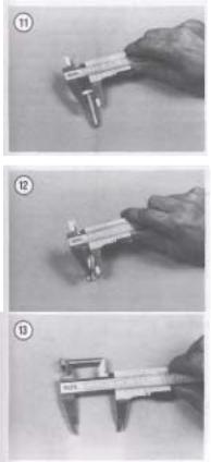
tured with ISO (International Organization for Standardization) metric fasteners. The threads are cut differently than that of American fasteners (Figure 10).
Most threads are cut so that the fastener must be turned clockwise to tighten it. These are called righthand threads. Some fasteners have left-hand threads; they must be turned counterclockwise to be light-
ened. Left-hand threads are used in locations where normal rotation of the equipment would tend to loosen a right-hand threaded fastener.
ISO Metric Screw Threads
ISO (International Organization for Standardization) metric threads come in 3 standard thread sizes: coarse, fine and constant pitch. The ISO coarse pitch is used for most all common fastener applications. The fine pitch thread is used on certain precision tools and instruments. The constant pitch thread is used mainly on machine pans and not for fasteners. The constant pitch thread, however, is used on all metric thread spark plugs.
ISO metric threads are specified by the capital letter M followed by the diameter in millimeters and the pitch (or the distance between each thread) in millimeters separated by the sign x. For example a M8 x 1.25 bolt is one that has a diameter of 8 millimeters with a distance of 1.25 millimeters between each thread. The measurement across 2 flats on the head of the bolt (Figure 11) indicates the proper wrench size to be used. Figure 12 shows how to determine bolt diameter.
NOTE
When purchasing a bolt from a dealer or parts store, it is important to know how to specify bolt length. The correct way to measure bolt length is by measuring the length starting from underneath the bolt head to the end of the bolt (Figure 13). Always measure bolt length in this manner to avoid purchasing bolts that are too long or too short.
Machine Screws
There are many different types of machine screws. Figure 14 shows a number of screw heads requiring different types of turning tools. Heads are also designed to protrude above the metal (round) or to be slightly recessed in the metal (flat). See Figure 15.
Bolts
Commonly called bolts, the technical name for these fasteners is cap screws. Metric bolts are described by the diameter and pitch (or the distance
between each thread). For example a M8 x 1.25 bolt is one that has a diameter of 8 millimeters and a distance of 1.25 millimeters between each thread. The measurement across 2 flats on the head of the bolt (Figure 11) indicates the proper wrench size to be used. Use a vernier caliper and measure across the threads (Figure 12) to determine the bolt diameter and to measure the length (Figure 13).
Nuts
Nuts are manufactured in a variety of types and sizes. Most are hexagonal (6-sided) and fit on bolts, screws and studs with the same diameter and pitch.
Figure 16 shows several types of nuts. The common nut is generally used with a lockwasher. Self-locking nuts have a nylon insert which prevents the nut from loosening; no lockwasher is required. Wing nuts are designed for fast removal by hand. Wing nuts are used for convenience in non-critical locations.
To indicate the size of a metric nut, manufacturers specify the diameter of the opening and the thread pitch. This is similar to bolt specifications, but without the length dimension. The measurement across 2 flats on the nut indicates the proper wrench size to be used (Figure 17).
Self-locking Fasteners
Several types of bolts, screws and nuts incorporate a system that develops an interference between the bolt, screw, nut or tapped hole threads. Interference is achieved in various ways: by distorting threads, coating threads with dry adhesive or nylon, distorting the top of an all-metal nut, using a nylon insert in the center or at the top of a nut, etc.
Self-locking fasteners offer greater holding strength and better vibration resistance. Some prevailing torque fasteners can be reused if in good condition. Others, like the nylon insert nut, form an initial locking condition when the nut is first in-
OPENINGS FOR TURNING TOOLS
MACHINE SCREWS

stalled; the nylon forms closely to the bolt thread 1 pattern, thus reducing any tendency for the nut to I loosen. When the nut is removed, the locking efficiency is greatly reduced. For greatest safety, it is recommended that you install new self-locking fasteners whenever they are removed.
Washers
There are 2 basic types of washers: flat washers and lockwashers. Flat washers are simple discs with a hole to fit a screw or bolt. Lockwashers are designed to prevent a fastener from working loose due to vibration, expansion and contraction. Figure 18 shows several types of washers. Washers are also used in the following functions:
a.As spacers.
b.To prevent galling or damage of the equipment by the fastener.
c.To help distribute fastener load during torquing.
d.As seals.
Note that flat washers are often used between a lockwasher and a fastener to provide a smooth bearing surface. This allows the fastener to be turned easily with a tool.
Cotter Pins
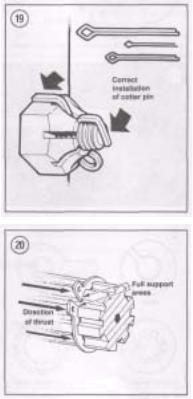
Cotter pins (Figure 19) are used to secure fasteners in a special location. The threaded stud, bolt or axle must have a hole in it. Its nut or nut lock piece has castellations around its upper edge into which the cotter pin fits to keep it from loosening. When properly installed, a cotter pin is a positive locking device.
The first step in properly installing a cotter pin is to purchase one that will fit snugly when inserted through the nut and the mating thread part. This should not be a problem when purchasing cotter pins through a Suzuki dealer; you can order them by their respective part numbers. However, when you purchase them at a hardware or automotive store, keep this in mind. The cotter pin should not be so tight that you have to drive it in and out, but you do not want it so loose that it can move or float after it is installed.
Before installing a cotter pin, tighten the nut to the recommended torque specification. If the castellations in the nut do not line up with the hole in the
bolt or axle, tighten the nut until alignment is achieved. Do not loosen the nut to make alignmentInsert a new cotter pin through the nut and hole, then tap the head lightly to seat it. Bend one arm over the flat on the nut and the other against the top of the axle or bolt. Cut the arms to a suitable length to prevent them from snagging on clothing, or worse, your hands, arms or legs; the exposed arms will cut flesh easily. When the cotter pin is bent and its arms cut to length, it should be tight. If you can wiggle the cotter pin, it is improperly installed.
Cotter pins should not be reused as their ends may break and allow the cotter pin to fall out and perhaps the fastener to unscrew itself.
Circlips
Circlips can be internal or external design. They are used to retain items on shafts (external type) or within bores (internal type). In some applications, circlips of varying thicknesses are used to control the end play of parts assemblies. These are often called selective circlips. Circlips should be replaced during installation, as removal weakens and deforms them.
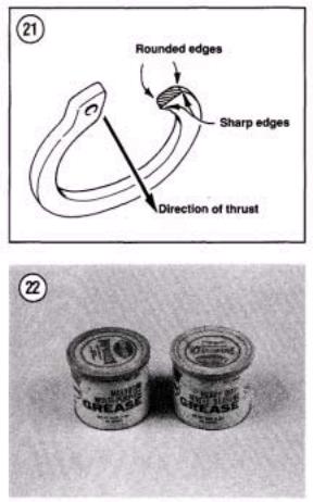
Two basic styles of circlips are available: machined and stamped circlips. Machined circlips (Figure 20) can be installed in either direction (shaft or housing) because both faces are machined, thus creating two sharp edges. Stamped circlips (Figure 21) are manufactured with one sharp edge and one rounded edge. When installing stamped circlips in a thrust situation (transmission shafts, fork tubes, etc.), the sharp edge must face away from the part producing the thrust. When installing circlips, observe the following:
a.Compress or expand circlips only enough to install them.
b.After the circlip is installed, make sure it is completely seated in its groove.
Transmission circlips become worn with use and increase side play. For this reason, always use new circlips when ever a transmission is to be reassembled.
LUBRICANTS
Periodic lubrication assures long life for any type of equipment. The type of lubricant used is just as important as the lubrication service itself, although in an emergency the wrong type of lubricant is better
than none at all. The following paragraphs describe the types of lubricants most often used on motorcycle equipment. Be sure to follow the manufacturer's recommendations for lubricant types.
Generally, all liquid lubricants are called "oil." They may be mineral-based (including petroleum bases), natural-based (vegetable and animal bases), synthetic-based or emulsions (mixtures). "Grease" is an oil to which a thickening base has been added so that the end product is semi-solid. Grease is often classified by the type of thickener added; lithium soap is commonly used.
Engine Oil
Four-cycle oil for motorcycle and automotive engines is graded by the American Petroleum Institute (API) and the Society of Automotive Engineers (SAE) in several categories. Oil containers display these ratings on the top or label.
API oil grade is indicated by letters; oils for gasoline engines are identified by an "S". Suzuki models described in this manual require SE or SF graded oil.
Viscosity is an indication of the oil's thickness. The SAE uses numbers to indicate viscosity; thin oils have low numbers while thick oils have high numbers. A "W" after the number indicates that the viscosity testing was done at low temperature to simulate cold-weather operation. Engine oils fall into the 5 to 50 range.
Multi-grade oils (for example 10W-40) are less viscous (thinner) at low temperatures and more viscous (thicker) at high temperatures. This allows the
oil to perform efficiently across a wide range of | engine operating conditions. The lower the number, the better the engine will start in cold climates. Higher numbers are usually recommended for engine running in hot weather conditions.
Grease
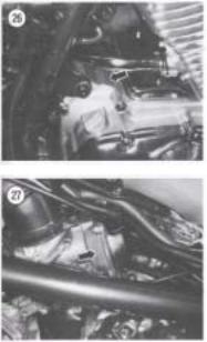
Greases are graded by the National Lubricating Grease Institute (NLGI). Greases are graded by number according to the consistency of the grease; these range from No. 000 to No. 6, with No. 6 being the most solid. A typical multipurpose grease is NLGI No. 2. For specific applications, equipment manufacturers may require grease with an additive such as molybdenum disulfide (MOS2) (Figure 22).
RTV GASKET SEALANT
Room temperature vulcanizing (RTV) sealant is used on some pre-formed gaskets and to seal some components. RTV is a silicone gel supplied in tubes and can be purchased in a number of different colors.
Moisture in the air causes RTV to cure. Always place the cap on the tube as soon as possible when using RTV sealants?RTV has a shelf life of one year and will not cure properly when the shelf life has expired. Check the expiration date on RTV tubes before using and keep partially used tubes tightly sealed.
Applying RTV Sealant
Clean all gasket residue from mating surfaces. Surfaces should be clean and free of oil and dirt. Remove all RTV gasket material from blind attaching holes, as it can cause a "hydraulic" effect and affect bolt torque.
Apply RTV sealant in a continuous bead. Circle all mounting holes unless otherwise specified. Torque mating parts within 10 minutes after application.
THREADLOCK
A chemical such as "Loctite." A locking compound will lock fasteners against vibration loosening and seal against leaks. Loctite 242 (blue) and 271

(red) are recommended for many threadlock requirements described in this manual.
Loctite 242 (blue) is a medium strength threadlock and component disassembly can be performed with normal hand tools. Loctite 271 (red) is a high strength threadlock and heat or special tools, such as a press or puller, may be required for component disassembly.
Applying Threadlock
Surfaces should be clean and free of oil, grease, dirt and other residue; clean threads with an aerosol electrical contact cleaner before applying the Loctite. When applying Loctite, use a small amount. If too much is used, it may work its way into parts not meant to be stuck together.
GASKET REMOVER
Stubborn gaskets can present a problem during engine service as they can take a long time to remove. Consequently, there is the added problem of secondary damage occurring to the gasket mating surfaces from the incorrect use of gasket scraping tools. To quickly and safely remove stubborn gaskets, use a spray gasket remover. Spray gasket remover can be purchased through automotive parts houses. Follow the manufacturer's directions for use.
EXPENDABLE SUPPLIES
Certain expendable supplies are required during maintenance and repair work. These include grease, oil. gasket cement, wiping rags and cleaning solvent. Ask your dealer for the special locking compounds, silicone lubricants and other products (Figure 23) which make bike maintenance simpler and easier. Cleaning solvent or kerosene is available at some service stations, paint or hardware stores.
WARNING
Having a stack of clean shop rags on hand is important when performing engine and suspension service work. However, to prevent the possibility of fire damage from spontaneous combustion from a pile of solvent soaked rags, store
them in a lid sealed metal container until they can be washed or discarded.
NOTE
To avoid absorbing solvent and other chemicals into your skin while cleaning parts, wear a pair of petroleum-resistant rubber gloves. These can be purchased through industrial supply houses or wellequipped hardware stores.
PARTS REPLACEMENT
Suzuki makes frequent changes during a model year, some minor, some relatively major. When you order parts from the dealer or other parts distributor, always order by frame and engine numbers. The frame number serial number is stamped on the righthand side of the steering head (Figure 24). The vehicle identification number (VIN) plate is attached to the left-hand side of the frame down tube (Figure 25). The engine number is stamped on a raised pad on the right-hand side of the crankcase (Figure 26) behind the starter motor cover. The carburetor number (Figure 27) is on the side of the carburetor body below the top cover.
Write the numbers down and carry them with you. Compare new parts to old before purchasing them. If they are not alike, have the parts manager explain the difference to you. Table 1 lists engine and frame serial numbers for the models covered in this manual.
NOTE
If your Suzuki was purchased secondhand and you are not sure of its model year, use the bike's VINandframe serial numbers and the information listed in Table 1. Read your bike's serial number. Then compare the numbers listed in Table 1. If your bike's serial number is listed in Table 1, cross-reference the number with the adjacent model number and year.
BASIC HAND TOOLS
Many of the procedures in this manual can be carried out with simple hand tools and test equipment familiar to the average home mechanic. Keep your tools clean and in a tool box. Keep them organized with the sockets and related drives together, the open-end combination wrenches together, etc. After using a tool, wipe off dirt and grease with a clean cloth and return the tool to its correct place.
Top quality tools are essential; they are also more economical in the long run. If you are now starting to build your tool collection, stay away from the "advertised specials" featured at some parts houses, discount stores and chain drug stores. These are usually a poor grade tool that can be sold cheaply and that is exactly what they are—cheap. They are usually made of inferior material, and are thick, heavy and clumsy. Their rough finish makes them difficult to clean and they usually don't last very long. If it is ever your misfortune to use such tools, you will probably find out that the wrenches do not fit the heads of bolts and nuts correctly and damage the fastener.
Quality tools are made of alloy steel and are heat treated for greater strength. They are lighter and better balanced than cheap ones. Their surface is smooth, making them a pleasure to work with and easy to clean. The initial cost of good quality tools may be more but they are cheaper in the long run. Don't try to buy everything in all sizes in the beginning; do it a little at a time until you have the necessary tools.
The following tools are required to perform virtually any repair job on a bike. Each tool is described and the recommended size given for starting a tool collection. Table 4 includes the tools that should be on hand for simple home repairs and/or major over-
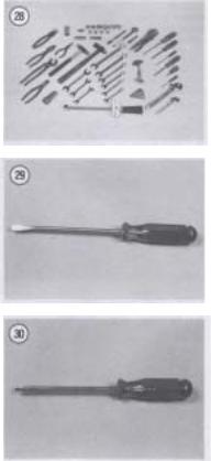
haul as shown in Figure 28. Additional tools and some duplicates may be added as you become more familiar with the bike. Almost all motorcycles and vehicles (with the exception of the U.S. built Harley Davidson and some English motorcycles) use metric size bolts and nuts. If you are starting your collection now, buy metric sizes.
Screwdrivers
The screwdriver is a very basic tool, but if used improperly it will do more damage than good. The slot on a screw has a definite dimension and shape. A screwdriver must be selected to conform with that shape. Use a small screwdriver for small screws and a large one for large screws or the screw head will be damaged.
Two basic types of screwdrivers are required: common (flat-blade) screwdrivers (Figure 29) and Phillips screwdrivers (Figure 30).
Note the following when selecting and using screwdrivers:
a.The screwdriver must always fit the screw head. If the screwdriver blade is too small for the screw slot, damage may occur to the screw slot and screwdriver. If the blade is too large, it cannot engage the slot properly and will result in damage to the screw head.
b.Standard screwdrivers are identified by the length of their blade. A 6-inch screwdriver has ablade six inches long. The width of the screw driver blade will vary, so make sure that the blade engages the screw slot the complete width of the screw.
c.Phillips screwdrivers are sized according to their point size. They are numbered one, two, three and four. The degree of taper determines the point size; the No. 1 Phillips screwdriver will be the most pointed. The points become more blunt as their number increases.
NOTE
You should also be aware of another screwdriver similar to the Phillips, and that is the Reed and Prince tip. Like the Phillips, the Reed and Prince screwdriver tip forms an "X" but with one major exception, the Reed and Prince tip has a much more pointed tip. The Reed and Prince screwdriver should never be used on Phillips screws and
vise versa. Intermixing these screwdrivers will cause damage to the screw and screwdriver. If you have both types in your tool box and they are similar in appearance, you may want to identify them by painting the screwdriver shank underneath the handle.
d.When selecting screwdrivers, note that you can apply more power with less effort with a longer

screwdriver than with a short one. Of course, there will be situations where only a short handle screwdriver can be used. Keep this in mind though, when having to remove tight screws.
e. Because the working end of a screwdriver receives quite a bit of abuse, you should purchase screwdrivers with hardened-tips. The extra money will be well spent. Screwdrivers are available in sets which often include an assortment of common and Phillips blades. If you buy them individually, buy at least the following:
a.Common screwdriver—5/16 x 6 in. blade.
b.Common screwdriver—3/8 x 12 in. blade.
c.Phillips screwdriver—size 2 tip, 6 in. blade.
d.Phillips screwdriver—size 3 tip, 6 and 8 in. blade.
Use screwdrivers only for driving screws. Never use a screwdriver for prying or chiseling metal. Do not try to remove a Phillips, Torx or Allen head screw with a standard screwdriver (unless the screw has a combination head that will accept either type); you can damage the head so that the proper tool will be unable to remove it.
Keep screwdrivers in the proper condition and they will last longer and perform better. Always keep the tip of a standard screwdriver in good condition. Figure 31 shows how to grind the tip to the proper shape if it becomes damaged. Note the symmetrical sides of the tip.
Pliers
Pliers come in a wide range of types and sizes. Pliers are useful for cutting, bending and crimping. They should never be used to cut hardened objects
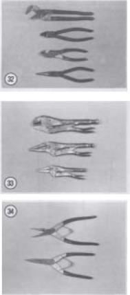
or to turn bolts or nuts. Figure 32 shows several pliers useful in repairing your Suzuki.
Each type of pliers has a specialized function. Slip-joint pliers are general purpose pliers and are used mainly for holding things and for bending. Needlenose pliers are used to hold or bend small objects. Water pump pliers can be adjusted to hold various sizes of objects; the jaws remain parallel to grip around objects such as pipe or tubing. There are many more types of pliers.
CAUTION
Pliers should not be used for loosening or tightening nuts or bolts. The pliers' sharp teeth will grind off the nut or bolt corners and damage it.
CAUTION
If slip-joint or water pump pliers are going to be used to hold an object with a finished surface, wrap the object with tape or cardboard for protection.
Vise-grip Pliers
Vise-grip pliers (Figure 33) are used to hold objects very tightly while another task is performed on the object. While vise-grip pliers work well, caution should be followed with their use. Because vise-grip pliers exert more force than regular pliers, their sharp jaws can permanently scar the object. In addition, when vise-grip pliers are locked into position, they can crush or deform thin wall material.
Vise-grip pliers are available in many types for more specific tasks.
Circlip (Snap Ring) Pliers
Circlip pliers (Figure 34) are special in that they are only used to remove circlips from shafts or within engine or suspension housings. When purchasing circlip pliers, there are two kinds to distinguish from. External pliers (spreading) are used to remove circlips that fit on the outside of a shaft. Internal pliers (squeezing) are used to remove circlips which fit inside a gear or housing.
WARNING
Because circlips can sometimes slip and "fly off" during removal and installation, always wear safety glasses.
Box-end, Open-end and Combination Wrenches
Box-end, open-end and combination wrenches are available in sets or separately in a variety of sizes. On openand box-end wrenches, the number stamped near the end refers to the distance between 2 parallel flats on the hex head bolt or nut. On combination wrenches, the number is stamped near the center.
Box-end wrenches require clear overhead access to the fastener but can work well in situations where the fastener head is close to another part. They grip on all six edges of a fastener for a very secure grip. They are available in either 6-point or 12-point. The 6-point gives superior holding power and durability but requires a greater swinging radius. The 12-point works better in situations with limited swinging radius.
Open-end wrenches are speedy and work best in areas with limited overhead access. Their wide flat
jaws make them unstable for situations where the bolt or nut is sunken in a well or close to the edge of a casting. These wrenches grip only two flats of a fastener so if either the fastener head or the wrench jaws are worn, the wrench may slip off.
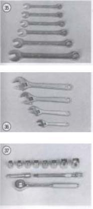
Combination wrenches (Figure 35) have openend on one side and box-end on the other with both ends being the same size. These wrenches are favored by professionals because of their versatility.
Adjustable (Crescent) Wrenches
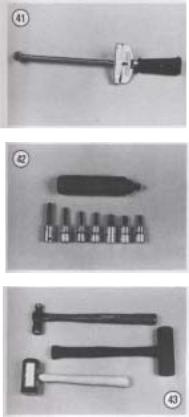
An adjustable wrench (sometimes called crescent wrench) can be adjusted to fit nearly any nut or bolt head which has clear access around its entire perimeter. Adjustable wrenches (Figure 36) are best used as a backup wrench to keep a large nut or bolt from turning while the other end is being loosened or tightened with a proper wrench.
Adjustable wrenches have only two gripping surfaces which make them more subject to slipping off the fastener, damaging the part and possibly injuring your hand. The fact that one jaw is adjustable only aggravates this shortcoming.
These wrenches are directional; the solid jaw must be the one transmitting the force. If you use the adjustable jaw to transmit the force, it will loosen and possibly slip off.
Adjustable wrenches come in all sizes but something in the 6 to 8 in. range is recommended as an all-purpose wrench.
Socket Wrenches
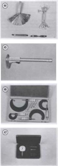
This type is undoubtedly the fastest, safest and most convenient to use. Sockets which attach to a ratchet handle (Figure 37) are available with 6-point or 12-point openings and 1/4,3/8 and 3/4 in. drives. The drive size indicates the size of the square hole which mates with the ratchet handle (Figure 38).
Allen Wrenches
Allen wrenches (Figure 39) are available in sets or separately in a variety of sizes. These sets come in SAE and metric size, so be sure to buy a metric set. Allen bolts are sometimes called socket bolts. Sometimes the bolts are difficult to reach and it is suggested that a variety of Allen wrenches be pur-
chases (e.g. socket driven, T-handle and extension type) as shown in Figure 40.
Torque Wrench
A torque wrench is used with a socket to measure how tightly a nut or bolt is installed. They come in a wide price range and with either 3/8 or 1/2 in. square drive (Figure 41). The drive size indicates the size of the square drive which mates with the socket. Purchase one that measures 0-280 N-m (0- 200 ft.-lb.).
Impact Driver
This tool might have been designed with the bike in mind. This tool makes removal of fasteners easy and minimizes damage to bolts and screw slots. Impact drivers and interchangeable bits (Figure 42) are available at most large hardware, motorcycle and auto parts stores. Don't purchase a cheap one as they do not work as well and require more force (the "use a larger hammer" syndrome) than a moderately priced one. Sockets can also be used with a hand impact driver. However, make sure that the socket is designed for use with an impact driver or air tool. Do not use regular hand sockets, as they may shatter during use.
Hammers
The correct hammer (Figure 43) is necessary for repairs. A hammer with a face (or head) of rubber or plastic or the soft-faced type that is filled with buckshot is sometimes necessary in engine tear downs. Never use a metal-faced hammer on engine or suspension parts, as severe damage will result in most cases. Ball-peen or machinist's hammers will be required when striking another tool, such as a punch or impact driver. When striking a hammer against a punch, cold chisel or similar tool, the face of the hammer should be at least 1/2 in. larger than the head of the tool. When it is necessary to strike hard against a steel part without damaging it, a brass hammer should be used. A brass hammer can be used because brass will give when striking a harder object. When using hammers, note the following: a. Always wear safety glasses when using a hammer.
b.Inspect hammers for damaged or broken parts. Repair or replace the hammer as required. Do not use a hammer with a taped handle.
c.Always wipe oil or grease off of the hammer before using it.
d.The head of the hammer should always strike the object squarely. Do not use the side of the hammer or the handle to strike an object.
e. Always use the correct hammer for the job.
Tap and Die Set
Acomplete tap and die set is a relatively expensive tool. But when you need a tap or die to clean up a damaged thread, there is really no substitute. Be sure to purchase one for metric threads when working on your Suzuki.
Tire Levers
When changing tires, use a good set of tire levers. Never use a screwdriver in place of a tire lever; refer to Chapter Ten for tire changing procedures using these tools. Before using the tire levers, check the working ends of the tool and remove any burrs. Don't use a tire lever for prying anything but tires. For better leverage when changing tires on your Suzuki, you may want to invest in a set of 16 in. long tire irons. These can be ordered through your dealer.
Drivers and Pullers
These tools are used to remove and install oil seals, bushings, bearings and gears. These will be called out during service procedures in later chapters as required.
PRECISION MEASURING TOOLS
Measurement is an important part of motorcycle service. When performing many of the service procedures in this manual, you will be required to make a number of measurements. These include basic checks such as valve clearance, engine compression and spark plug gap. As you get deeper into engine disassembly and service, measurements will be required to determine the size and condition of the piston and cylinder bore, valve and guide wear, camshaft wear, crankshaft runout and so on. When making these measurements, the degree of accuracy will dictate which tool is required. Precision measuring tools are expensive. If this is your first experience at engine or suspension service, it may be more worthwhile to have the checks made at a Suzuki dealer or machine shop. However, as your skills and enthusiasm increase for doing your own service work, you may want to begin purchasing some of these specialized tools. The following is a description of the measuring tools required during engine and suspension overhaul.
Feeler Gauge
Feeler gauges come in assorted sets and types (Figure 44). The feeler gauge is made of either a piece of a flat or round hardened steel of a specified thickness. Wire gauges are frequently recommended to measure spark plug gap. Flat gauges are used for
all other measurements. Feeler gauges are also designed for specialized uses, such as for measuring valve clearances. On these gauges, the gauge end is usually small enough and angled so as to make checking valve clearances easier.
Vernier Caliper
This tool (Figure 45) is invaluable when reading inside, outside and depth measurements to within close precision. It can be used to measure clutch spring length and the thickness of clutch plates, shims and thrust washers.
Outside Micrometers
One of the most reliable tools used for precision measurement is the outside micrometer (Figure 46). Outside micrometers will be required to measure valve shim thickness, piston diameter and valve stem diameter. Outside micrometers are also used with other tools to measure the cylinder bore and the valve guide inside diameters. Micrometers can be purchased individually or as a set.
Dial Indicator
Dial indicators (Figure 47) are precision tools used to check dimension variations on machined parts such as transmission shafts and axles and to check crankshaft and axle shaft end play. Dial indicators are available with various dial types for different measuring requirements.
Cylinder Bore Gauge
The cylinder bore gauge is a very specialized precision tool. The gauge set shown in Figure 48 is comprised of a dial indicator, handle and a number of length adapters to adapt the gauge to different bore sizes. The bore gauge can be used to make cylinder bore measurements such as bore size, taper and out-of-round. Depending on the bore gauge, it can sometimes be used to measure brake caliper and master cylinder bore sizes. An outside micrometer must be used together with the bore gauge to determine bore dimensions.

Small Hole Gauges
A set of small hole gauges allow you to measure a hole, groove or slot ranging in size up to 13 mm (0.500 in.). A small hole gauge will be required to measure valve guide, brake caliper and brake master cylinder bore diameters. An outside micrometer
must be used together with the small hole gauge to determine bore dimensions.
Compression Gauge
An engine with low compression cannot be properly tuned and will not develop full power. A compression gauge (Figure 49) measures engine compression. The one shown has a flexible stem with an extension that can allow you to hold it while kicking the engine over. Open the throttle all the way when checking engine compression. See Chapter Three.
Cylinder Leak Down Tester
By positioning a cylinder on its compression stroke so that both valves are closed and then pressurizing the cylinder, you can isolate engine problem areas (e.g. leaking valve, damaged head gasket, broken, worn or stuck piston rings) by listening for escaping air through the carburetors, exhaust pipe, cylinder head mating surface, etc. To perform this procedure, a leak down tester and an air compressor are required. This procedure is described in Chapter Three. Cylinder leak down testers can be purchased through Suzuki dealers, accessory tool manufacturers and automotive tool suppliers.
Strobe Timing Light
This instrument is useful for checking ignition timing. By flashing a light at the precise instant the spark plug fires, the position of the timing mark can be seen. The flashing light makes a moving mark appear to stand still opposite a stationary mark.
Suitable lights range from inexpensive neon bulb types to powerful xenon strobe lights (Figure 50). A light with an inductive pickup is recommended to eliminate any possible damage to ignition wiring. Use according to manufacturer's instructions.
Multimeter or VOM
This instrument (Figure 51) is invaluable for electrical system troubleshooting. See Electrical Troubleshooting in Chapter Eight for its use.
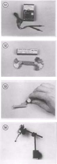
Screw Pitch Gauge
A screw pitch gauge (Figure 52) determines the thread pitch of bolts, screws, studs, etc. The gauge is made up of a number of thin plates. Each plate has a thread shape cut on one edge to match one thread pitch. When using a screw pitch gauge to determine a thread pitch size, try to fit different blade sizes onto the bolt thread until both threads match (Figure 53).
Magnetic Stand
A magnetic stand (Figure 54) is used to securely hold a dial indicator when checking the runout of a round object or when checking the end play of a shaft.
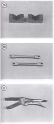
V-Blocks
V-blocks (Figure 55) are precision ground blocks used to hold a round object when checking its runout or condition. In motorcycle repair. V-blocks can be used when checking the runout of such items as valve stems, camshaft, balancer shaft, crankshaft, wheel axles and fork tubes.
Surface Plate
A surface plate can be used to check the flatness of parts or to provide a perfectly flat surface for minor resurfacing of cylinder head or other critical gasket surfaces. While industrial quality surface plates are quite expensive, the home mechanic can improvise. A thick metal plate can be put to use as a surface plate. The metal surface plate with a piece of sandpaper or dry wall surface sanding sheets glued to its surface can be used for cleaning and smoothing cylinder head and crankcase mating surfaces.
NOTE
Check with a local machine shop on the availability and cost of having a metal plate resurfaced/or use as a surface plate.
SPECIAL TOOLS
A few special tools may be required for major service. These are described in the appropriate chapters and are available either from a Suzuki dealer or other manufacturers as indicated.
This section describes special tools unique to this type of bike's service and repair.
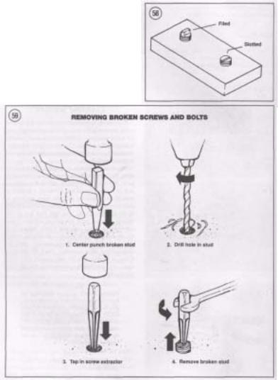
Spoke Wrench
This special wrench is used to tighten wheel spokes (Figure 56). Always use the correct size wrench to avoid rounding out and damaging the spoke nipple.
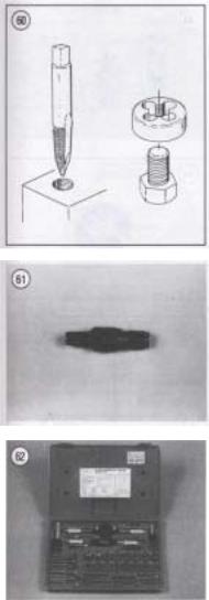
The Grabbit
The Grabbit (Figure 57) is a special tool used to hold the clutch boss when removing the clutch nut and to secure the drive sprocket when removing the sprocket nut.
Other Special Tools
A few other special tools may be required for major service. These are described in the appropriate chapters and are available from Suzuki dealers or other manufacturers as indicated.
CLEANING SOLVENT
With the environmental concern that is prevalent today concerning the disposal of hazardous solvents, the home mechanic should select a water soluble, biodegradable solvent. These solvents can be purchased through dealers, automotive parts houses and large hardware stores.
Selecting a solvent is only one of the problems facing the home mechanic when it comes to cleaning parts. You need some type of tank to clean parts as well as to store die solvent. There are a number of manufacturers offering different types and sizes of parts cleaning tanks. While a tank may seem a luxury to the home mechanic, you will find that it will quickly pay for itself through its efficiency and convenience. When selecting a parts washer, look for one that can recycle and store the solvent, as well as separate the sludge and contamination from the clean solvent. Most important, check the warranty, if any, as it pertains to the tank's pump. Like most tools, when purchasing a parts washer, you get what you pay for.
WARNING
Having a stack of clean shop rags on hand is important when performing engine work. However, to prevent the possibility of fire damage from spontaneous combustion from a pile of solventsoaked rags, store them in a lid-sealed metal container until they can be washed or discarded.
NOTE
To avoid absorbing solvent and other chemicals into your skin while cleaning parts, wear a pair of petroleum-resistant
rubber gloves. These can be purchased through industrial supply houses or well-equipped hardware stores.
MECHANIC'S TIPS
Removing Frozen Nuts and Screws
When a fastener rusts and cannot be removed, several methods may be used to loosen it. First, apply penetrating oil such as Liquid Wrench or WD-40 (available at hardware or auto supply stores). Apply it liberally and let it penetrate for
10-15 minutes. Rap the fastener several times with a small hammer; do not hit it hard enough to cause damage. Reapply the penetrating oil if necessary.
For frozen screws, apply penetrating oil as described, then insert a screwdriver in the slot and rap the top of the screwdriver with a hammer. This loosens the rust so the screw can be removed in the normal way. If the screw head is too chewed up to use this method, grip the head with vise-grip pliers and twist the screw out.
Avoid applying heat unless specifically instructed, as it may melt, warp or remove the temper from parts.
Removing Broken Screws or Bolts
When the head breaks off a screw or bolt, several methods are available for removing the remaining portion.
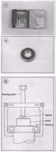
If a large portion of the remainder projects out, try gripping it with vise-grips. If the projecting portion is too small, file it to fit a wrench or cut a slot in it to fit a screwdriver. See Figure 58.
If the head breaks off flush, use a screw extractor. To do this, center punch the exact center of the remaining portion of the screw or bolt. Drill a small hole in the screw and tap the extractor into the hole. Back the screw out with a wrench on the extractor. See Figure 59.
Remedying Stripped Threads
Occasionally, threads are stripped through carelessness or impact damage. Often the threads can be cleaned up by running a tap (for internal threads on nuts) or die (for external threads on bolts) through the threads. See Figure 60. To clean or repair spark plug threads, a spark plug tap can be used (Figure
61).
NOTE
Tap and dies can be purchased individually or in a set as shown in Figure 62.
If an internal thread is damaged, it may be necessary to install a Helicoil (Figure 63) or some other type of thread insert. Follow the manufacturer's instructions when installing their insert.
Removing Broken or Damaged Studs
If a stud is broken or the threads severely damaged, perform the following. A tube of red Loctite (No. 271), 2 nuts, 2 wrenches and a new stud will be required during this procedure. Studs that are stripped or damaged will require the use of a stud remover.
1. Thread two nuts onto the damaged stud. Then tighten the 2 nuts against each other so that they are locked.
NOTE
If the threads on the damaged stud do not allow installation of the 2 nuts, you will have to remove the stud with a stud remover.
2.Turn the bottom nut counterclockwise and un screw the stud.
3.Threaded holes with a bottom surface should be blown out with compressed air as dirt buildup in the bottom of the hole may prevent the stud from being torqued properly. If necessary, use a bottoming tap to true up the threads and to remove any deposits.
4.Install 2 nuts on the top half of the new stud as in Step 1. Make sure they are locked securely.
5.Coat the bottom half of a new stud with red Loctite (No. 271),
6.Turn the top nut clockwise and thread the new stud securely.
7.Remove the nuts and repeat for each stud as required.
8.Follow Loctite's directions on cure time before assembling the component.
BALL BEARING REPLACEMENT
Ball bearings (Figure 64) are used throughout your Suzuki's engine and chassis to reduce power loss, heat and noise resulting from friction. Because ball bearings are precision made parts, they must be maintained by proper lubrication and maintenance. When a bearing is found to be damaged, it should be replaced immediately. However, when installing a new bearing, care should be taken to prevent damage to the new bearing. While bearing replacement is described in the individual chapters where applicable, the following can be used as a guideline.
NOTE
Unless otherwise specified, install bearings with the manufacturer's mark or number on the bearing facing outward.
Bearing Removal
While bearings are normally removed only when damaged, there may be times when it is necessary to
remove a bearing that is in good condition. Depending on the situation, you may be able to remove the bearing without damaging it. However, bearing removal in some situations, no matter how careful you are, will cause bearing damage. Care should always be given to bearings during their removal to prevent secondary damage to the shaft or housing. Note the following when removing bearings.
1.When using a puller to remove a bearing from a shaft, care must be taken so that shaft damage does not occur. Always place a piece of metal between the end of the shaft and the puller screw. In addition, place the puller arms next to the inner bearing race. See Figure 65.
2.When using a hammer to remove a bearing from a shaft, do not strike the hammer directly against the shaft. Instead, use a brass or aluminum spacer be tween the hammer and shaft (Figure 66). In addi tion, make sure to support both bearing races with wood blocks as shown in Figure 66.
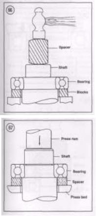
3.The most ideal method of bearing removal is with a hydraulic press. However, certain procedures must be followed or damage may occur to the bearing, shaft or case half. Note the following when using a press:
a.Always support the inner and outer bearing races with a suitable size wood or aluminum spacer ring (Figure 67). If only the outer race is supported, the balls and/or the inner race will be damaged.
b.Always make sure the press ram (Figure 67) aligns with the center of the shaft. If the ram is not centered, it may damage the bearing and/or shaft.
c.The moment the shaft is free of the bearing, it will drop to the floor. Secure or hold the shaft to prevent it from falling.
Bearing Installation
1.When installing a bearing in a housing, pressure must be applied to the outer bearing race (Figure 68). When installing a bearing on a shaft, pressure must be applied to the inner bearing race (Figure
69).
2.When installing a bearing as described in Step 1, some type of driver will be required. Never strike the bearing directly with a hammer or the bearing will be damaged. When installing a bearing, a piece of pipe or a socket with an outer diameter that matches
 Loading...