


SUZUKI |
1995 |
|
OWNER'S MANUAL
Keep With Vehicle At All Times.
Contains Important Information
On Safety, Operation & Maintenance.
SUZUKI
Caring for Customers
Part No. 99011-60A26-03E
June, 1994 
60A23 00010
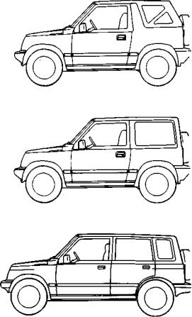
This owner's manual applies to the following models of the SIDEKICK series:
p
CANVAS TOP
2-DOOR HARDTOP
4-D00R HARDTOP
© COPYRIGHT SUZUKI MOTOR CORPORATION 1994
TABLE OF CONTENTS
FUEL RECOMMENDATION |
1 |
BEFORE DRIVING |
2 |
STEERING COLUMN CONTROLS |
3 |
INSTRUMENT PANEL |
4 |
OTHER CONTROLS AND EQUIPMENT |
5 |
OPERATING YOUR VEHICLE |
6 |
DRIVING TIPS |
7 |
VEHICLE LOADING AND TOWING |
8 |
INSPECTION AND MAINTENANCE |
9 |
EMERGENCY SERVICE |
10 |
APPEARANCE CARE |
11 |
GENERAL INFORMATION Including "Reporting Safety Defects" |
12 |
FUSES AND PROTECTED CIRCUITS |
13 |
SPECIFICATIONS |
14 |
INDEX |
15 |
|
|
60A2300031
This manual is an essential part of your |
IF YOU HAVE ANY PROBLEMS WITH |
|
vehicle and should be kept with the vehi- |
YOUR SUZUKI: |
|
cle at all times. Please read this manual |
Please review the New Vehicle Warranty |
|
carefully and review it from time to time. |
||
Information booklet supplied with your |
||
It contains important information on safe- |
||
Suzuki. Should you have a question or |
||
ityr"operation, and maintenance. It is |
problem regarding the warranty or service |
|
especially important that this manual |
||
of your vehicle, please take the following |
||
remain with the vehicle at the time of |
||
action: |
||
resale. The next owner will need this in- |
||
|
||
formation also. |
Consult the Service Manager and the |
|
Your SUZUKI multipurpose vehicle is |
Owner of the Suzuki Automotive Dealer- |
|
ship. Explain your problem and ask their |
||
designed and built to be capable of per- |
||
assistance in resolving your problem. The |
||
forming both on pavement and off road. |
||
Owner of the dealership is in the very best |
||
You should therefore remember that your |
||
position to assist you as he or she is vital- |
||
vehicle is distinctly different from ordinary |
ly concerned with your continued |
|
passenger cars in handling as well as in |
satisfaction. |
|
structure. As with other vehicles of this |
||
|
||
type, failure to operate this vehicle cor- |
If you are still in need of additional infor- |
|
rectly may result in loss of control or an |
mation, or if you are dissatisfied, request |
|
accident. Be sure to read "on-pavement" |
that your dealer arrange a meeting with |
|
and "off-road" driving guidelines which |
your District Service Manager. |
|
follow. It is very important to familiarize |
|
|
yourself with the proper operation of this |
|
|
vehicle before you start driving. |
|
American Suzuki Motor Corporation
Automotive Customer Relations
3251 East Imperial Highway
Brea, CA 92621-6722
Please be certain to provide us with the following information: the model. Vehicle Identification Number, mileage, accessories involved, event dates, dealer name, dealer personnel consulted, your problem or question, and any other comments you have. When we receive your correspondence, we will be glad to contact the Owner of your dealership and assist in resolving your concern.
For owners outside the continental United States, please refer to the distributor's address listed in your Warranty Information booklet.
0-1

60A23-00032
All information in this manual is based on the latest product information available at the time of publication. Due to improvements or other changes, there may be discrepancies between information in this manual and your vehicle. Suzuki reserves the right to make production changes at any time, without notice and without incurring any obligation to make the same or similar changes to vehicles previously built or sold.
SUZUKI MOTOR CORPORATION believes in conservation and protection of Earth's natural resources.
To that end, we encourage every vehicle owner to recycle, trade in, or properly dispose of, as appropriate, used motor oil, coolant, and other fluids; batteries; and tires.
SUZUKI MOTOR CORPORATION
60A23-OO040 |
60A23-00050 |
IMPORTANT
 WARNING/
 CAUTION/NOTE
Please read this manual and follow its instructions carefully. To emphasize special information, the symbol  and the words WARNING, CAUTION, and NOTE have special meanings. Pay special attention to the messages highlighted by these signal words:
Indicates a potential hazard that could result in death or injury.
A CAUTION
Indicates a potential hazard that could result in vehicle damage.
MODIFICATION WARNING
Do not modify this vehicle. Modification could adversely affect safety, handling, performance, or durability and may violate governmental regulations. In addition, damage or performance problems resulting from modification may not be covered under warranty.
NOTE:
Indicates special information to make maintenance easier or instructions clearer.
0-2

FUEL RECOMMENDATION
60A23-01000
FUEL RECOMMENDATION
Fuel recommendation |
1-1 |
6OA23-O2O00
BEFORE DRIVING
Keys |
2-1 |
Door Locks |
2-1 |
Windows |
2-4 |
Mirrors |
2-5 |
Seat Adjustment |
2-7 |
Head Restraints |
2-9 |
Seat Belts and Child Restraint Systems |
2-10 |

FUEL RECOMMENDATION
60A23-01010
FUEL RECOMMENDATION
Your vehicle requires regular unleaded gasoline with a minimum rating of 87
pump octane (r+m/2 method). In some
areas, the only fuels that are available are oxygenated fuels.
Oxygenated fuels which meet the minimum octane requirement and the requirements described below may be used in your vehicle without jeopardizing the New Vehicle Limited Warranty.
NOTE:
Oxygenated fuels are fuels which contain oxygen-carrying additives such as MTBE or alcohol.
Gasoline Containing MTBE
Unleaded gasoline containing MTBE (methyl tertiary butyl ether) may be used in your vehicle if the MTBE content is not greater than 15%. This oxygenated fuel does not contain alcohol.
Gasoline/Ethanol Blends
Blends of unleaded gasoline and ethanol (grain alcohol), also known as gasohol, may be used in your vehicle if the ethanol content is not greater than 10%.
Gasoline/Methanol Blends
Avoid using blends of unleaded gasoline and methanol (wood alcohol) whenever possible. Do NOT USE fuels containing more than 5% methanol under any circumstances. Fuel system damage or vehicle performance problems resulting from the use of such fuels are not the responsibility of SUZUKI and may not be covered under the New Vehicle Limited Warranty.
Fuels containing 5% or less methanol may be suitable for use in your vehicle if they contain cosolvents and corrosion inhibiters.
Fuel Pump Labeling |
|
In some states, pumps that dispense |
|
oxygenated fuels are required to be label- |
|
ed for the type and percentage of ox- |
|
ygenate and whether important additives |
|
are present. Such labels may provide |
|
enough information for you to determine |
|
if a particular blend of fuel meets the re- |
\ |
quirements listed above. In other areas, |
f |
pumps may not be clearly labeled as to |
|
the content or type of oxygenate and ad- |
i |
ditives. If you are not sure that the fuel |
j |
you intend to use meets these re- |
|
quirements, check with the service sta- |
|
tion operator or the fuel supplier. |
|
NOTE: |
|
To help clean the air, SUZUKI recom- |
|
mends you use the oxygenated fuels. |
|
However, if you are not satisfied with the |
|
driveability or fuel economy of your ve- |
|
hicle when you are using an oxygenated |
|
fuel, switch back to the regular unleaded |
|
gasoline. |
|
A CAUTION
Be careful not to spill fuel containing alcohol while refueling. Fuels containing alcohol can cause paint damage, which is not covered under the New Vehicle Limited Warranty.
1-1
60A23 02010
KEYS
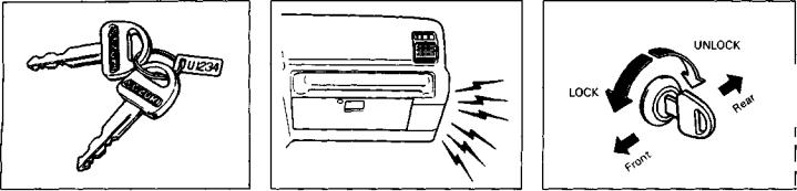
Your vehicle comes with a pair of identical keys. Keep the spare key in a safe place. One key can open all of the locks on the vehicle.
The key identification number is stamped on a metal tag provided with the keys. Keep the tag in a safe place. If you lose your keys, you will need this number to have new keys made. Write the number below for your future reference.
KEY NUMBER:
BEFORE DRIVING
60A23-02020
DOOR LOCKS
Ignition Key Reminder |
Side Door Locks |
A buzzer sounds to remind you to remove |
To lock a front door from outside the |
the ignition key if it is in the ignition |
vehicle: |
switch when the driver's door is opened. |
a) Insert the key and turn the top of the |
|
key toward the front of the vehicle, or |
|
b) Push in the lock knob and hold the |
|
door handle up as you close the door. |
|
To unlock a front door from outside the |
|
vehicle, insert the key and turn the top of |
|
the key toward the rear of the vehicle. |
2-1
BEFORE DRIVING
2-door model
UNLOCK
LOCK
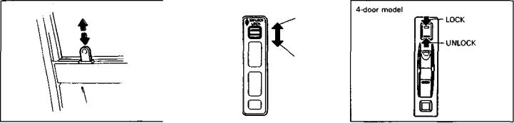
To lock a door from inside the vehicle, push down the lock knob. Pull up the lock knob to unlock the door.
• For 4-DOOR MODEL
To lock a rear side door from outside the vehicle, push in the lock knob and close the door. You do not need to hold the door handle up as you close the door.
Power Door Locks (if Equipped)
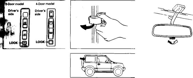
The power door lock switch is located on the driver's side door panel. For vehicles with this feature, you can lock and unlock all side doors and rear door simultaneously by:
a)Using the key in the driver's side door lock or in the rear door lock, or
b)Operating the power door lock switch.
•For 2-Door model
Pushing down on the switch locks both side doors and rear door, and pulling up on the switch unlocks both side doors and rear door.
•For 4-Door model
Pushing the upper part of the switch locks all side doors and rear door, and pushing the lower part of the switch unlocks all side doors and rear door.
You can also lock all side doors and rear door by pushing in the door lock knob on the driver's door, but pulling up the lock knob on the driver's door will unlock the driver's door only.
NOTE:
*Using the key or moving the lock knob on the passenger's door will lock or unlock the passenger's door only.
2-2
BEFORE DRIVING
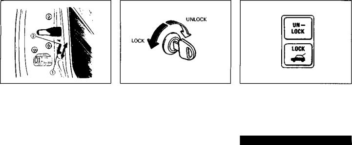
Child Lock System (If Equipped) |
Rear Door Lock |
Power Rear Door Lock (If Equipped) |
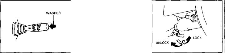
Each of the rear doors is equipped with a child lock which can be used to help prevent unwanted opening of the door from inside the vehicle. When the lock lever is in the "LOCK" position (1), the rear door can only be opened from outside. When the lock lever is in the "RELEASE" position (2), the rear door can be opened from inside or outside.
To lock the rear door, insert the key and turn it counterclockwise. To unlock the door, turn the key clockwise.
The power rear door lock buttons are located on the instrument panel. By pushing the appropriate button you can lock or unlock the rear door from inside the vehicle.
Always lock all doors when driving. Locking the doors helps to prevent occupants from being thrown from the vehicle in the event of an accident. It also helps prevent unintended opening of the doors.
2-3
BEFORE DRIVING
60A23-02030
WINDOWS
2-Door model |
|
4-Door model |
|
|
Driver's |
Passenger's |
Driver's |
|
|
side |
side |
|
|
|
side |
|
Passenger's |
||
|
|
|
||
|
|
|
|
door |
|
|
|
Console |
(front, rear) |
|
|
|
|
Manual Window Control (If Equipped)
Raise or lower the door windows by turning the hand crank located on the door panel.
Power Window Controls (If Equipped)
The driver's door has a switch to operate the driver's window ©, and a switch to operate the front passenger's window @. In 4-door models, the console between the front seats has switches ®, ©, to operate the rear left and right passenger windows, respectively.
The passenger's door only has a switch to operate the passenger's window (D. The power windows can only be operated when the ignition switch is in the "ON" position.
•For 2-Door model
To open a window, push the lower part of the switch and to close a window push the upper part of the switch.
•For 4-Door model
To open a window, push the top part of the switch and to close the window lift up the top part of the switch.
The driver's window has an auto-down feature for added convenience (at toll booths or drive-through restaurants, for example). This means you can open the window without holding the window switch in the "Down" position. Press the driver's window switch completely down and release it. To it reaches the bottom, pull the switch up briefly.
2-4 |
10 |
BEFORE DRIVING
60A23-08040
MIRRORS
The driver's door also has a lock button for the passenger's window(s). When you push in the lock button, the passenger's window(s) can not be raised or lowered by operating either of the switches (2) or (3), and (4) or (5) in 4-door models. To restore normal operation, release the lock button by pushing on it again.
You should always push in the lock button when there are children in the vehicle. Children can be seriously injured if they get part of their body caught by the window during operation.
Rear Side Window (2-door model)
To open the rear side window, move the lock lever forward and outward. To close the window, pull the lever inward and rearward until it clicks into position.
Day driving |
Night driving |
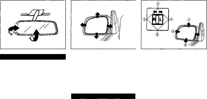
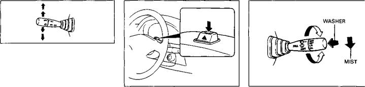
Day-Night Rearview Mirror (If Equipped)
To adjust the inside rearview mirror, set the selector tab to the day position, then move the mirror up, down, or sideways to obtain the best view.
When driving at night, you can move the selector tab to the night position to reduce glare from the headlights of vehicles behind you.
11 |
2-5 |
BEFORE DRIVING
Always adjust the mirror with the selector set to the day position. Only use the night position if it is necessary to reduce glare from the headlights of vehicles behind you. Be aware that in this position you may not be able to see some objects that could be seen in the day position.
Outside Rearview Mirrors
Adjust the outside rearview mirrors so you can just see the side of your vehicle in the mirrors.
The passenger's side mirror is a convex (curved surface) mirror. Objects seen in this mirror will look smaller and appear farther away than when seen in a flat mirror.
Be careful when judging the size or distance of a vehicle or other object seen in the side convex mirror. Be aware that objects look smaller and appear farther away than when seen in a flat mirror.
Power Mirror Control (If Equipped)
The switch to control the power rearview mirrors is located on the instrument panel. You can only adjust the mirrors when the ignition switch is in the "ON" position. To adjust the mirrors:
1) Move the selector switch to the left or right to select the mirror you wish to adjust.
2)Press the outer part of the switch that corresponds to the direction you wish to move the mirror.
3)Return the selector switch to the center position to help prevent unintended adjustment.
2-6 |
12 |

60A23-02050
SEAT ADJUSTMENT
Never attempt to adjust the driver's seat or seatback while driving. The seat or seatback could move unexpectedly, causing loss of control. Be sure that the driver's seat and seatback are properly adjusted before you start driving.
BEFORE DRIVING
Adjusting Seat Position
The adjustment lever for each front seat is located under the front of the seat, on the outboard side. The adjustment levers for each split folding rear seat in the 2-door model are located under the front and rear of the seat, on the inboard side. To adjust the seat position, pull up on the adjustment lever and slide the seat forward or rearward. After adjustment, try to move the seat forward and rearward to ensure that it is securely latched.
To avoid excessive seat belt slack, which reduces the effectiveness of the seat belts as a safety device, make sure that the front seats and split folding rear seats are adjusted before the seat belts are fastened.
2-7

BEFORE DRIVING
Split folding rear seat in the 2-door model |
Other rear seats |
5 positions
2 positions
r-l
Adjusting Seatbacks
The front and rear seatbacks can be adjusted to different angles. To adjust the seatback angle of front seats, pull up the lever on the outboard side of the seat, move the seatback to the desired position, and release the lever to lock the seatback in place.
To adjust the seatback angle of rear seats: a) Pull up the knob on the top of a split
folding seat. or
Pull up both knobs on the top of a onepiece seat.
b)Move the seatback to one of the lock positions. Split folding seats in the 2-door model have five lock positions and other rear seats have two lock positions.
c)Release the knob(s) to lock the seatback in position. After adjustment, try moving the seatback to make sure it is securely locked.
Seatbacks should always be in a fairly upright position when the vehicle is being used, or seat belt effectiveness may be reduced. Seat belts are designed to offer maximum protection when seatbacks are in the fully upright position.
2-8 |
14 |
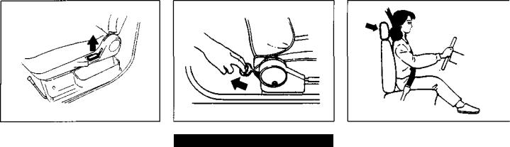
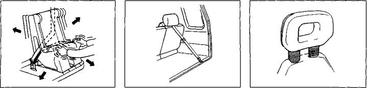
Walk-In Type Seats (2-door model)
The front seats are walk-in type seats, which move to provide easy entry to and exit from the rear seat(s). You can move a walk-in seat from outside the vehicle by pulling up the lever on the outboard side of the seat. You can move the front passenger's seat from inside the vehicle by pulling on the rear ring. When you release a walk-in seat, it will automatically slide forward and the seatback will fold forward.
Before returning a walk-in seat to its normal seating position, make sure that the feet of the passenger in the rear seat are out of the way. After returning the seat to its normal seating position, make sure it is securely latched.
BEFORE DRIVING
60A23-02060
HEAD RESTRAINTS (If Equipped)
Head restraints are designed to help reduce the risk of neck injuries in case of an accident.
Adjust the head restraint to the position which places the top of the head restraint closest to the top of your ears.
Never drive the vehicle with the head restraints removed.
*Do not attempt to adjust the head restraint while driving.
15 |
2-9 |

BEFORE DRIVING
60A23-02070
SEAT BELTS AND CHILD
RESTRAINT SYSTEMS
(For front seat in the 2-door model)
Pull upward on the restraint to raise it to the first position. To raise it higher (or to lower), pull upward on the restraint (or push it down) while pushing in the release.
(For front seat in the 4-door model)
To raise the head restraint, pull upward on the restraint until it clicks. To lower the restraint, push down on the restraint while holding in the lock lever. If a head restraint must be removed (for cleaning, replacement, etc.), push in the lock lever and pull the head restraint all the way out.
(For split rear seat in the 4-door model) The head restraints do not have different height positions; they should remain fully inserted. If a head restraint must be removed (for cleaning, replacement, etc.), push in the release and pull the head restraint all the way out. To reinstall, fully insert the head restraint while pushing in the release.
2-10 |
16 |
BEFORE DRIVING
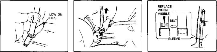
Front and Rear Lap-Shoulder Belts
Pull the buckle tongue attached to the seat belt across your body and press it into the buckle catch until you hear a "click". The buckle catch is located at the inboard side of the seat. To reduce the risk of sliding under the belt during a collision, position the lap portion of the belt across your lap as low on your hips as possible and adjust it to a snug fit by pulling the shoulder portion of the belt upward through the latch plate.
The length of the diagonal shoulder strap adjusts itself to allow freedom of movement. The seat belt has an emergency
locking retractor (ELR), which is designed to lock the seat belt only during a sudden stop or impact. To unfasten the belt, press the release button on the buckle catch.
NOTE:
The front passenger's seat belt and the rear seat belts havs emergency locking retractors (ELRs) that can be temporarily converted to function as automatic locking retractors (ALRs). The ALR mode should be used if you need to secure a child restraint system in the seat. Refer to the CHILD RESTRAINT section for details.
Seat Belt Inspection
Periodically inspect the seat belts to make sure they work properly and are not damaged. Check the webbing, buckles, latch plates, retractors, anchorages, and guide loops. Replace any seat belts which do not work properly or are damaged.
The front passenger's seat lap-shoulder belt has a small loop of webbing lightly stitched into the belt under the plastic sleeve, as shown in the illustration. Periodically inspect the belt to see if the loop has been pulled out (making the "REPLACE BELT" label .visible). If the "REPLACE BELT" label is visible, you must replace the belt to help restore optimum restraint system effectiveness.
17 |
2-11 |
BEFORE DRIVING
Be sure to inspect all seat belt assemblies after any collision. Any seat belt assembly which was in use during a collision (other than a very minor one) should be replaced, even if damage to the assembly is not obvious. Any seat belt assembly which was not in use during a collision should be replaced if it does not function properly or is damaged in any way.
Child Restraint Systems
Suzuki highly recommends that you use a child restraint system to restrain infants and small children. Many different types of child restraint systems are available; make sure that the restraint system you select meets Federal Motor Vehicle Safety Standards.
All child restraint systems are designed to be secured in vehicle seats by lap belts or the lap portion of lap-shoulder belts. Whenever possible, Suzuki recommends that child restraint systems be installed on the rear seat. According to accident statistics, children are safer when properly restrained in rear seating positions than in front seating positions.
When using a child restraint in the front passenger's seat, adjust the passenger's seat as far back as possible.
Children could be endangered in a crash if their child restraints are not properly secured in the vehicle. When installing a child restraint system, be sure to follow the instructions below.
Installation-Child Restraint with no Top Strap
Install your child restraint system according to the instructions provided by the child restraint system manufacturer. If you install the child restraint system in the front seat, be sure to slide the seat to the rearmost position. After making sure that the seat belt is securely latched:
1) Pull all of the remaining webbing out of the retractor. You will hear a click, which means that the emergency locking retractor (ELR) has converted to function as an automatic locking retractor (ALR).
2) Allow the extra webbing to retract, and pull the webbing toward the retractor to take up any slack. Make sure that the lap portion of the belt is tight around the child restraint system and
the shoulder portion of the belt is positioned so that it can not interfere with the child's head or neck.
3) Make sure that the retractor has converted to the ALR mode by trying to pull webbing out of the retractor. If the retractor is in the ALR mode, the belt will be locked.
If the retractor is not in the ALR mode, the child restraint system can move or tip over when your vehicle turns or stops abruptly.
4)Try moving the child restraint system in all directions, to make sure it is securely installed. If you need to
2-12 |
18 |
BEFORE DRIVING
tighten the belt, pull more webbing toward the retractor.
When you unbuckle the seat belt and allow it to retract to a certain length, the retractor will automatically revert back to the normal ELR mode.
Installation—Child Restraint with Top Strap
If you need to install a child restraint that requires a top strap, follow the instructions below:
•For 4-door model:
Have your dealer install the top strap anchor bracket for your child restraint system or contact your dealer for instructions on how to install the anchor
bracket. Anchorages are located on either side of the rear of the luggage compartment. Once the anchor bracket has been installed, install the child restraint system as follows:
1)Secure the child restraint on the rear seat using the procedure described above for securing a restraint system that does not require a top strap.
2)Hook the top strap to the anchor bracket and tighten the top strap according to the instructions provided by the child restraint system manufacturer. When routing the top strap, be sure to pass it between the head restraint and the rear seatback as shown.
For 2-door model
If the right front passenger's seat of your vehicle has an adjustable head restraint, you can install a child restraint which reguires a top strap on the seat by following the instructions below. If the right front passenger's seat of your vehicle has an integrated head restraint, there is no place in your vehicle to install a child restraint which reguires a top strap.
19 |
2-13 |
BEFORE DRIVING
A child restraint which requires a top strap may only be installed in the right front passenger's seat. There is no place behind the rear seat to install a top strap anchor, so a child restraint that requires a top strap can not be properly secured in the rear seat.
When a child restraint which requires a top strap is secured in the right front passenger's seat, no one can sit in the right rear seat position.
Install the child restraint system as follows:
1) Secure the child restraint on the right front passenger's seat using the procedure described above for securing a restraint system that does not reguire a top strap.
2-14
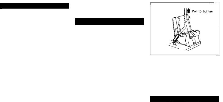
2)Pass the top strap between the head restraint and the seatback and snap the top strap hook through the hole on the latch plate of the right rear lapshoulder belt.
3)Remove any slack from the top strap according to the instructions provided by the restraint system manufacturer.
4)Pull all of the remaining webbing out of the rear seat belt retractor. You will hear a click, which indicates that the retractor has converted to the ALR mode.
5)Allow the extra webbing to retract, and pull the webbing toward the retractor to take up any slack.
6)Make sure the child restraint is secured, and the top strap and webbing are tight.
To unhook the top strap, loosen the strap by tilting the seatback rearward.
20
.

*Never allow persons to ride in the cargo area of a vehicle. In the event of an accident, there is a much greater risk of injury for persons who are not riding in a seat with their seat belt securely fastened.
*Seat belts should always be adjusted so the lap portion of the belt is worn low across the pelvis, not across the waist. Shoulder straps should be worn on the outside shoulder only, and never under the arm. Seat belts should never be worn with the straps twisted and should be adjusted as tightly as is comfortable to provide the protection for which they have been designed. A slack belt will provide less protection than one which is snug.
*Make sure that each seat belt buckle is inserted into the proper buckle catch. It is possible to cross the buckles in the rear seat.
*Do not wear your seat belt over hard or breakable objects in your pockets or on your clothing. If an
(Continued)
(Continued)
accident occurs, objects such as glasses, pens, etc. under the seat belt can cause injury.
*Never use the same seat belt on more than one occupant and never attach a seat belt over an infant or child being held on an occupant's lap. Such seat belt use could cause serious injury in the event of an accident.
*Pregnant women should use seat belts, although specific recommendations about restraint use should be made by the woman's physician.
*Periodically inspect seat belt assemblies for excessive wear and damage. Seat belts should be replaced if webbing becomes frayed, contaminated, or damaged in any way. It is essential to replace the entire seat belt assembly after it has been worn in a severe impact, even if damage to the assembly is not obvious.
*Infants and small children should never be transported unless they
(Continued)
BEFORE DRIVING
(Continued)
are properly restrained. Restrain systems for infants and small children can be purchased commercially and should be used. Make sure that the system you purchase meets Federal Motor Vehicle Safety Standards. Read and follow all the directions provided by the manufacturer.
*Avoid contamination of seat belt webbing by polishes, oils, chemicals, and particularly battery acid. Cleaning may safely be carried out using mild soap and water.
*For children, if the shoulder belt irritates the neck or face, move the child closer to the center of the vehicle.
*Seatbacks should always be in a fairly upright position when the vehicle is being used, or seat belt effectiveness may be reduced. Seat belts are designed to offer maximum protection when seatbacks are in the fully upright position.
21 |
2-15 |

STEERING COLUMN CONTROLS
60A23-03000
STEERING COLUMN CONTROLS
Ignition Switch |
3-1 |
Lighting/Turn Signal Control Lever |
3-3 |
Hazard Warning Switch |
3-4 |
Windshield Wiper and Washer Lever |
3-4 |
Tilt Steering Lock Lever (If Equipped) |
3-5 |
Cruise Control (If Equipped) |
3-6 |
Horn |
3-7 |
23
STEERING COLUMN CONTROLS
60A23-03010
IGNITION SWITCH
MANUAL TRANSMISSION
PUSH
TURN TO "LOCK"
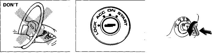
To avoid possible injury, do not operate controls by reaching through the steering wheel.
The ignition switch has the following four positions:
LOCK
This is the normal parking position. It is the only position in which the key can be removed.
Manual Transmission Vehicles
You must push in the key to turn it to the "LOCK" position. It locks the ignition, and prevents normal use of the steering wheel after the key is removed.
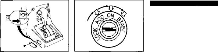
Automatic Transmission Vehicles
The shift lever must be in the "P" (Park) position to turn the key to the "LOCK" position. It locks the ignition and prevents normal use of the steering wheel and shift lever.
3-1 |
24 |
STEERING COLUMN CONTROLS
If the shift lever can not be shifted out of Park in the normal way, pushing the return plate © rearward with the key in the "ON" or "ACC" position will permit movement of the shift lever out of "P". (see "Emergency Shifting out of "P" (Park)" of "USING THE TRANSMISSION" in "OPERATING YOUR VEHICLE " section.). The shift lever can be moved back to "P" without pushing the return plate © rear ward.
To release the steering lock, insert the key and turn it clockwise to one of the other positions. If you have trouble turning the key to unlock the steering, try turning the steering wheel slightly to the right or left while turning the key.
ACC
Accessories such as the radio can operate, but the engine is off.
ON
This is the normal operating position. All electrical systems are on.
START
This is the position for starting the engine using the starter motor. The key should be released from this position as soon as the engine starts.
For manual transmission vehicles, never remove the ignition key while the vehicle is moving. The steering wheel will lock and you will not be able to steer the vehicle.
Do not leave children alone in a parked vehicle, and always remove the keys. Unattended children could cause accidental movement of the vehicle, which could result in severe personal injury.
A CAUTION
Do not turn the starter motor for more than five seconds at a time. If the engine does not start, wait five to ten seconds before trying again. If the engine does not start after several attempts, check the fuel and ignition systems or consult your SUZUKI dealer.
Do not leave the ignition switch in the "ON" position if the engine is not running or the battery will discharge.
25 |
3-2 |
STEERING COLUMN CONTROLS
60A23 03020
LIGHTING/TURN SIGNAL CONTROL LEVER
This control lever is located on the outboard side of the steering column. Operate the lever as described below.
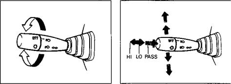
Lighting Operation
To turn the lights on or off, twist the knob on the end of the lever. There are three positions: in the "OFF" position all lights are off; in the middle position the front parking lights, tail-lights, licence plate light, and instrument lights are on, but the headlights are off; in the third position the headlights come on in addition to the other lights.
With the headlights on, push the lever forward to switch to the high beams or pull the lever toward you to switch to the low beams. When the high beams are on, a light on the instrument panel will come on. To momentarily activate the high beams as a passing signal, pull the lever slightly toward you and release it when you have completed the signal.
Day time Running Light (D.R.L.) System (For Canada)
The headlights light, but are dimmer than the low beam, when the following three conditions are all met. Also, the D.R.L. indicator light on the instrument panel comes on.
Conditions for D.R.L. system operation:
1.The engine is running.
2.The parking brake is released.
3.The lighting switch is at either the "OFF" or the "middle" position.
NOTE:
Be sure to turn the lighting switch to the third position at night or at any time of the day when driving or weather conditions require the headlights to operate at full brightness and the taillights to be on.
Lights "On" Reminder
A buzzer/chime sounds to remind you to turn off the lights if they are left on when the ignition switch is turned to the "OFF", "LOCK", or "ACCESSORY" position.
3-3 |
21 |
Turn Signal Operation
With the ignition switch in the "ON" position, move the lever up or down to activate the right or left turn signals.
Normal Turn Signal
Move the lever all the way up to signal a right turn or all the way down to signal a left turn. When the turn is completed, the signal will cancel and the lever will return to its normal position.
Lane Change Signal
In some turns, such as changing lanes, the steering wheel is not turned far enough to cancel the turn signal. For convenience, you can flash the turn signal by moving the lever part way and holding it there. The lever will return to its normal position when you release it.
60A 23-03030
HAZARD WARNING SWITCH
Push down the hazard warning switch to activate the hazard warning lights. All four turn signal lights and both turn signal indicators will flash simultaneously. To turn off the lights, push the switch again.
Use the hazard warning lights to warn other traffic during emergency parking or when your vehicle can otherwise become a traffic hazard.
STEERING COLUMN CONTROLS
60A23-03040
WINDSHIELD WIPER AND WASHER LEVER
Windshield Wipers
To turn the windshield wipers on, twist the knob on the end of the lever to one of the three operating positions. In the "INT" position (if equipped), the wipers operate intermittently (once every 3 to 5 seconds). The "INT" position is very convenient for driving in mist or light rain. In the "LO" position, the wipers operate at a steady low speed. In the "HIGH" position, the wipers operate at a steady high speed. To turn off the wipers, twist the knob back to the "OFF" position. To wipe mist off the windshield, you can operate the wipers for just a few cycles by pushing down on the wiper and washer lever. The wipers will operate without spraying washer fluid until you release the lever.
27 |
3-4 |
STEERING COLUMN CONTROLS
Windshield Washer
To spray windshield washer fluid, pull the lever toward you. The windshield wipers will automatically turn on at low speed if they are not already on and the "INT" position is equipped.
To prevent windshield icing in cold weather, turn on the defroster to heat the windshield before and during windshield washer use.
Do not use radiator antifreeze in the windshield washer reservoir. It can severely impair visibility when sprayed on the windshield, and can also damage your vehicle's paint.
A CAUTION
To help prevent damage to windshield wiper and washer system components, you should take the following precautions:
*Do not continue to hold in the lever when there is no windshield washer fluid being sprayed or the washer motor can be damaged.
*Do not attempt to remove dirt from a dry windshield with the wipers or you can damage the windshield and the wiper blades. Always wet the windshield with washer fluid before operating the wipers.
*Clear ice or packed snow from the wiper blades before using the wipers.
*Check the washer fluid level regularly. Check it often when the weather is bad.
*Only fill the washer fluid reservoir 3/4 full during cold weather to allow room for expansion if the temperature falls low enough to freeze the solution.
60A23-03050
TILT STEERING LOCK LEVER
(If Equipped)
The tilt steering lock lever is located on the left side of the steering column. To adjust the steering wheel height:
1) Push down on the lock lever to unlock the steering column.
2)Tilt the steering wheel to the desired height and lock the steering column by pulling the lock lever all the way up.
3)Try moving the steering wheel up and down to make sure it is securely locked in position.
Never attempt to adjust the steering wheel height while the vehicle is moving or you could lose control of the vehicle.
3-5 |
28 |
60A23-03060
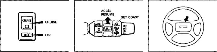
CRUISE CONTROL (If Equipped)
To help avoid loss of vehicle control, do not use the cruise control system when driving in heavy traffic, on slippery or winding roads, or on steep downgrades.
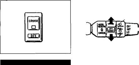
The cruise control system allows you to maintain a steady speed without keeping your foot on the accelerator pedal. The controls for operating the cruise control system are on the windshield wiper lever and there is an on/off switch for the system on the instrument panel. When the system is on, an indicator light on the instrument panel switch will be lit. You can use the cruise control system at
STEERING COLUMN CONTROLS
ACCEL
RESUME
SET COAST
CANCEL
speeds of about 25 mph (40 km/h) or higher.
To Set Cruising Speed
Turn on the cruise control system by pushing the "CRUISE" button on the instrument panel. Accelerate to the desired speed, push the "SET COAST" button on the control lever all the way in, and then slowly release the button. Take your foot off the accelerator pedal and the set speed will be maintained.
With the cruise control on, you can increase speed for passing by using the accelerator pedal. When you take your foot off the pedal, your vehicle will return to the set speed.
To Change Cruising Speed
To reset the cruise control to a slower speed, hold the "SET COAST" button in until the vehicle has slowed to the desired speed, then slowly release the button. The new speed will be maintained.
To reset the cruise control to a faster speed, use either of the following procedures:
a)Turn the control lever to the "ACCEL RESUME" position and hold it there. Vehicle speed will steadily increase. When you release the lever, the new speed will be maintained.
b)Accelerate to the desired speed using the accelerator pedal and press the "SET COAST" button all the way in. When you slowly release the button, the new speed will be maintained.
To Cancel
To cancel cruise control operation, use one of the following procedures:
a) Slightly depress the brake pedal or clutch pedal, or turn the control lever to the "CANCEL" position. Cruise control operation will be cancelled until you reset a cruising speed using "ACCEL RESUME" or.the "SET COAST" button.
29 |
3-6 |
STEERING COLUMN CONTROLS
b)Push the cruise control "OFF" button on the instrument panel. Cruise control operation will be cancelled until you turn on the system by pushing the "CRUISE" button and reset a cruising speed using the "SET COAST" button.
Cruise control operation will also be cancelled any time the vehicle speed falls below 25 mph (40 km/h). The cruise control system will be turned off each time the ignition switch is turned off.
To "Resume" a Previously Set Speed
After canceling cruise control operation without turning off the instrument panel switch, you can "resume" a previously set speed by accelerating to 25 mph (40 km/h) or more and holding the control lever in "ACCEL RESUME" position for about one second. When you release the lever the vehicle will accelerate to and maintain the previously set speed.
60A23-03070
HORN
Press the center piece of the steering wheel to sound the horn. The horn will sound with the ignition switch in any position.
3-7 |
30 |
 Loading...