


FOREWORD
This manual contains an introductory description on the SUZUKI GZ250 and procedures for its inspection/service and overhaul of its main components.
Other information considered as generally known is not included.
Read the GENERAL INFORMATION section to familiarize yourself with the motorcycle and its maintenance. Use this section as well as other sections as a guide for proper inspection and service. This manual will help you know the motorcycle better so that you can assure your customers of fast and reliable service.
This manual has been prepared on the basis of the latest specifications at the time of publication. If modifications have been made since then, differences may exist between the content of this manual and the actual motorcycle.
Illustrations in this manual are used to show the basic principles of operation and work procedures. They may not represent the actual motorcycle exactly in detail. This manual is written for persons who have enough knowledge, skills and tools, including special tools, for servicing SUZUKI motorcycles. If you do not have the proper knowledge and tools, ask your authorized SUZUKI motorcycle dealer to help you.
WARNING
Inexperienced mechanics or mechanics without the proper tools and equipment may not be able to properly perform the service described in this manual. Improper repair may result in injury to the mechanic and may render the motorcycle unsafe for the rider and passenger.
GROUP INDEX
GENERAL INFORMATION
PERIODIC MAINTENANCE
ENGINE
FUEL AND LUBRICATION
SYSTEM
CHASSIS
ELECTRICAL SYSTEM
SERVICING INFORMATION
SUZUKI MOTOR CORPORATION
Motorcycle Service Department
© COPYRIGHT SUZUKI MOTOR CORPORATION 1998
HOW TO USE THIS MANUAL
TO LOCATE WHAT YOU ARE
LOOKING FOR:
1.The text of this manual is divided into sections.
2.The section titles are listed in the GROUP INDEX.
3.Holding the manual as shown at the right will allow you to find the first page of the section easily.
4.The contents are listed on the first page of each section to help you find the item and page you need.
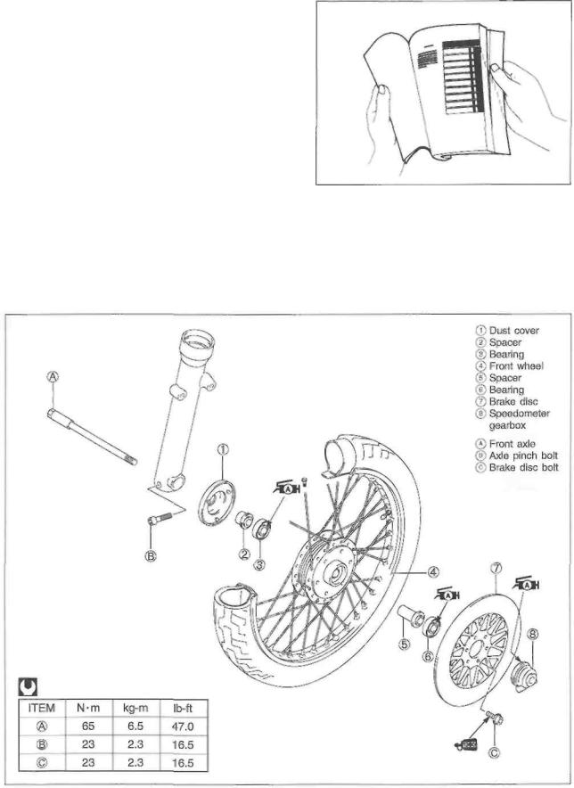
COMPONENT PARTS AND WORK TO BE DONE
Under the name of each system or unit, is its exploded view. Work instructions and other service information such as the tightening torque, lubricating points and locking agent points, are provided.
Example: Front wheel
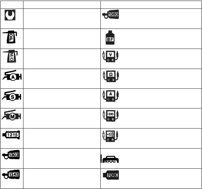
SYMBOL
Listed in the table below are the symbols indicating instructions and other information necessary for servicing. The meaning of each symbol is also included in the table.
SYMBOL |
DEFINITION |
SYMBO L |
DEFINITION |
|
Torque control required. |
|
|
|
Data beside it indicates specified |
|
Apply THREAD LOCK "1360". |
|
torque. |
|
|
Apply oil. Use engine oil unless otherwise specified.
Apply molybdenum oil solution (mixture of engine oil and SUZUKI MOLY PASTE in a ratio of 1 : 1).
99000-32130
Apply or use brake fluid.
Measure in voltage range.
Apply SUZUKI SUPER GREASE "A".
99000-25010
Apply SUZUKI SILICONE GREASE.
99000-25100
Apply SUZUKI MOLY PASTE.
99000-25140
Apply SUZUKI BOND "1215".
99000-31110
Apply THREAD LOCK SUPER "1303".
99000-32030
Measure in resistance range.
Measure in current range.
Measure in diode test range.
Measure in continuity test range.
Use special tool.
Apply THREAD LOCK "1342". |
Use fork oil. 99000- |
99000-32050 |
99001-SS8 |

GENERAL INFORMATION
----------------------------------------- CONTENTS |
----------------------------------------------1 |
WARNING/CAUTION/NOTE ............................................................... |
1- 1 |
GENERAL PRECAUTIONS ................................................................ |
1- 1 |
SUZUKI GZ250X ('99 - MODEL) ........................................................... |
1-3 |
SERIAL NUMBER LOCATION ........................................................... |
1-3 |
FUEL AND OIL RECOMMENDATIONS .............................................. |
1-3 |
FUEL ............................................................................................... |
1-3 |
ENGINE OIL ................................................................................. |
1-4 |
BRAKE FLUID .............................................................................. |
1-4 |
FRONT FORK OIL .......................................................................... |
1-4 |
BREAK - IN PROCEDURES ................................................................. |
1-4 |
INFORMATION LABELS .................................................................... |
1-5 |
SPECIFICATIONS ............................................................................. |
1-6 |
COUNTRY AND AREA CODES ........................................................ |
1-8 |

1-1 GENERAL INFORMATION
WARNING/CAUTION/NOTE
Please read this manual and follow its instructions carefully. To emphasize special information, the symbol and the words WARNING, CAUTION and NOTE have special meanings. Pay special attention to the messages highlighted by these signal words.
WARNING
Indicates a potential hazard that could result in death or injury.
CAUTION
Indicates a potential hazard that could result in motorcycle damage.
NOTE:
Indicates special information to make maintenance easier or instructions clearer.
Please note, however, that the warnings and cautions contained in this manual cannot possibly cover all potential hazards relating to the servicing, or lack of servicing, of the motorcycle. In addition to the WARNINGS and CAUTIONS stated, you must use good judgement and basic mechanical safety principles. If you are unsure about how to perform a particular service operation, ask a more experienced mechanic for advice.
GENERAL PRECAUTIONS
WARNING
Proper service and repair procedures are important for the safety of the service mechanic and the safety and reliability of the motorcycle.
When 2 or more persons work together, pay attention to the safety of each other. When it is necessary to run the engine indoors, make sure that exhaust gas is forced outdoors.
When working with toxic or flammable materials, make sure that the area you work in is well ventilated and that you follow all of the manufacturer's instructions. Never use gasoline as a cleaning solvent.
To avoid getting burned, do not touch the engine, engine oil and exhaust system until they have cooled.
After servicing fuel, oil, exhaust or brake systems, check all of the lines and fittings related to the system for leaks.

GENERAL INFORMATION 1-2
CAUTION
*If parts replacement is necessary, replace the parts with Suzuki Genuine Parts or their equivalent.
*When removing parts that are to be reused, keep them arranged in an orderly manner so that they may be reinstalled in the proper order.
*Be sure to use special tools when instructed.
*Make sure that all parts used in reassembly are clean. Lubricate them when specified.
*Use the specified lubricant, bond, or sealant.
*When removing the battery, disconnect the negative cable first and then the positive cable.
*When reconnecting the battery, connect the positive cable first and then the negative cable, and cover the positive terminal with the terminal cover.
*When performing service to electrical parts, disconnect the battery negative cable unless the service procedure requires the battery power.
*When tightening cylinder head and crankcase bolts and nuts, tighten the larger sizes first. Always tighten the bolts and nuts from the inside working out, in a crisscross pattern and to the specified tightening torque.
*Whenever you remove oil seals, gaskets, packing, O-rings, self-locking nuts, locking washers, cotter pins, circlips, and certain other parts as specified, be sure to replace them with new ones. Also, before installing these new parts, be sure to remove any left over material from the mating surfaces.
*Never reuse a circlip. When installing a new circlip, take care not to expand the end gap larger than required to slip the circlip over the shaft. After installing a circlip, always ensure that it is completely seated in its groove and securely fitted.
*Use a torque wrench to tighten fasteners to the specified torque. Wipe off grease and oil if a thread is smeared with them.
*After reassembling, check parts for tightness and proper operation.
CAUTION
*To protect the environment, do not unlawfully dispose of used motor oil and all other fluids, batteries, and tires.
*To protect the earth's natural resouces, properly dispose of used motorcycles and parts.
1-3 GENERAL INFORMATION
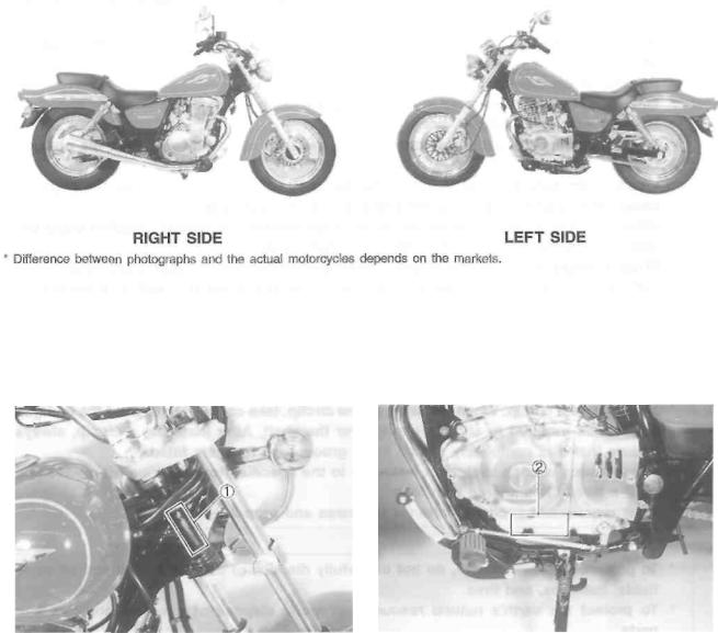
SUZUKI GZ250X ('99-MODEL)
SERIAL NUMBER LOCATION
The frame serial number or V.I.N. (Vehicle Identification Number) is stamped on the right side of the steering head pipe. The engine serial number
 is located on the left side of the crankcase. These numbers are required especially for registering the machine and ordering spare parts.
FUEL AND OIL RECOMMENDATIONS
FUEL
Use unleaded gasoline that is graded 91 octane or higher.
GENERAL INFORMATION 1-4
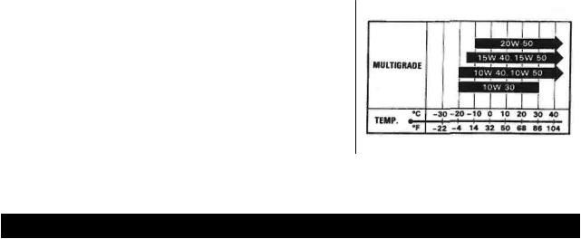
ENGINE OIL
Use only oils which are rated SF or SG under the API classification. The recommended viscosity is SAE 10W/40. If SAE 10W/40 engine oil is not available, select an alternative according to the chart.
BRAKE FLUID
 Specification and classification: DOT 4
WARNING
This motorcycle uses a glycol-based brake fluid. Do not use or mix different types of brake fluid such as silicone-based and petroleum-based fluids for refilling the system, otherwise serious damage will result to the brake system.
Never use any brake fluid taken from old, used or unsealed containers.
Never re-use brake fluid left over from a last servicing or which has been stored for a long period of time.
FRONT FORK OIL
Use SUZUKI fork oil SS-08 (#10).
BREAK-IN PROCEDURES
During manufacturing only the best possible materials are used and all machined parts are finished to a very high standard. It is still necessary to allow the moving parts to "BREAK-IN" before subjecting the engine to maximum stresses. The future performance and reliability of the engine depends on the care and restraint exercised during its early life. The general rules are as follows.
• Keep to this break-in throttle position.
Initial 800 km (500 miles) : Less than 1/2 throttle
Up to 1 600 km (1 000 miles): Less than 3/4 throttle
•Upon reaching an odometer reading of 1 600 km you can subject the motorcycle to full throttle operation for short periods of time.
GENERAL INFORMATION 1-6
SPECIFICATIONS
DIMENSIONS AND DRY MASS
Overall length ............................................. |
2 160 mm |
(85.0 in) |
Overall width ................................................ |
815 mm |
(32.1 in) |
Overall height .............................................. |
1 090 mm |
(42.9 in) |
Wheelbase .................................................... |
1 450 mm |
(57.1 in) |
Ground clearance ......................................... |
125 mm |
( 4.9 in) |
Seat height .................................................... |
680 mm |
(27.8 in) |
Dry mass ..................................................... |
137 kg (302 lbs) |
|
ENGINE
Type ..............................................................
Number of cylinder ........................................
Bore...............................................................
Stroke ...........................................................
Displacement ................................................
Compression ratio .........................................
Carburetor ...................................................
Air cleaner .....................................................
Starter system ...............................................
Lubrication system .......................................
Four-stroke, air-cooled, OHC
1
72.0 mm (2.835 in)
61.2 mm (2.409 in)
249 cm3 (15.2 cu. in)
9.0 : 1
MIKUNI BSR32SS, single Non-woven fabric element Electric
Wet sump
TRANSMISSION
Clutch ...........................................................
Transmission ...............................................
Gearshift pattern............................................
Primary reduction ratio ...............................
Final reduction ratio......................................
Gear ratios, Low .........................................
2nd ........................................
3rd..........................................
4th ..........................................
Top .......................................
Drive chain ...................................................
Wet multi-plate type 5-speed constant mesh 1-down, 4-up
3.238 (68/21)
2.733 (41/15)
2.636 (29/11)
1.687 (27/16)
1.263 (24/19)
1.000 (20/20)
0.818 (18/22)
DID 520VC5, 110 links
1-7 GENERAL INFORMATION
ELECTRICAL
Ignition type .............................................................. |
Electronic ignition (Transistorized) |
||
Ignition timing ........................................................ |
10° B.T.D.C. at 1 300 r/min |
||
Spark plug .............................................................. |
NGK DR8EA or DENSO X24ESR-U |
||
Battery ...................................................................... |
12V |
21.6 kC (6 Ah)/10 HR |
|
Generator ................................................................. |
Three-phase A.C. generator |
||
Fuse ......................................................................... |
20/15/15/15/10/10A |
||
Headlight .................................................................. |
12V |
60/55W |
|
Position light .......................................................... |
12V |
4W ....... |
Except for E-03, -24, -28, -33 |
Brake light/Taillight .................................................. |
12V |
21/5W |
|
Front turn signal light/Running light.......................... |
12V |
21/5W ....... |
E-03, -28, -33 |
Turn signal light ..................................................... |
12V |
21W |
|
Speedometer light .................................................... |
12V |
1.7W |
|
Neutral indicator light................................................ |
12V |
3.4W |
|
Turn signal indicator light ......................................... |
12V |
3.4W |
|
High beam indicator light ........................................ |
12V |
1.7W |
|
CHASSIS
Front suspension ................................................... |
Telescopic, coil spring, oil damped |
Rear suspension ...................................................... |
Swingarm type, coil spring, oil damped, spring |
|
preload 5-way adjustable |
Front fork stroke ....................................................... |
120 mm (4.7 in) |
Rear wheel travel ..................................................... |
90 mm (3.5 in) |
Steering angle .......................................................... |
40° (right and left) |
Caster ...................................................................... |
32° 30' |
Trail ......................................................................... |
140 mm (5.5 in) |
Turning radius .......................................................... |
2.6 m (8.5 ft) |
Front brake ............................................................... |
Disc brake |
Rear brake................................................................ |
Internal expanding |
Front tire size .......................................................... |
110/90-16 59P |
Rear tire size ............................................................ |
130/90-15M/C 66P |
CAPACITIES
Fuel tank, including reserve ..................................... |
14 L (3.7/3.1 US/Imp gal) |
reserve ................................................ |
2.9 L (0.8/0.6 US/Imp gal) |
Engine oil, oil change ........................................... |
1 300 ml (1.4/1.1 US/Imp qt) |
with filter change ................................ |
1 400 ml (1.5/1.2 US/Imp qt) |
overhaul ............................................. |
1 700 ml (1.8/1.5 US/Imp qt) |
Front fork oil (each leg) ......................................... |
369 ml (12.5/13.0 US/Imp oz) |
Specifications are subject to change without notice. |
|

GENERAL INFORMATION 1-8
COUNTRY AND AREA CODES
The following codes stand for the applicable country(-ies) and area(-s).
CODE |
COUNTRY OR AREA |
E-01 |
General |
E-02 |
UK |
E-03 |
U.S.A. (Except for California) |
E-04 |
France |
E-17 |
Sweden, Finland (E-15), Norway (E-16), Denmark (E-26) |
E-22 |
Germany |
E-24 |
Australia |
E-25 |
Netherlands |
E-28 |
Canada |
E-33 |
California (U.S.A.) |
E-34 |
Italy, Belgium (E-21), Spain (E-53) |

PERIODIC MAINTENANCE
----------------------------------------- CONTENTS ------------------------------------------ |
|
PERIODIC MAINTENANCE SCHEDULE ............................................. |
2- 1 |
PERIODIC MAINTENANCE CHART ................................................ |
2- 1 |
LUBRICATION POINTS ................................................................. |
2-2 |
MAINTENANCE AND TUNE - UP PROCEDURES .............................. |
2-3 |
EXHAUST PIPE BOLTS AND MUFFLER MOUNTING BOLTS ......... |
2-3 |
AIR CLEANER ................................................................................ |
2- 3 |
VALVE CLEARANCE ..................................................................... |
2-4 |
SPARK PLUG ................................................................................. |
2- 6 |
FUEL HOSE .................................................................................... |
2- 7 |
ENGINE IDLE SPEED ..................................................................... |
2- 7 |
THROTTLE CABLE PLAY ............................................................... |
2- 7 |
STARTER PLUNGER CABLE PLAY ............................................... |
2-9 |
CLUTCH .......................................................................................... |
2-9 |
ENGINE OIL AND OIL FILTER ........................................................ |
2- 9 |
DRIVE CHAIN .................................................................................. |
2-70 |
BRAKES .......................................................................................... |
2-12 |
TIRE ............................................................................................... |
2-15 |
STEERING ....................................................................................... |
2-15 |
FRONT FORK ................................................................................. |
2-16 |
REAR SUSPENSION ....................................................................... |
2-16 |
CHASSIS BOLTS AND NUTS ......................................................... |
2-16 |
COMPRESSION PRESSURE CHECK ............................................... |
2-18 |
OIL PRESSURE CHECK .................................................................... |
2-19 |

2-1 PERIODIC MAINTENANCE
PERIODIC MAINTENANCE SCHEDULE
The chart below lists the recommended intervals for all the required periodic service work necessary to keep the motorcycle operating at peak performance and economy. Maintenance intervals are expressed in terms of kilometers and months, and are dependant on whichever comes first.
NOTE:
More frequent servicing may be performed on motorcycles that are used under severe conditions.
PERIODIC MAINTENANCE CHART
Interval
Item
Exhaust pipe bolts and muffler mounting Air cleaner element
Valve clearance Spark plug Fuel hose
Engine idle speed
Throttle cable play
Clutch
Engine oil
Engine oil filter
Drive chain
Brakes
Brake hose
Brake fluid
Tires
Steering
Front fork
Rear suspension
Chassis bolts and nuts
km |
1 000 |
5 000 |
10 000 |
15 000 |
miles |
600 |
3 000 |
6 000 |
9 500 |
months |
3 |
15 |
30 |
45 |
bolts |
- |
T |
T |
T |
|
Clean every 3 000 km (2 000 miles). |
|||
|
I |
I |
I |
I |
|
- |
I |
R |
I |
|
- |
I |
I |
I |
|
|
Replace every 4 years. |
|
|
|
I |
I |
I |
I |
|
I |
I |
I |
I |
|
- |
I |
I |
I |
|
R |
R |
R |
R |
|
R |
- |
R |
- |
|
I |
I |
I |
I |
|
Clean and lubricate every 1 000 km (600 miles). |
|||
|
I |
I |
I |
I |
|
- |
I |
I |
I |
|
|
Replace every 4 years. |
|
|
|
- |
I |
I |
I |
|
|
Replace every 2 years. |
|
|
|
- |
I |
I |
I |
|
I |
- |
I |
- |
|
- |
- |
I |
- |
|
- |
- |
I |
- |
|
T |
T |
T |
T |
NOTE:
I: Inspection and adjust, clean, lubricate or replace as necessary C: Clean R: Replace T: Tighten

PERIODIC MAINTENANCE 2-2
LUBRICATION POINTS
Proper lubrication is important for smooth operation and long life of each working part of the motorcycle. Major lubrication points are indicated below.
Side-stand pivot |
Drive chain |
and spring hook |
|
|
Brake pedal pivot |
Clutch |
Brake lever holder |
NOTE:
*Before lubricating each part, clean off any rusty spots and wipe off any grease, oil, dirt or grime.
*Lubricate exposed parts which are subject to rust, with a rust preventative spray especially whenever the motorcycle has been operated under wet or rainy condition.

2-3 PERIODIC MAINTENANCE
MAINTENANCE AND TUNE-UP PROCEDURES
This section describes the servicing procedures for each item in the Periodic Maintenance chart.
EXHAUST PIPE BOLTS AND MUFFLER
MOUNTING BOLTS
Tighten every 5 000 km (3 000 miles, 15 months).
•Tighten the exhaust pipe bolts and muffler mounting
bolt to the specified torque.
Exhaust pipe bolt : 14 N ■ m (1.4 kg-m, 10.0 Ib-ft) Muffler mounting bolt
 : 29 N ■ m (2.9 kg-m, 21.0 Ib-ft)
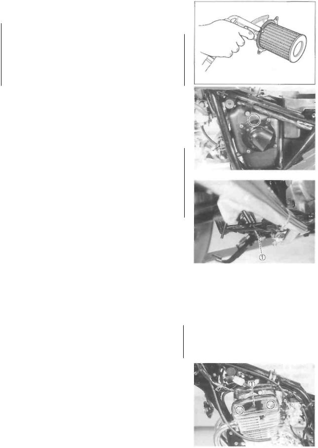
AIR CLEANER
Clean every 3 000 km (2 000 miles).
If the air cleaner is clogged with dust, intake resistance will increase, resulting in a decrease in engine output and an increase in fuel consumption. Check and clean the air cleaner element in the following manner.
•Remove the front seat. (See p. 5-1.)
•Remove the left frame cover. (See p. 5-1.)
•Remove the air cleaner element  .
.
PERIODIC MAINTENANCE 2-4
•Carefully use compressed air to clean the air cleaner element.
CAUTION CAUTION ________________________________
Always apply compressed air to the outside of the air cleaner element. If compressed air is applied to the inside, dirt will be forced into the pores of the air cleaner element, restricting air flow through the air cleaner element.
•Reinstall the cleaned or new air cleaner element in the reverse order of removal.
•When installing the air cleaner element into the air cleaner case, align the triangle marks on the air cleaner element and the air cleaner case.
CAUTION
If driving under dusty conditions, clean the air cleaner element more frequently. The surest way to accelerate engine wear is to operate the engine without the element or to use a torn element. Make sure that the air cleaner is in good condition at all times. The life of the engine depends largely on this component!
NOTE:
When cleaning the air cleaner element, remove the plug and drain any water from the air cleaner drain hose.
VALVE CLEARANCE
Inspect initially at 1 000 km (600 miles, 3 months) and every 5 000 km (3 000 miles, 15 months) thereafter.
INSPECTION
•Remove the front seat. (See p. 5-1.)
•Remove the fuel tank. (See p. 4-1.)
•Remove the cylinder head cover left cap
•Disconnect the spark plug cap and remove the spark plug.
 09930-10121: Spark plug socket wrench set

2-5 PERIODIC MAINTENANCE
Remove the valve inspection caps
The valve clearance specification is different for intake and exhaust valves.
Valve clearance adjustment must be checked and adjusted, 1) at the time of periodic inspection, 2) when the valve mechanism is serviced, and 3) when the camshaft is removed for servicing.
Valve clearance (when cold):
IN. : 0.03-0.08 mm (0.001-0.003 in)
EX.: 0.08-0.13 mm (0.003-0.005 in)
NOTE:
*The piston must be at top dead center (TDC) on the compression stroke in order to check or adjust the valve clearance.
*The valve clearance should only be checked when the engine is cold.
*Remove the valve timing inspection plug and generator cover cap
Rotate the crankshaft with a box wrench to set the piston at top dead center (TDC) on the compression stroke. (Rotate the crankshaft until the "T" line on the generator rotor is aligned with the triangle mark
 on the generator cover.)
Insert a thickness gauge into the clearance between the valve stem end and the adjusting screw on the rocker arm.
09900-20803: Thickness gauge
If the clearance is out of specification, adjust it to specification as follows.
PERIODIC MAINTENANCE 2-6
ADJUSTMENT
The clearance is adjusted using the special tool and offset wrench.
•Loosen the locknuts
•Insert a thickness gauge between the valve stem end and the adjusting screw on the rocker arm.
•Adjust the valve clearance by turning the adjusting screw  using the special tool while holding the locknuts
 09917-14920: Valve adjuster wrench
CAUTION
Both the right and left valve clearances should be as closely as possible.
•After the adjustment is completed, tighten the locknut securely.
•Rotate the crankshaft 720° with a box wrench and check that the clearance is within specification.
SPARK PLUG
Inspect every 5 000 km (3 000 miles, 15 months).
Replace every 10 000 km (6 000 miles, 30 months).
Neglecting the spark plug eventually leads to difficult starting and poor engine performance. If the spark plug is used for a long period, the electrode gradually bums away and carbon builds up along the inside part of the spark plug. In accordance with the Periodic Maintenance chart, the spark plug should be inspected, cleaned and regapped at the recommended intervals.
•Remove the cylinder head cover left cap.
•Disconnect the spark plug cap and remove the spark plug.
 09930-10121: Spark plug socket wrench set
• Carbon deposits on the spark plug will prevent good
sparking and may cause the engine to misfire. Be sure to clean the carbon deposits off periodically.
If the center electrode is fairly worn down, the spark plug should be replaced and the spark plug gap set to the specification using a thickness gauge.
09900-20803: Thickness gauge
Spark plug gap: 0.6-0.7 mm (0.024-0.028 in)

2-7 PERIODICMAINTENANCE
Check the spark plug for burns. If any abnormalities are found, replace the spark plug as indicated below.
NGK |
DENSO |
DR7EA |
X22ESR-U |
DR8EA |
X24ESR-U |
DR9EA |
X27ESR-U |
Remarks
If the standard spark plug is apt to get wet, replace with this plug.
 Standard
If the standard spark plug is apt to overheat, replace with this plug.
CAUTION
Confirm the thread size and reach when replacing the spark plug. If the reach is too short, carbon will be deposited on the screw portion of the plug hole and engine damage may result.
CAUTION
Before using a spark plug wrench, carefully turn the spark plug by finger into the threads of the cylinder head to prevent damage.
•Tighten the spark plug to the specified torque using the special tool.
 Spark plug: 18 N-m (1.8 kg-m, 13.0 Ib-ft)
  09930-10121: Spark plug socket wrench set
FUEL HOSE
Inspect every 5 000 km (3 000 miles, 15 months). Replace every 4 years.
ENGINE IDLE SPEED
Inspect initially at 1 000 km (600 miles, 3 months) and every 5 000 km (3 000 miles, 15 months) thereafter.
•Adjust the throttle cable play. (See p. 2-8.)
•Warm up the engine.
NOTE:
Make this adjustment when the engine is hot.
• Connect an electric tachometer to the high tension cord.
PERIODIC MAINTENANCE 2-8
•Start the engine, turn the throttle stop screw and set the engine idle speed as follows.
Engine idle speed: |
|
1 300 ± 50 r/min .... |
For E-03, -28, -33 |
1 300 ±100 r/min..... |
For the others |
 09900-26006: Tachometer
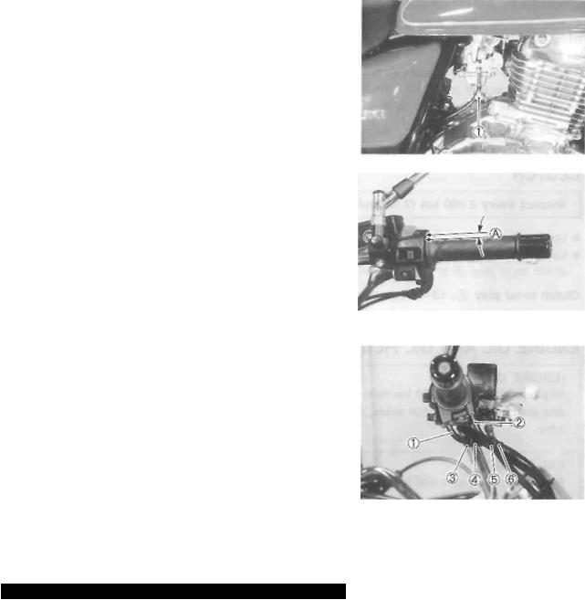
THROTTLE CABLE PLAY
Inspect initially at 1 000 km (600 miles, 3 months) and every 5 000 km (3 000 miles, 15 months) thereafter.
Adjust the throttle cable play  with the following three steps.
First step:
•Loosen the lock nut of the throttle returning cable
 and turn in the adjuster
 fully into the threads.
Second step:
•Loosen the lock nut of the throttle pulling cable
•Turn the adjuster in or out until the throttle cable play
 should be 2.0-4.0 mm (0.08-0.16 in) at the throttle grip.
•Tighten the lock nut  while holding the adjuster
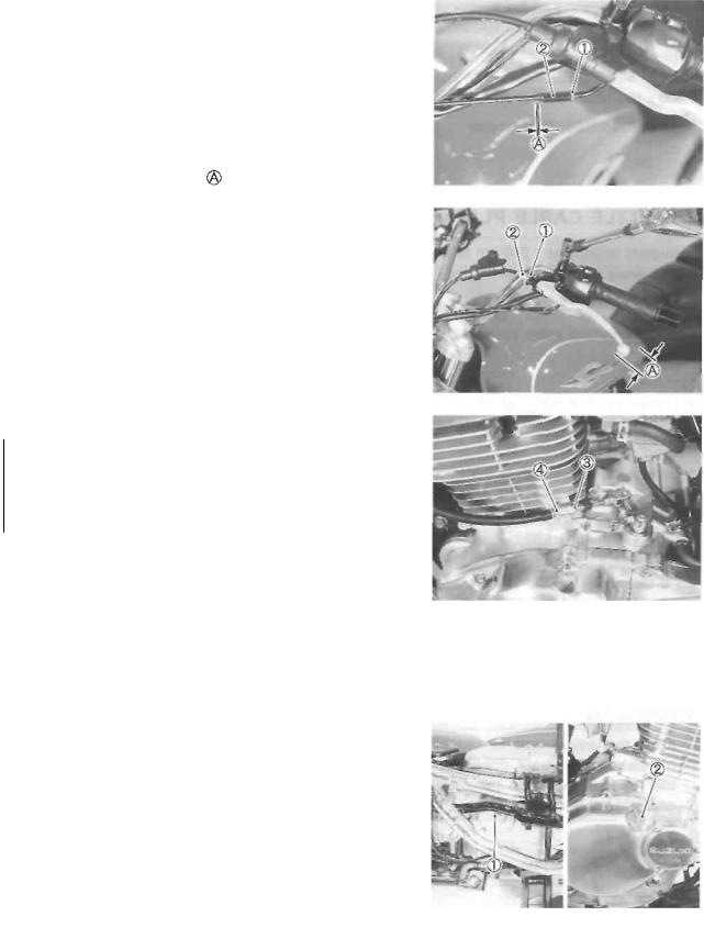
Third step:
•While holding the throttle grip at the fully closed position,
slowly turn out the adjuster  of the throttle returning cable
  to feel resistance.
•Tighten the lock nut while holding the adjuster
Throttle cable play : 2.0-4.0 mm (0.08-0.16 in)
WARNING
After the adjustment is completed, check that handlebar movement does not raise the engine idle speed and that the throttle grip returns smoothly and automatically.
NOTE:
Major adjustment can be made by the carburetor side adjuster.
2-9 PERIODICMAINTENANCE
STARTER PLUNGER CABLE PLAY
Starter plunger cable play  should be 0.5-1.0 mm (0.02-0.04 in) as shown. If the play
 is incorrect, adjust it as follows:
•Loosen the lock nut and turn the adjuster
 in or out until the specified play is obtained.
•Tighten the lock nut while holding the adjuster
Starter plunger cable play |
0.5-1.0 mm |
|
(0.02-0.04 in) |
CLUTCH
Inspect every 5 000 km (3 000 miles, 15 months).
•Loosen the lock nut and turn the adjuster
 fully in.
•Loosen the lock nut and turn the adjuster
 until the clutch lever play
 is within specification.
Clutch lever play : 10-15 mm (0.4-0.6 in)
• Tighten the lock nuts
ENGINE OIL AND OIL FILTER
(ENGINE OIL)
Replace initially at 1 000 km (600 miles, 3 months) and every 5 000 km (3 000 miles, 15 months) thereafter.
(OIL FILTER)
Replace initially at 1 000 km (600 miles, 3 months) and every 10 000 km (6 000 miles, 30 months) thereafter.
The engine oil should be changed while the engine is warm. Oil filter replacement at the above intervals should be done together with the engine oil change.
ENGINE OIL REPLACEMENT
•Keep the motorcycle upright.
•Place an oil pan below the engine, and drain the engine
oil by removing the engine oil drain plug and oil filler cap
 .
.
•Tighten the oil drain plug to the specified torque, and pour new oil through the oil filler. When performing an oil change (without oil filter replacement), the engine will hold about 1 300 ml (1.4/1.1 US/Imp qt) of oil. Use SF or SG classified (API) engine oil with a viscosity rating of 10W-40 (SAE).
 Oil drain plug: 28 N-m (2.8 kg-m, 20.0 Ib-ft)
• Install the oil filler cap
PERIODIC MAINTENANCE 2-10
•Start up the engine and allow it to run for a few minutes at idling speed.
•Turn off the engine and wait about one minute, then
check the oil level through the inspection window  . If the level is below the "F" mark, add oil to the proper level.
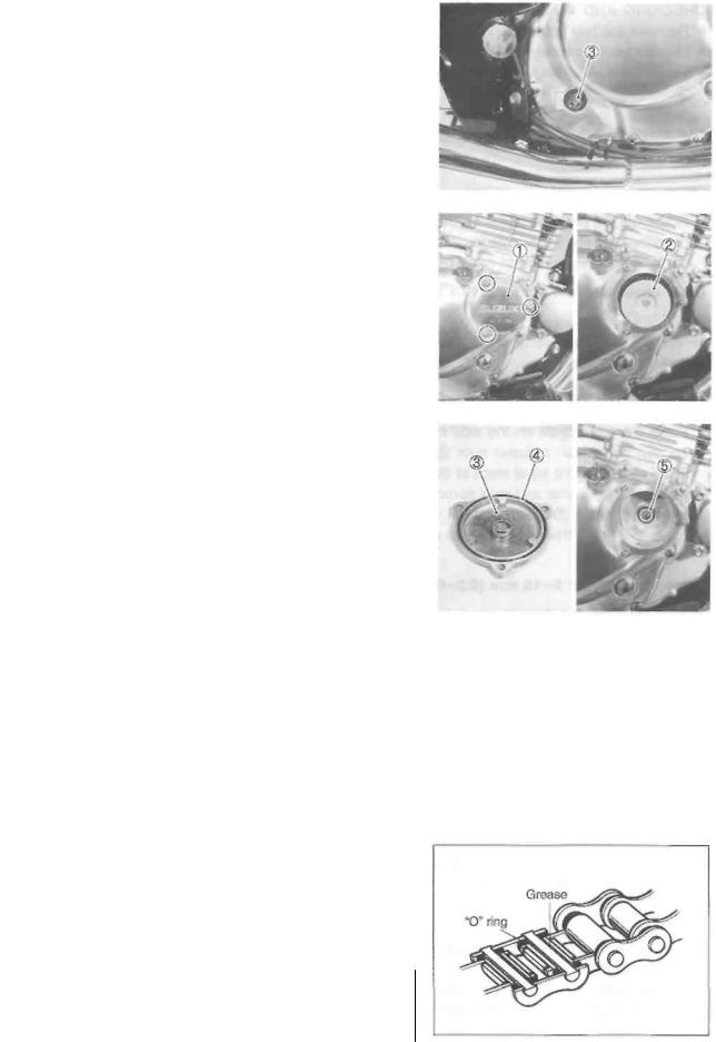
OIL FILTER REPLACEMENT
•Drain the engine oil as described in the engine oil replacement procedure.
•Remove the oil filter cap by removing the nuts.
•Remove the oil filter and install a new one.
•Install the oil filter cap  and tighten the nuts securely.
NOTE:
Before installing the new oil filter and oil filter cap, make sure that the spring  and new O-rings
  are installed correctly.
•Add new engine oil and check the oil level as described in the engine oil replacement procedure.
Oil viscosity and classification:
10W/40 (SAE)/SF or SG (API)
NECESSARY AMOUNT OF ENGINE OIL
Oil change : 1 300 ml (1.4/1.1 US/Imp qt)
Oil and filter change: 1 400 ml (1.5/1.2 US/Imp qt)
Engine overhaul : 1 700 ml (1.8/1.5 US/Imp qt)
DRIVE CHAIN
Inspect initially at 1 000 km (600 miles, 3 months) and every 5 000 km (3 000 miles, 15 months) thereafter. Clean and lubricate every 1 000 km (600 miles).
Visually inspect the drive chain for the possible defects listed below. (Support the motorcycle by a jack and a wooden block, turn the rear wheel slowly by hand with the transmission shifted to Neutral.)
• |
Loose pins |
* |
Excessive wear |
• |
Damaged rollers |
* |
Kinked or binding links |
• Dry or rusted links |
* |
Missing O-ring seals |
|
• Twisted or seized links |
|
|
|
If any defects are found, the drive chain must be replaced.
The standard drive chain is DID520VC5. SUZUKI recommends to use this standard drive chain as a replacement.
CAUTION __________________________________
The standard drive chain is DID520VC5. SUZUKI
replacement.
2-11 PERIODICMAINTENANCE
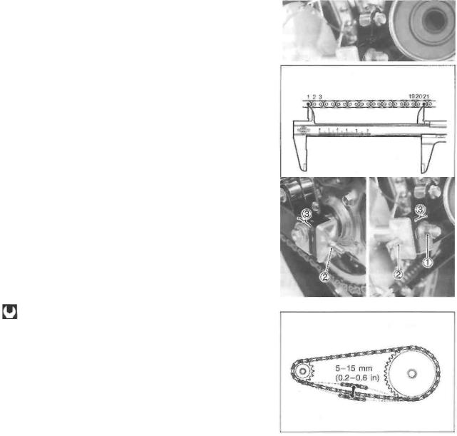
CHECKING AND ADJUSTING
•Remove the rear axle cotter pin. (For E-28 model)
•Loosen the rear axle nut
•Tense the drive chain fully by turning chain adjuster nuts
•Count out 21 pins (20-pitch) on the chain measure the distance between the two points. If the distance exceeds the service limit, the chain must be replaced.
Drive chain 20-pitch length: 319.4 mm (12.57 in)
NOTE:
When replacing the drive chain, replace the drive chain and sprockets as a set.
•Place the motorcycle on the side-stand.
•Loosen both chain adjuster nuts  until the chain has 5-15 mm (0.2-0.6 in) of slack at the middle of the chain between
the engine and rear sprockets as shown. The reference marks must be at the same position on the scale to ensure that the front and rear wheels are correctly aligned.
Drive chain slack: 5-15 mm (0.2-0.6 in)
•After adjusting the drive chain, tighten the rear axle nut  to the specified torque.
Rear axle nut: |
|
65 N-m (6.5 kg-m, 47.0 Ib-ft)........ |
For E-03, -28, -33 |
78N-m (7.8 kg-m, 56.5 Ib-ft) ........ For the others
•Recheck the chain slack after tightening the axle nut and readjust if necessary.
* Tighten both chain adjuster nuts securely.
• Install the new cotter pin. (For E-03, -28, -33 models)
CLEANING AND LUBRICATING
•Clean the drive chain with kerosine. If the drive chain tends to rust quickly, the intervals must be shortened.
CAUTION
Do not use trichloroethylene, gasoline or any similar solvent.
These fluids have too great a dissolving power for this chain and they can damage the O-rings. Use only kerosine to clean the drive chain.

PERIODIC MAINTENANCE 2-12
•After cleaning and drying the chain, oil it with a heavyweight engine oil.
CAUTION
Do not use any oil sold commercially as "drive chain oil", this type of oil can such oil can damage the "0"-rings (or seals).
BRAKES
(BRAKE)
Inspect initially at 1 000 km (600 miles, 3 months) and every 5 000 km (3 000 miles, 15 months) thereafter.
(BRAKE HOSE AND BRAKE FLUID)
Inspect every 5 000 km (3 000 miles, 15 months). Replace hose every 4 years. Replace fluid every 2 years.
BRAKE FLUID LEVEL
•Keep the motorcycle upright and place the handlebars straight.
•Check the brake fluid level by observing the lower limit line on the front brake fluid reservoir.
•When the brake fluid level is below the lower limit line replenish with brake fluid that meets the following specification.
 Specification and classification: DOT 4
WARNING
The brake system of this motorcycle is filled with a glycol-based brake fluid. Do not use or mix different types of fluid such as siliconebased and petroleum-based fluids. Do not use any brake fluid taken from old, used or unsealed containers. Never re-use brake fluid left over from the last servicing or stored for a long period of time.
Brake fluid, if it leaks, will interfere with safe running and immediately discolor painted surfaces. Check the brake hose and hose joints for cracks and oil leakage.

2-13 PERIODICMAINTENANCE
FRONT BRAKE PADS
The extent of brake pad wear can be checked by observing the limit line on the pad. When the wear exceeds the limit line, replace the pads with new ones. (See p. 5-8.)
A CAUTION
Replace the brake pad as a set, otherwise braking performance will be adversely affected.
AIR BLEEDING THE BRAKE FLUID CIRCUIT
Air trapped in the brake fluid circuit acts like a cushion to absorb a large proportion of the pressure developed by the master cylinder and thus interferes with the full braking performance of the brake caliper. The presence of air is indicated by "sponginess" of the brake lever and also by lack of braking force. Considering the danger to which such trapped air exposes the machine and rider, it is essential that, after remounting the brake and restoring the brake system to the normal condition, the brake fluid circuit be purged of air in the following manner:
•Fill the master cylinder reservoir to top of the inspection window. Replace the reservoir cap to prevent dirt from entering.
•Attach a hose to the air bleeder valve, and insert the free end of the hose into a receptacle.
•Bleed air from the brake system.
•Squeeze and release the brake lever several times in rapid succession and squeeze the lever fully without releasing it. Loosen the bleeder valve by turning it a quarter of a turn so that the brake fluid runs into the receptacle, this will remove the tension of the brake lever causing it to touch the handlebar grip. Then, close the air bleeder valve, pump and squeeze the brake lever, and open the valve. Repeat this process until the fluid flowing into the receptacle no longer contains air bubbles.
NOTE:
While bleeding the brake system, replenish the brake fluid in the reservoir as necessary. Make sure that there is always some fluid visible in the reservoir.
•Close the air bleeder valve, and disconnect the hose. Fill the reservoir with brake fluid to the top of the inspection window.
 Air bleeder valve: 7.5 N ■ m (0.75 kg-m, 5.5 Ib-ft)
A CAUTION
Handle brake fluid with care: the fluid reacts chemically with paint, plastics, rubber materials, etc.

REAR BRAKE PEDAL HEIGHT
•Loosen the lock nut
•Adjust the brake pedal height by turning the adjuster
  to locate the pedal 50 mm (2.0 in) above the top face of the footrest.
REAR BRAKE ADJUSTING
•Adjust the free travel to 20-30 mm (0.8-1.2 in) by turning the adjusting nut
REAR BRAKE SHOE WEAR
This motorcycle is equipped with brake lining wear limit indicator on the rear brake.
To check brake lining wear, perform the following steps.
•Make sure that the rear brake is properly adjusted.
•Depress the rear brake pedal. Make sure that the index
mark is within the range
 embossed on the brake panel.
•If the index mark goes beyond the range, the brake shoe assembly should be replaced with a new set of shoes.
BRAKE LIGHT SWITCH
Adjust the rear brake light switch so that the brake light will come on just before pressure is felt when the brake pedal is depressed.
PERIODIC MAINTENANCE 2-14
The extension line of the index mark is within the range.
The extension line of the index mark is out of the ranae.
 Loading...