


RM250

RM250
OWNER’S SERVICE MANUAL
Part No. 99011-37F56-01A
May, 2006 EN
TK

This manual should be considered a permanent part of
the motorcycle and should remain with the motorcycle
when resold or otherwise transferred to a new owner or
operator.
The manual contains important safety information and
instructions which should be read carefully before
operating the motorcycle.

FOREWORD
This manual is presented as a means whereby you
can maintain your RM250 in top working condition
at all times. Your riding skill and the maintenance
steps outlined in this manual will assure you of top
performance from your machine under any type of
competition.
We sincerely wish you and your Suzuki motorcycle
a successful partnership for many years of happy
riding.
All information, illustrations, photographs and specifications contained in the manual are based on the
latest product information available at the time of
publication. Due to improvements or other changes,
there may be some discrepancies in this manual.
Suzuki reserves the right to make production
changes at any time, without notice and without
incurring any obligation to make the same or similar
changes to vehicles previous built or sold.
WARNING/CAUTION/NOTE
Please read this manual and follow its instructions
carefully. To emphasize special information, the
symbol and the words WARNING, CAUTION
and NOTE have special meanings. Pay special
attention to the messages highlighted by these signal words:
WARNING
Indicates a potential hazard that could
result in death or injury.
CAUTION
Indicates a potential hazard that could
result in motorcycle damage.
NOTE:
Indicates special information to make maintenance
easier or instructions clearer.
Suzuki Motor Corporation believes in conservation
and protection of Earth’s natural resources. To that
end, we encourage every vehicle owner to recycle,
trade in, or properly dispose of, as appropriate,
used motor oil, engine coolant, and other fluid, and
tires.
c COPYRIGHT SUZUKI MOTOR CORPORATION 2006

GENERAL CONSIDERATIONS
• Wear a helmet and goggles
A helmet is the most important piece of gear to
wear. Helmets do not reduce essential vision or
hearing. Generally, helmets do not cause or
intensify injury if you crash. Helmets simply help
your skull protect your intelligence, your memory,
your personality, and your life.
Your eyesight is equally valuable. Wearing suitable eye protection can help keep your vision
unblurred by the wind and help shield your eyes
from branches and airborne matter like bugs, dirt,
or pebbles kicked up by tires. Wear a helmet and
eye protection every time you ride.
• Practice on level ground
Before you begin riding, you should find a good
place to practice the skills you need to ride
safely. Find a flat, open area with enough space
to maneuver. Check with your Suzuki dealer or
call police department if you do not know where
you can ride.
Review the controls on your motorcycle before
riding.
• Know your limits
Always ride within the boundaries of your own
skills. Knowing these limits and staying within
them will help you avoid accidents. Ride only in
events appropriate for your experience.
• Wear protective gear
Wear proper clothing when you ride. Avoid loose
clothes or scarves, which could get caught in
moving parts. Abrasion injuries can be minimized
by wearing protective clothing including gloves,
strong boots that fit over the ankle, long pants,
and a long sleeve shirt or jackets. Experienced
riders often wear a kidney belt and chest or back
protector for additional comfort and protection.
• Inspect your machine before riding
Before each use, perform an inspection per “Periodic Inspection” section starting on page 2-3.
• No Passengers
Suzuki RMs are designed for the rider only.
Safely competing on a motorcycle requires that
your mental and physical skills are fully part of
the experience. You should not attempt to operate a motor vehicle, especially one with two
wheels, if you are tired or under the influence of
alcohol or other drugs. Alcohol, illegal drugs, and
even some prescription and over-the-counter
drugs and cause drowsiness, loss of coordination, loss of balance, and loss of good judgement. If you are tired or under the influence of
alcohol or other drugs, PLEASE DO NOT RIDE
your motorcycle.
• Conclusion
The actions of other riders are unpredictable.
Your motorcyclee’s condition can change. These
factors can best be dealt with by giving every ride
your full attention.
Circumstances beyond your control could lead to
an accident. You need to prepare for the unexpected by wearing a helmet and other protective
gear, and practicing safe riding techniques to
minimize the damage to you and your machine.
May all of your rides on your new Suzuki be winning
rides!
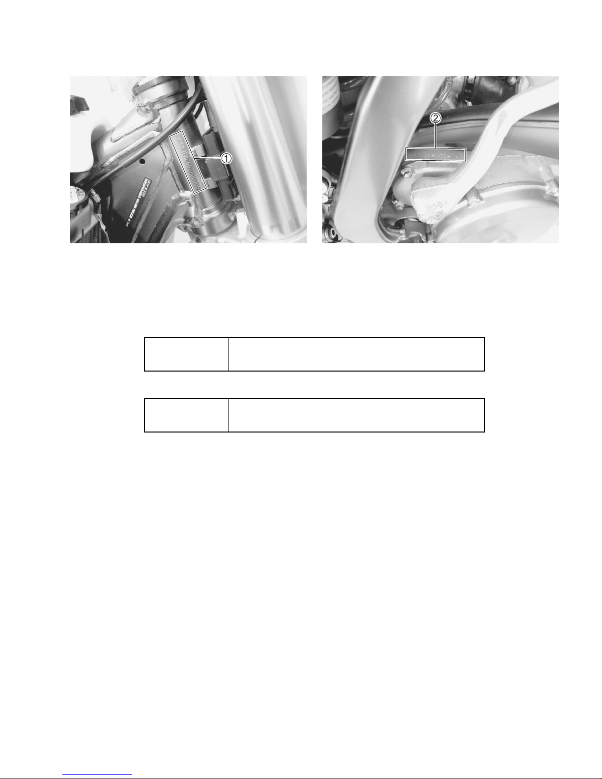
SERIAL NUMBER LOCATION
The frame number 1 is stamped on the steering head as shown in the photograph. The engine serial number 2 is stamped on the right side of the crankcase assembly.
Write down the serial numbers here for your future reference.
Frame No.
Engine No.
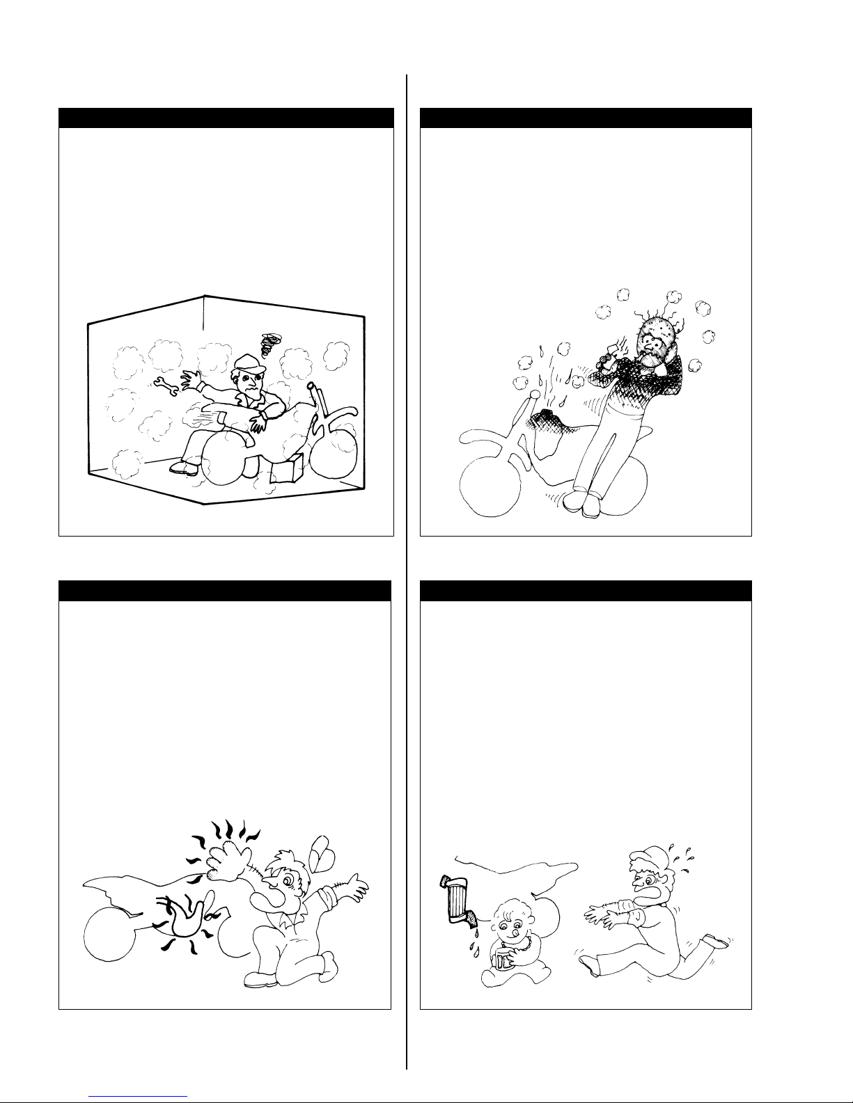
WARNINGS FOR SERVICING
WARNING
Never run the engine indoors or in a
garage. Exhaust gas contains carbon monoxide, a gas that is colorless and odorless
and can cause death or severe injury.
Only run the engine outdoors where there
is fresh air.
WARNING
Fuel can catch on fire if you do not handle
it properly. Gasoline vapors can catch fire
easily.
Do not smoke when servicing the machine.
Do not service the machine in an area
where there are open flames or sparks.
WARNING
Hot engine and muffler can burn you.
Wait until the engine and muffler cools
before servicing.
WARNING
Brake fluids and engine coolant can be
hazardous to humans and pets. Brake fluid
and engine coolant are harmful or fatal if
swallowed, and harmful if it comes in contact with your skin or eyes.
Keep brake fluid and engine coolant away
from children. Call your doctor immediately if swallowed, and induce vomiting.
Flush eyes or skin with water if either
brake fluid or engine coolant gets in eyes
or comes in contact with skin.
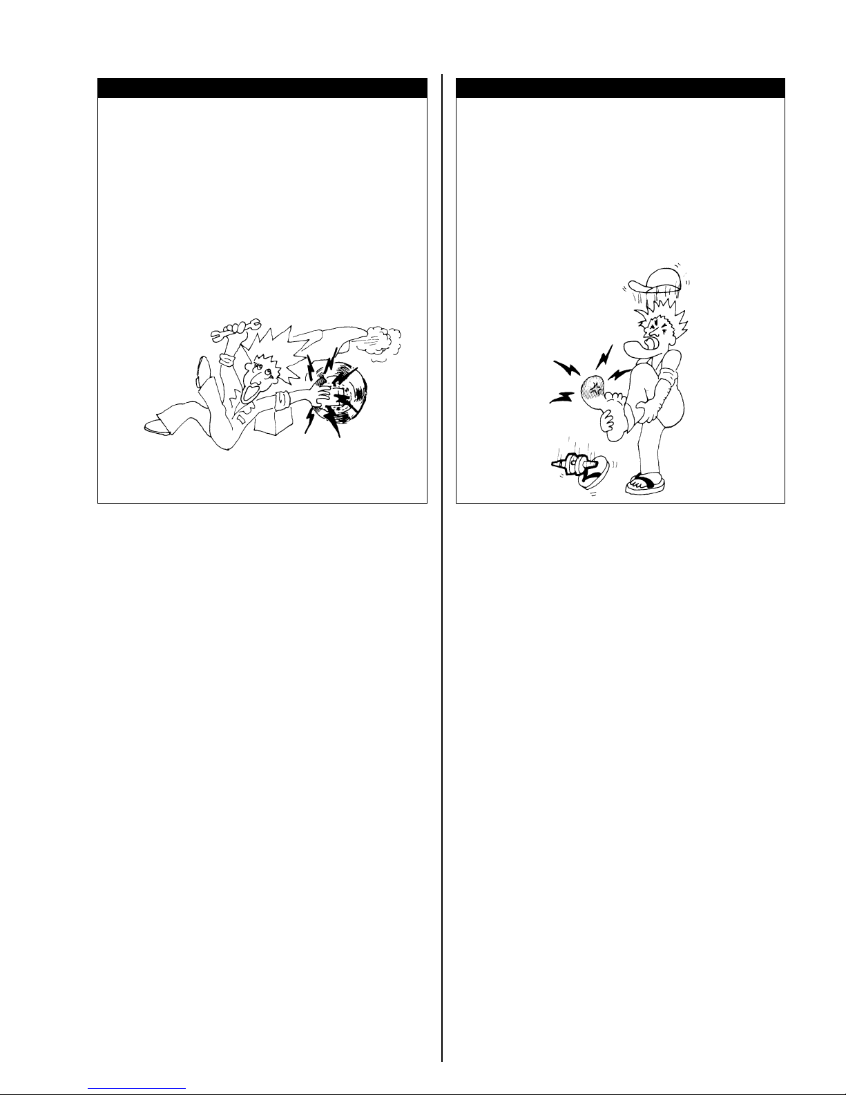
WARNING
WARNING
Servicing the machine with engine running
can be hazardous. You can be caught in
the moving parts such as the drive chain,
sprockets etc.
Be sure to stop the engine when servicing
the machine.
Servicing the machine without proper
clothes and protective gear can be hazardous. You can be injured if you do not wear
proper clothes and protective gear.
Be sure to wear proper clothes and shoes
for servicing and wear protective glasses,
mask or gloves as necessary.
PRECAUTIONS FOR SERVICING
• Replace gaskets, snap rings, circlips, O-rings
and cotter pins with new ones.
• Take care not to expand the end gap larger than
required to slip the circlip over the shaft when
installing a circlip.
• Use special tools where specified.
• Use genuine SUZUKI parts and recommended
oil.
• When two or more persons work together, pay
attention to the safety of each other.
• After reassembly, inspect parts for tightness and
operation.
REPLACEMENT PARTS
Use only genuine SUZUKI replacement parts or
their equivalent. Genuine SUZUKI parts are high
quality parts which are designed and built specially
for SUZUKI vehicles.
NOTE:
Use of replacement parts which are not equivalent
in quality to genuine SUZUKI parts can lead to performance problems and damage.
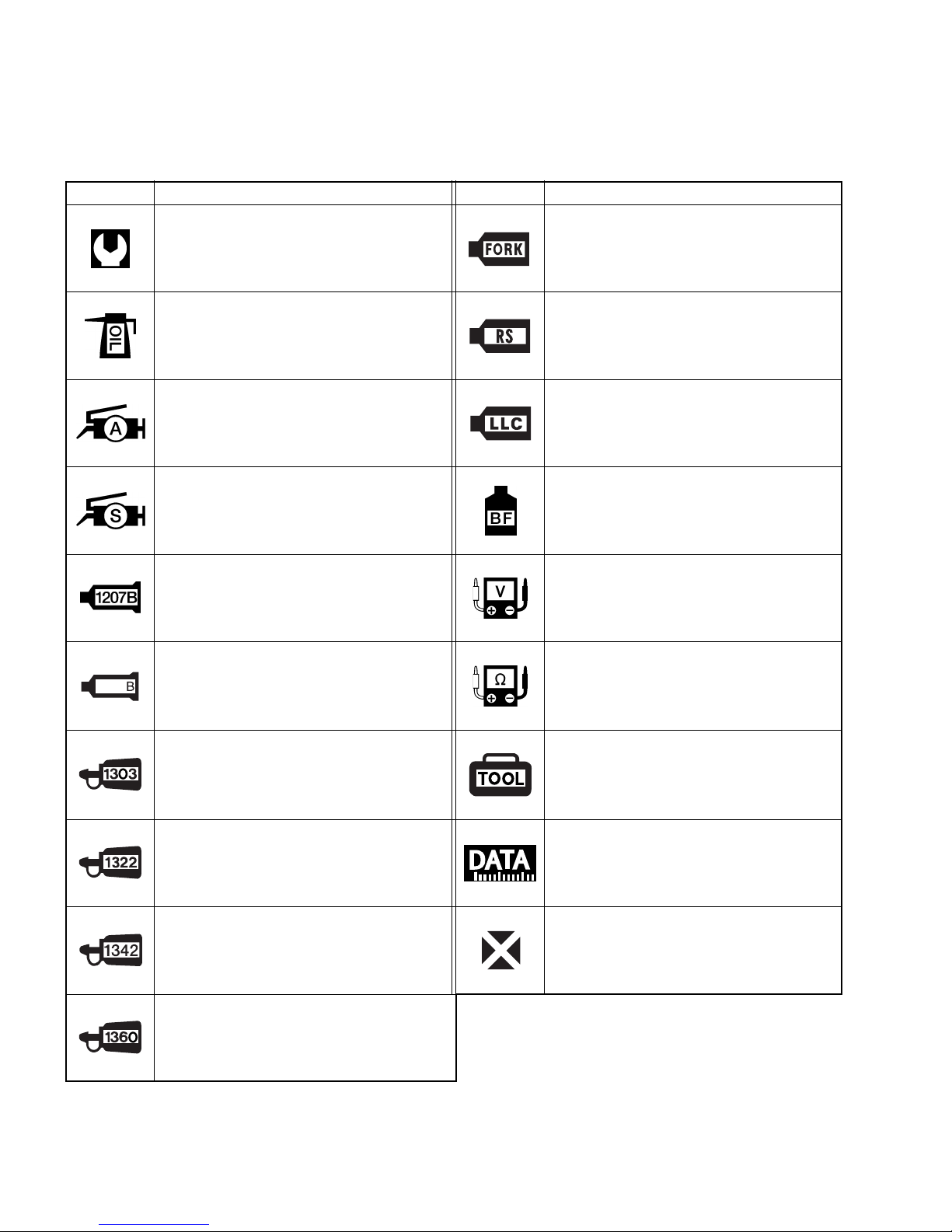
SYMBOL MARKS AND MATERIALS
Listed in the table below are the symbols indicating instructions and other information. The meaning of each
symbol is also included in the table.
SYMBOL DEFINITION SYMBOL DEFINITION
1216
Torque control required.
Data beside it indicates specified
torque.
Apply oil. Use engine oil or transmission
oil unless otherwise specified.
Apply SUZUKI SUPER GREASE “A”
or equivalent grease.
99000-25010
Apply SUZUKI SILICONE GREASE.
99000-25100
Apply SUZUKI BOND “1207B”.
99000-31140
Apply SUZUKI BOND “1216B”.
99000-31230
Use SUZUKI FORK OIL SS-05 or
equivalent fork oil.
99000-99001-SS5
Use SUZUKI REAR SUSPENSION OIL
SS-25 or equivalent rear suspension oil.
99000-99001-S25
Use engine coolant.
Apply or use brake fluid. (DOT 4)
Measure in voltage range.
Measure in resistance range.
Apply THREAD LOCK SUPER “1303”.
99000-32030
Apply THREAD LOCK SUPER “1322”
or equivalent thread lock.
99000-32110
Apply THREAD LOCK “1342”.
99000-32050
Apply THREAD LOCK SUPER “1360”.
99000-32130
Use special tool.
Indication of service data.
Replace a part with a new one when
reassembling.
GROUP INDEX
GENERAL INFORMATION
PERIODIC MAINTENANCE
TROUBLESHOOTING
MACHINE TUNING
ENGINE REMOVAL AND INSTALLATION
CYLINDER, PISTON AND EXHAUST VALVE
CLUTCH
KICK STARTER
GEARSHIFTING
TRANSMISSION AND CRANKSHAFT
1
2
3
4
5
6
7
8
9
10
FUEL SYSTEM
COOLING SYSTEM
ELECTRICAL SYSTEM
FRONT AND REAR WHEELS
FRONT AND REAR BRAKES
FRONT FORK AND STEERING
REAR SUSPENSION
SERVICING INFORMATION
11
12
13
14
15
16
17
18

GENERAL INFORMATION 1-1
GENERAL INFORMATION
CONTENTS
LOCATION OF PARTS ............................................................................... 1- 2
FUEL AND OIL RECOMMENDATION ........................................................ 1- 3
OPERATING INSTRUCTIONS .................................................................... 1- 4
STARTING THE ENGINE ...................................................................... 1- 4
STOPPING THE ENGINE ..................................................................... 1- 5
TRANSMISSION ................................................................................... 1- 5
BREAK-IN (RUNNING-IN) ........................................................................... 1- 5
WHEN THE MOTORCYCLE IS NEW ................................................... 1- 5
WHEN ENGINE PARTS ARE REPLACED ........................................... 1- 5
1
COUNTRY AND AREA CODES
The following codes stand for the applicable country(-ies) and area(-s).
CODE COUNTRY or AREA EFFECTIVE FRAME NO.
000
E-03
E-19
E-28
Japan
U. S. A.
E.U.
Canada
JS1RJ18A000 500001 –
JS1RJ18C 72 100001 –
JS1RJ18A000 500001 –
JS1RJ18C 72 100001 –

1-2 GENERAL INFORMATION
LOCATION OF PARTS
1 Clutch lever
2 Engine stop switch
3 Clutch cable adjuster
4 Throttle grip
5 Front brake lever
6 Fuel tank cap
7 Starter knob
8 Gearshift lever
9 Fuel valve
0 Kick starter lever
A Rear brake pedal
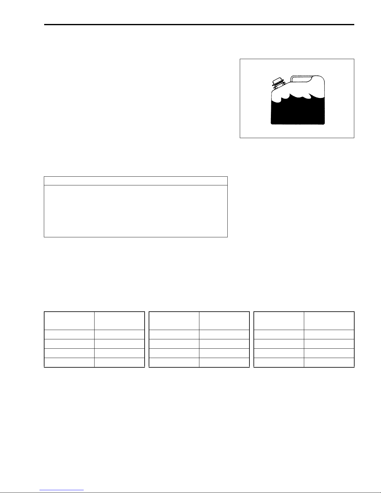
FUEL AND OIL RECOMMENDATION
This motorcycle is of the two-stroke design, which requires a
premixture of gasoline and oil.
Gasoline: Use only unleaded gasoline of at least 90
pump octane (R/2 + M/2 method). .... For
Canada
Use only unleaded gasoline of at least 95
octane (Research Method). .... For other
countries
Engine oil: MOTUL 800 2T FACTORY LINE OFF
ROAD or equivalent Two Cycle Racing
Lubricant.
Mixing ratio: 30 : 1
Fuel tank capacity: 8.0 L (2.1/1.8 US/lmp gal)
CAUTION
A mixture containing too little oil will cause piston seizure. Too much oil will cause excessive carbon formation resulting in preignition, fouled spark plug and
loss of engine power.
GENERAL INFORMATION 1-3
Mix fuel and the engine oil at the ratio of 30:1.
NOTE:
* Mix gasoline and the engine oil thoroughly when the tempera-
ture is below 0 °C (32 °F). Vegetable-based oils can separate
easier than mineral oils.
* Use premixture oil as soon as possible after mixing, or lubrica-
tion performance of the engine oil can decrease.
* Do not mix vegetable-based oil and mineral oil.
Gasoline
(L)
5.0 167 1 4.3 1 5.4
10.0 333 2 8.6 2 10.7
15.0 500 3 12.8 3 16.0
20.0 667 4 17.1 4 21.4
Oil
(ml)
Gasoline
(US gal.)
Oil
(US oz)
Gasoline
(Imp gal.)
Oil
(Imp oz)
1-4 GENERAL INFORMATION
OPERATING INSTRUCTIONS
STARTING THE ENGINE
Inspect the transmission oil level, coolant level and air cleaner
condition before starting the engine.
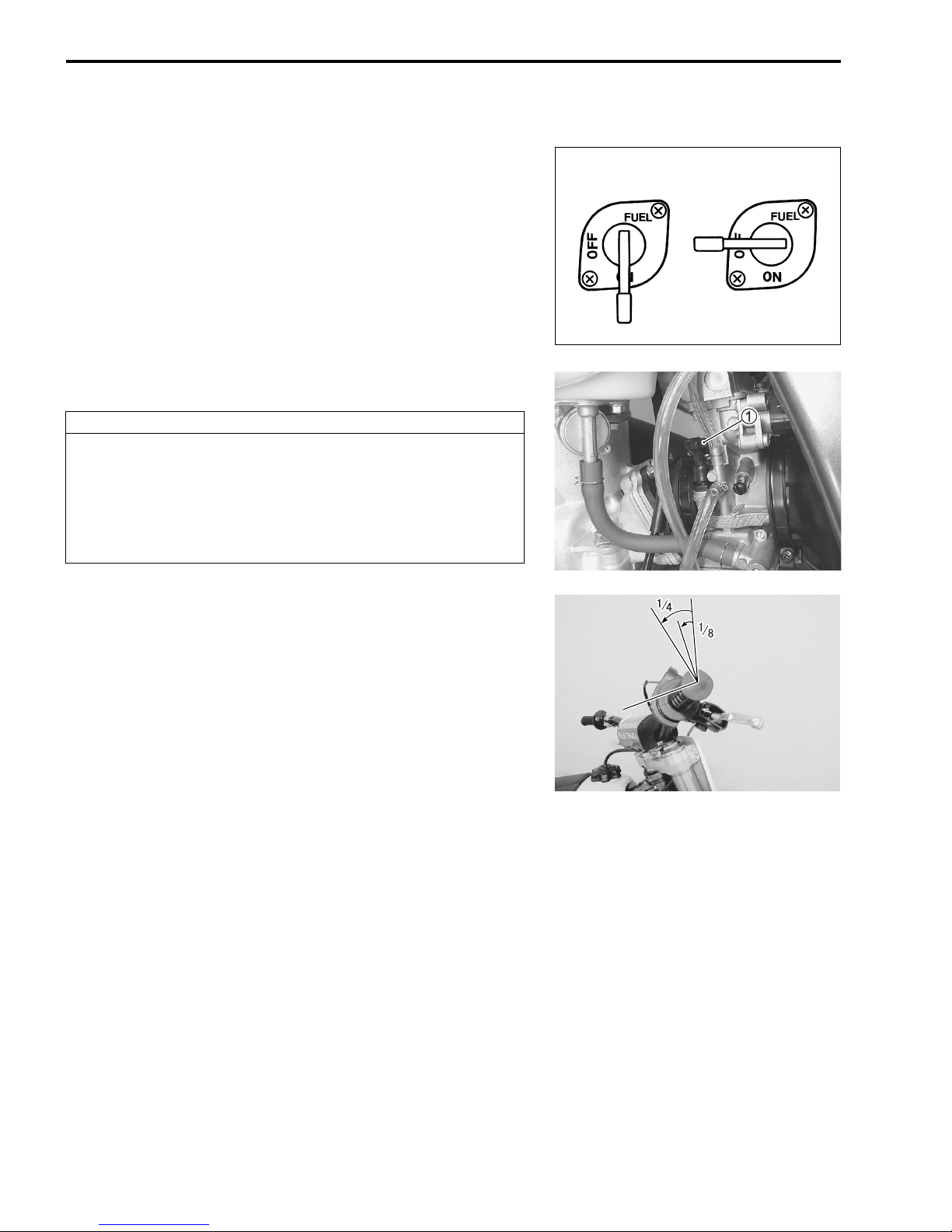
When the engine is cold:
1) Turn the fuel valve lever to the “ON” position.
2) Shift the transmission into neutral.
3) Pull the bypass (starter) knob 1.
4) Close the throttle grip completely and depress the kick
starter lever forcefully.
5) Return the bypass (starter) knob when the engine revs at
steady speed.
CAUTION
Racing the engine in neutral will exceed the engine
speed limit. Exceeding the engine speed limit can
damage the engine moving parts.
Do not race the engine at high speed to avoid the
engine damage.
When the engine is warm:
1) Turn the fuel valve lever to the “ON” position.
2) Shift the transmission into neutral.
3) Open the throttle 1/8 – 1/4 turn and depress the kick starter
lever forcefully.
ON OFF
To restart after the motorcycle has fallen:
1) Shift the transmission into neutral.
2) Open the throttle completely and depress the kick starter
lever forcefully.
3) Close the throttle gradually as engine speed increases.
4) Wait until engine revs smoothly.

STOPPING THE ENGINE
1) Shift the transmission into neutral.
2) Turn the fuel valve lever to the “OFF” position.
3) Push the engine stop switch 1 to stop the engine.
WARNING
Leaving the fuel valve in the “ON” position may cause
carburetor overflow. This can cause a fire or severe
engine damage when you start the engine.
Always leave the fuel valve in the “OFF” position
when the engine is not running.
TRANSMISSION
This motorcycle has a 5-speed transmission. Neutral is located
between low and 2nd. Engage first gear by pressing the lever
down from the neutral position. You can shift into higher gears
by lifting on the shift lever once for each gear. When neutral is
desired, press or lift the lever to the position halfway between
low and 2nd gear.
GENERAL INFORMATION 1-5
N
BREAK-IN (RUNNING-IN)
WHEN THE MOTORCYCLE IS NEW
1) Warm up the engine before starting off.
2) Ride for 1 hour using less than 1/2 throttle opening with various throttle opening.
3) Ride for 1 hour using less than 3/4 throttle opening with various throttle opening.
NOTE:
* The break-in (running-in) period is the period of greatest wear.
* The bolts and nuts of the new machine can loosen quickly. Be
sure to retighten the bolts and nuts during the break-in (running-in) period.
WHEN ENGINE PARTS ARE REPLACED
Follow the same procedure when any of the following parts are
replaced:
Piston
Piston ring
Cylinder
Crankshaft
Crankshaft bearing

– MEMO –

PERIODIC MAINTENANCE
PERIODIC MAINTENANCE 2-1
CONTENTS
PERIODIC MAINTENANCE ........................................................................ 2- 3
PERIODIC MAINTENANCE CHART .................................................... 2- 3
INSPECTION BEFORE PRACTICE ...................................................... 2- 5
INSPECTION BEFORE RACE
(All items of inspection before practice above plus) ........................ 2- 5
SPARK PLUG .............................................................................................. 2- 6
AIR CLEANER ............................................................................................. 2- 7
AIR CLEANER ELEMENT REMOVAL ................................................. 2- 7
WASHING .............................................................................................. 2- 7
INSTALLATION ..................................................................................... 2- 7
TRANSMISSION OIL ................................................................................... 2- 9
TRANSMISSION OIL LEVEL INSPECTION
AND REPLENISHMENT ....................................................................... 2- 9
TRANSMISSION OIL CHANGE ............................................................ 2-10
ENGINE COOLANT ..................................................................................... 2-11
ENGINE COOLANT LEVEL CHECK .................................................... 2-11
ENGINE COOLANT REPLENISHMENT ............................................... 2-12
ENGINE COOLING SYSTEM INSPECTION ......................................... 2-12
2
CLUTCH ....................................................................................................... 2-13
MAJOR ADJUSTMENT ........................................................................ 2-13
MINOR ADJUSTMENT ......................................................................... 2-13
THROTTLE CABLE ..................................................................................... 2-13
FUEL HOSE ................................................................................................. 2-14
FUEL VALVE ............................................................................................... 2-14
CYLINDER HEAD, CYLINDER AND PISTON ............................................ 2-15
CYLINDER HEAD ................................................................................. 2-15
CYLINDER ............................................................................................. 2-15
PISTON .................................................................................................. 2-15
EXHAUST VALVE ....................................................................................... 2-15
EXHAUST SILENCER ................................................................................. 2-16
DRIVE CHAIN AND SPROCKETS .............................................................. 2-16
DRIVE CHAIN SLACK .......................................................................... 2-16
DRIVE CHAIN ADJUSTMENT .............................................................. 2-16
20TH PITCH LENGTH ........................................................................... 2-17

2-2 PERIODIC MAINTENANCE
PERIODIC MAINTENANCE
DRIVE CHAIN LUBRICATION ............................................................. 2-17
SPROCKET INSPECTION ................................................................... 2-17
DRIVE CHAIN GUIDE, BUFFER, CONTROL ROLLER ............................. 2-18
DRIVE CHAIN GUIDE ........................................................................... 2-18
DRIVE CHAIN GUIDE BUFFER ........................................................... 2-18
DRIVE CHAIN CONTROL ROLLER .................................................... 2-18
BRAKES ...................................................................................................... 2-18
BRAKE FLUID LEVEL ......................................................................... 2-18
BRAKE PAD ......................................................................................... 2-19
FRONT BRAKE LEVER ADJUSTMENT .............................................. 2-19
BRAKE PEDAL HEIGHT ADJUSTMENT ............................................ 2-20
CONTENTS
FRONT FORK ............................................................................................. 2-20
AIR PRESSURE ADJUSTMENT .......................................................... 2-20
STEERING .................................................................................................. 2-20
REAR SUSPENSION .................................................................................. 2-21
WHEELS AND TIRES ................................................................................. 2-21
TIRE PRESSURE ................................................................................. 2-21
WHEEL RIM .......................................................................................... 2-21
SPOKE NIPPLE .................................................................................... 2-21
LUBRICATION ............................................................................................ 2-23

PERIODIC MAINTENANCE 2-3
PERIODIC MAINTENANCE
PERIODIC MAINTENANCE CHART
It is very important to inspect and maintain the machine regularly. Follow the guideline in the chart. The life
of parts varies depending on the riding conditions. Perform more often than shown in the chart if you use the
motorcycle under severe conditions.
Interval
Service
Item
Spark plug I R —
Air cleaner C — — Replace air cleaner element as necessary.
Transmission oil — R — Change after 1st initial break-in.
Cooling-system I — —
Clutch I — — Replace clutch plates as necessary.
Throttle and clutch cable I & L — —
Carburetor I — —
Fuel hose I — — Replace every 4 years.
Piston — — R
Piston ring — R —
Cylinder head, cylinder — C —
Exhaust valve — C —
Crankshaft and
transmission bearing
Exhaust silencer I — —
Drive chain I & L R — Adjust slack every 30 minutes.
Engine sprocket I — —
Rear sprocket I — —
Drive chain buffer — R —
Drive chain guide — R —
Kick starter lever I & L — —
Brake I — — Replace brake hose and fluid every year.
Front fork oil — R — Change after 1st initial break-in.
Front fork I — —
Rear suspension
system pivoting portion
races
hours
Every
race
Every
2 hours
Inspect as required
I——
Every
3 races
Every
6 hours
Every
5 races
Every
10 hours
Remarks
Replace radiator hose and engine coolant
every year.
Flushing for overhaul or storage.
Check and retighten sprocket bolts at initial
and subsequent 10 minutes of riding and
each race thereafter.
Check front fork inner tube frequently for
abnormality. Check the air pressure.
Check rear suspension system frequently
and apply the grease to the pivoting portion
as necessary.
2-4 PERIODIC MAINTENANCE
Service
Item
Interval
races
hours
Every
race
Every
2 hours
Every
3 races
Every
6 hours
Every
5 races
Every
10 hours
Remarks
Tire I — —
Spoke nipple I — —
Inspect every 20 min. up to initial 2 hours
then check before each ride.
Steering I — —
Bolts and nuts T — — Retighten every 1 hour.
NOTE: R = Replace, C = Clean, T = Tighten, I = Inspect and clean, adjust lubricate or replace if necessary,
L = Lubricate.
PERIODIC MAINTENANCE 2-5
INSPECTION BEFORE PRACTICE
WHAT TO CHECK CHECK FOR
Spark plug • Heat range, fouled electrode, tightness
• Loose high-tension cord
Air cleaner element Lubrication
Transmission oil Oil level
Coolant Coolant level
Cooling system • Radiator hose damage
• Engine coolant leak
Clutch • Play
• Smooth operation
Throttle • Play
• Smooth operation
Brake fluid Fluid level
Brakes • Brake lever position
• Brake pedal height
• Operation
Drive chain Slack, lubrication, chain joint clip condition
Drive chain guide/buffer Wear, damage
Suspension • Smooth operation
• Front fork air pressure
Wheels • Spoke tension
• Rim lock tightness or damage
Tires Tire pressure
Steering Smoothness, play
Exhaust pipe Firm fixation
Bolts and nuts Tightening torque (18-8)
INSPECTION BEFORE RACE
(All items of inspection before practice above plus)
WHAT TO CHECK CHECK FOR
Air cleaner Cleanliness
Clutch Clutch disc plates wear and distortion
Brake pads Wear
Sprockets Wear
Fuel tank • Leakage
Fuel hose Damage
Exhaust pipe Damage
Piston and Cylinder • Combustion Chamber carbon deposit
• Fuel filter clogging
• Piston head carbon deposit
• Piston and cylinder wear
2-6 PERIODIC MAINTENANCE
SPARK PLUG
Inspect the spark plug condition, electrode color, carbon deposits, spark plug gap, and washer damage, after removing the
spark plug.
NOTE:
Remove the dirt around the spark plug before removing the
spark plug to prevent dirt from entering the combustion chamber.
Inspect the porcelain tip color.
Porcelain tip color Cause
• Hot type spark plug
White (overheated)
Black (fouled)
• Advanced ignition timing
• Lean air/fuel mixture
• Deteriorated fuel
• Cold type spark plug
• Retarded ignition timing
• Rich air/fuel mixture
• Rich oil/gasoline mixture
CAUTION
Changing the spark plug heat range improperly can
damage the engine.
Select the spark plug heat range only after adjusting
the ignition timing, carburetor setting and oil/gasoline
mixture.
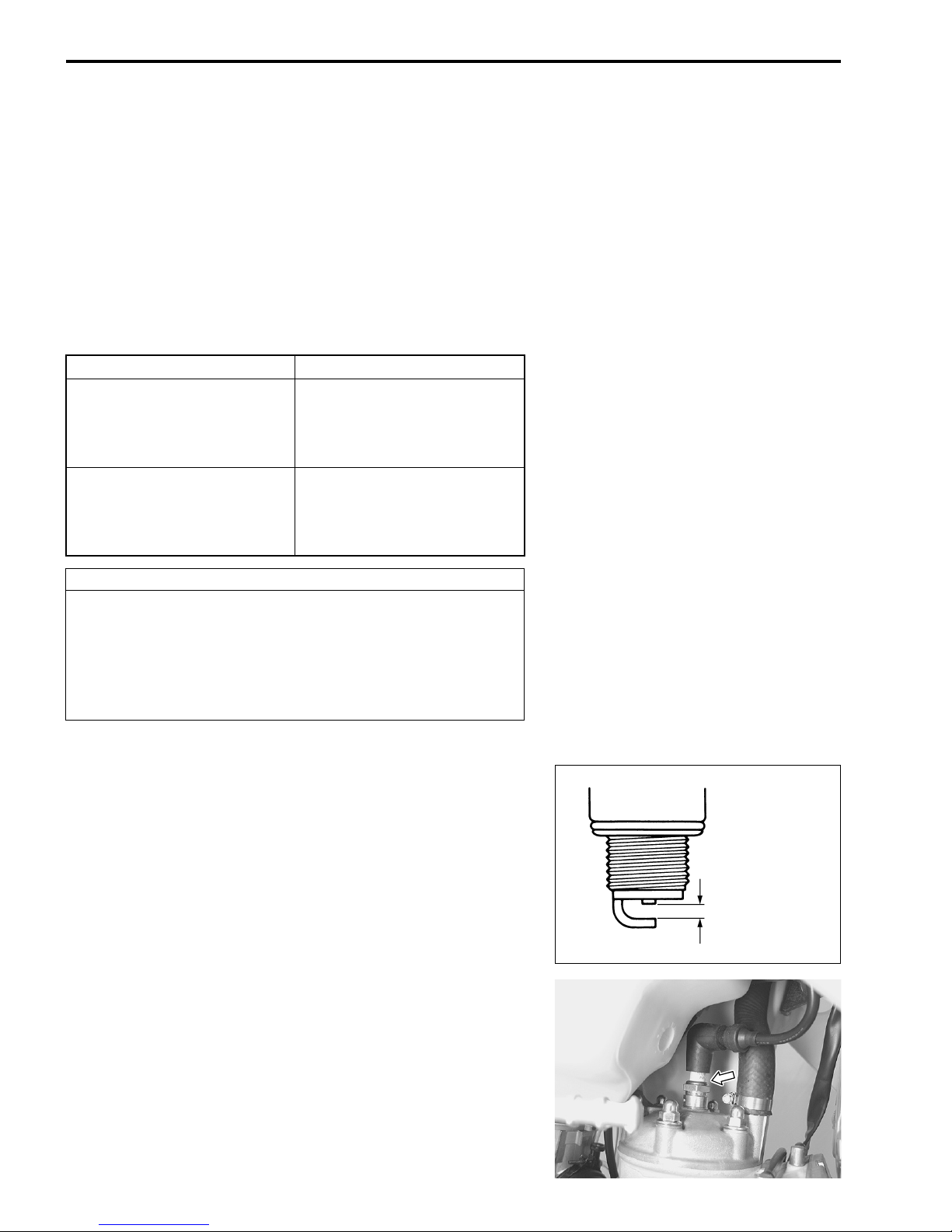
Clean the spark plug and check the spark plug gap with the
thickness gauge.
Standard Spark plug: NGK BR8EG
Spark plug gap: 0.5 – 0.6 mm (0.020 – 0.024 in)
09900-20803: Thickness gauge
Tighten the spark plug to the specified torque after tightening the
spark plug temporarily by hand.
0.5 – 0.6 mm
(0.020 – 0.024 in)
Spark plug: 20 N·m (2.0 kgf-m, 14.5 lb-ft)
AIR CLEANER
AIR CLEANER ELEMENT REMOVAL
• Remove the seat. (5-4)
• Remove the air cleaner box lid.
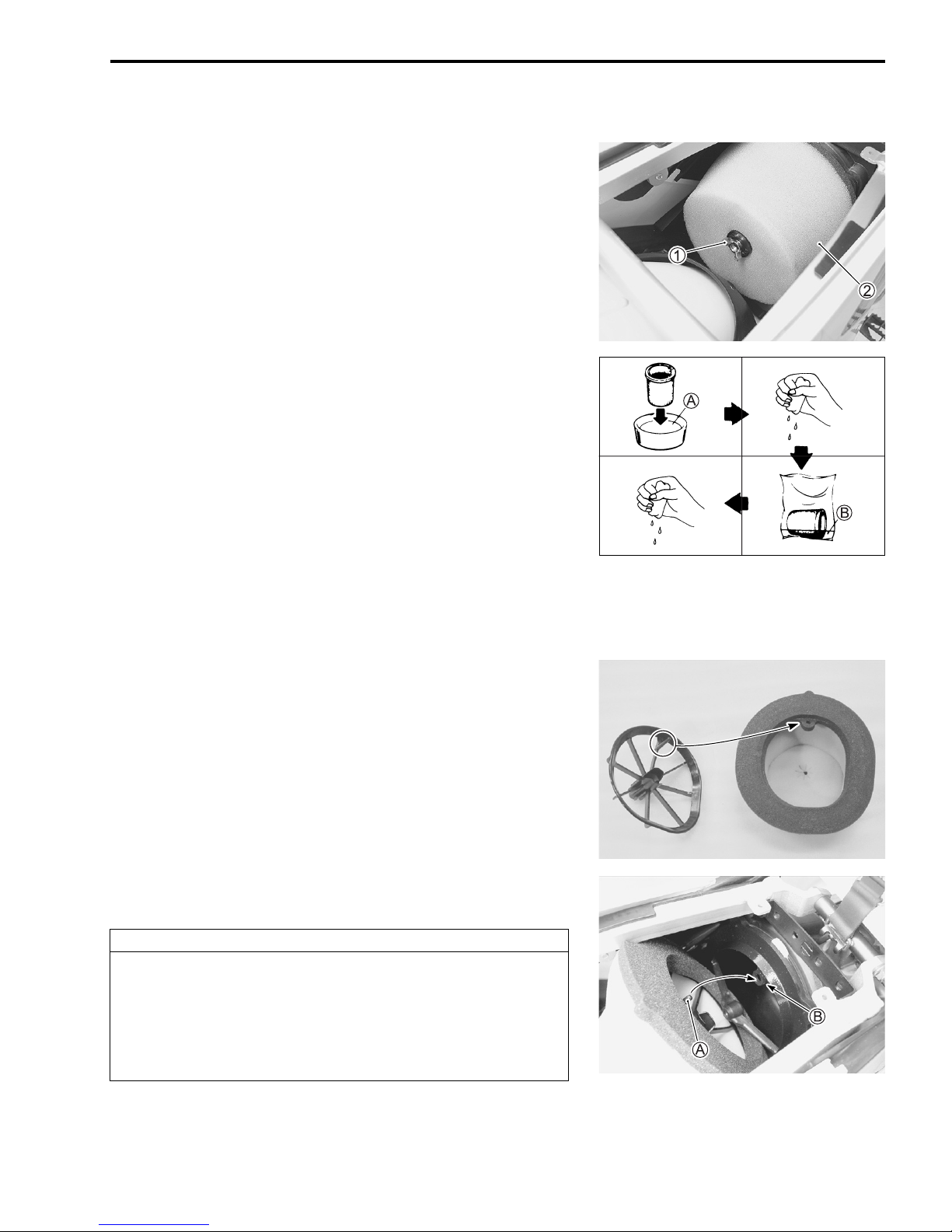
• Remove screw 1.
• Remove the element 2 from the element holder.
WASHING
• Fill a washing pan that is large enough to hold the element
with non-flammable cleaning solvent A. Immerse the element
in the solvent and wash it.
A: MOTUL AIR FILTER CLEAN or equivalent cleaning solvent
• Squeeze the element by grasping it to remove excess sol-
vent. Do not twist or wring the element, or it will develop
cracks.
• Dry the element in a plastic bag, pour in some foam filter oil B
and work the oil into the element.
B: MOTUL AIR FILTER OIL or equivalent filter oil
• Squeeze the element to remove excess oil.
PERIODIC MAINTENANCE 2-7
INSTALLATION
• Apply grease to the element base where contacts the air
cleaner box.
• Fit the element onto the element holder.
NOTE:
Fit the projection of the element holder in the hole of the element
base.
• Install them in the air cleaner box by engaging the projection
A of the element holder with the hole B of the cleaner body.
CAUTION
Improper element installation allows dust and dirt to
enter the combustion chamber. It can result in piston
and cylinder wear.
Be sure to check the element seals properly after
installing the elements.

2-8 PERIODIC MAINTENANCE
• Install the air cleaner box lid properly as shown.
NOTE:
Running the engine without the air cleaner box lid can vary the
carburetion. Do not run the engine without the air cleaner box
lid.
Lid
Cap to the front.
Air cleaner
box front wall
NOTE:
Follow the instructions below to keep the air cleaner element dry
when cleaning the motorcycle.
* Cover the element with a plastic bag.
* Install the seat.
* Cover the inlet holes on the frame covers to prevent water
from coming into the air cleaner box.
* Do not spray high pressure water to the air cleaner box.
TRANSMISSION OIL
TRANSMISSION OIL LEVEL INSPECTION
AND REPLENISHMENT
WARNING
Transmission oil and exhaust pipe can be hot enough
to burn you.
Wait until the oil drain plug and exhaust pipe become
cool enough to touch with bare hands before draining
oil.
WARNING
New and used oil and solvent can be hazardous. Children and pets may be harmed by swallowing new or
used oil or solvent. Repeated, prolonqed contact with
used engine oil may cause skin cancer, Brief contact
with used oil or solvent may irritate skin.
PERIODIC MAINTENANCE 2-9
* Keep new and used oil and solvent away from chil-
dren and pets.
* Wear a long-sleeve shirt and waterproof gloves.
* Wash with soap if oil or solvent contacts your skin.
NOTE:
Recycle or properly dispose of used oil and solvent.
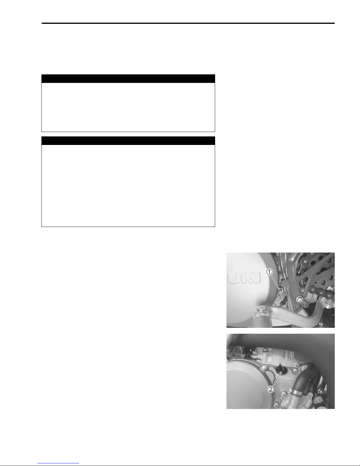
• Place the motorcycle on level ground and hold the motorcycle
vertically.
• Run the engine for a few minutes and stop it. Wait for 5 minutes.
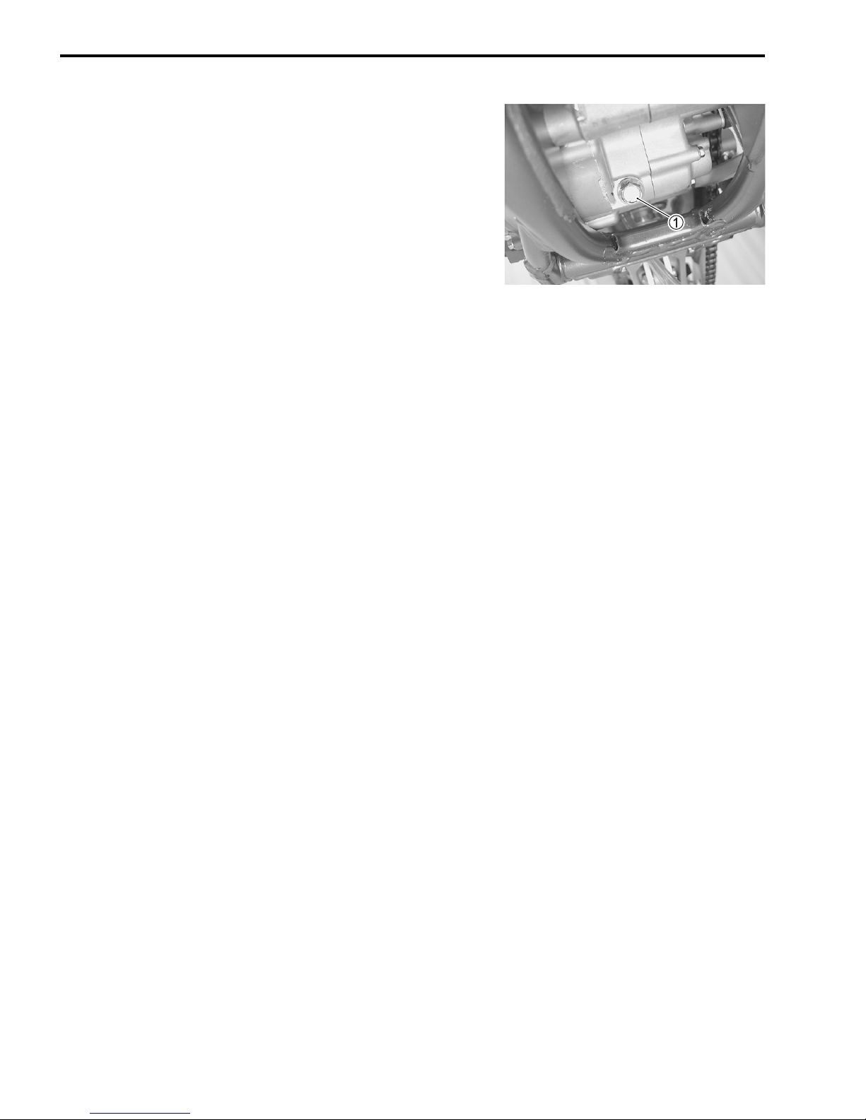
• Remove the oil check bolt 1. Check that oil comes out of the
hole.
• If oil does not come out of the hole, open oil filler cap 2 and
add the specified oil. Tighten the filler cap and oil check bolt
and inspect again as above procedure.
Transmission oil type: SAE 10W-40, API SF/SG or
SH/SJ with JASO MA
• Tighten the filler cap firmly and tighten the oil level check bolt
to the specified torque.
Oil level check bolt: 5.5 N·m (0.55 kgf-m, 4.0 lb-ft)
2-10 PERIODIC MAINTENANCE
TRANSMISSION OIL CHANGE
• Warm up the engine.
• Place the motorcycle on the level ground and hold the motorcycle vertically.
• Remove filler cap and drain plug 1. Drain oil thoroughly.
• Tighten the drain plug firmly.
Oil drain plug: 21 N·m (2.1 kgf-m, 15.0 lb-ft)
• Pour specified amount of oil.
Oil change......... 750 ml (0.8/0.7 US/Imp qt)
Overhaul............ 850 ml (0.9/0.7 US/Imp qt)
• Tighten the filler cap.
• Run the engine for a few minutes and stop it. Wait for 5 minutes.
• Inspect the oil level. (2-9)

ENGINE COOLANT
ENGINE COOLANT LEVEL CHECK
WARNING
You can be injured by scalding fluid or steam if you
open the radiator cap when the engine is hot.
Do not open the radiator cap when the engine is hot.
Wait until engine cools.
• Remove the radiator cap.
• Check that the engine coolant level is at the bottom of the inlet
hole. If not, replenish the radiator with specified engine coolant.
• Tighten the radiator cap securely.
CAUTION
Improperly tightening the radiator cap will prevent the
cooling system from reaching the specified operating
pressure and will cause coolant overflow.
PERIODIC MAINTENANCE 2-11
Tighten the radiator cap until it locks firmly.
NOTE:
* This motorcycle does not have an overflow tank at the end of
breather hose. Therefore, engine coolant level may decrease
while riding. Check the engine coolant level every time before
riding.
* When replenishing engine coolant, be sure to use engine cool-
ant mixed with distilled water at the ratio of 50:50. Adding only
water will dilute engine coolant and it may decrease cooling
performance.
* If the motorcycle is to be exposed to temperatures below –31
°C (–24 °F), the percentage of antifreeze should be increased
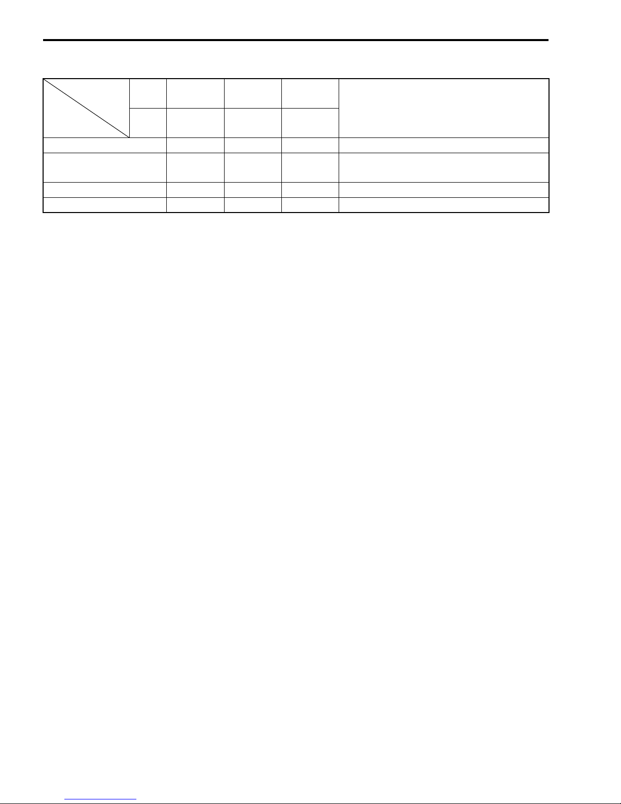
to 55% or 60%, according to figure 1.
Antifreeze density Freezing point
50% –31 °C (–24 °F)
55% –40 °C (–40 °F)
60% –55 °C (–67 °F)
Freezing point
Density (%)
Fig. 1 Engine coolant density-freezing
point curve
2-12 PERIODIC MAINTENANCE
ENGINE COOLANT REPLENISHMENT
WARNING
Engine coolant is harmful if swallowed or if it comes in
contact with your skin or eyes.
Keep engine coolant away from children and pets. Call
your doctor immediately if engine coolant is swallowed and induce vomiting. Flush eyes or skin with
water if engine coolant gets in eyes or comes in contact with skin.
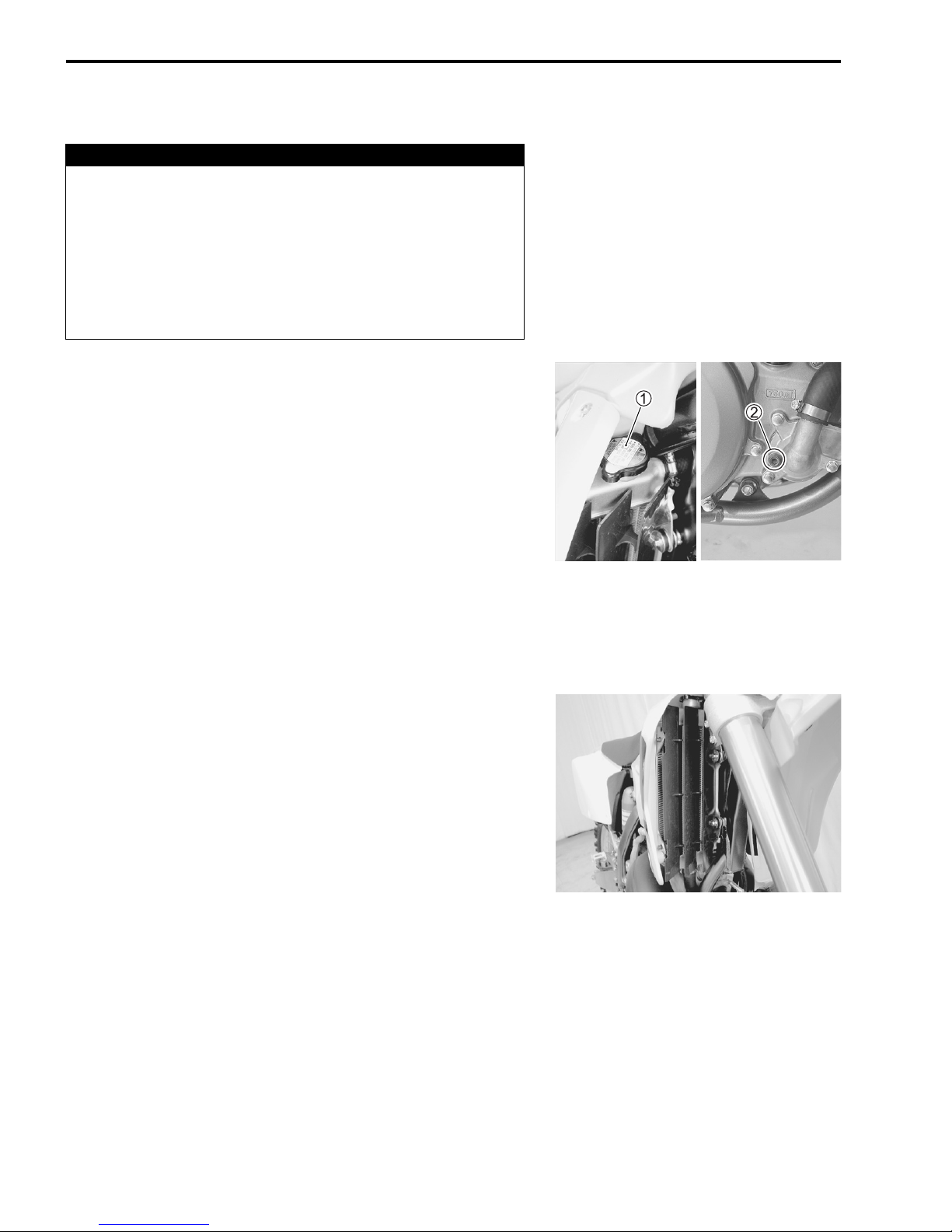
• Remove the radiator cap 1.
• Remove the drain plug 2 and drain engine coolant.
• Tighten the drain plug 2 and pour specified engine coolant.
Radiator drain plug: 5.5 N·m (0.55 kgf-m, 4.0 lb-ft)
Engine coolant capacity: 1 100 ml (1.2/1.0 US/lmp qt)
Use an anti-freeze and Summer coolant which is compatible
with aluminum radiator, mixed with distilled water at the ratio of
50 : 50.
NOTE:
The radiator, cylinder and cylinder head are made of aluminum
alloy. Using non-recommended coolant may corrode aluminum
alloy and may clog the coolant passageways.
• Bleed air from the cooling circuit.
ENGINE COOLING SYSTEM INSPECTION
Inspect the following items before practice and races.
• Engine coolant leakage
• Radiator hose cracks and deterioration
• Radiator mounting condition
• Radiator breather hose condition
• Radiator fin condition
CLUTCH
Adjust the clutch cable play as follows:
MAJOR ADJUSTMENT
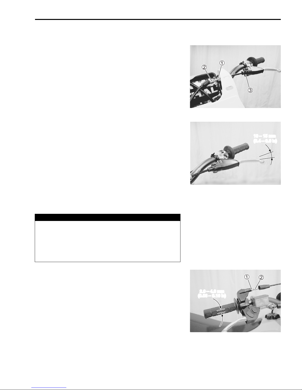
• Loosen the lock-nut 1.
• Turn the adjuster 2 so that the clutch lever obtains 10 – 15
mm (0.4 – 0.6 in) play at the clutch lever end.
• Tighten the lock-nut 1.
MINOR ADJUSTMENT
• Turn the quick adjuster 3 so that the clutch lever obtains 10 –
15 mm (0.4 – 0.6 in) play at the clutch lever end before pressure is felt.
Clutch lever play: 10 – 15 mm (0.4 – 0.6 in)
PERIODIC MAINTENANCE 2-13
10 – 15 mm
(0.4 – 0.6 in)
THROTTLE CABLE
WARNING
Inadequate throttle cable play can cause engine speed
to rise suddenly when you turn the handlebars. This
can lead to loss of rider control.
Adjust the throttle cable play so that engine speed
does not rise due to handlebar movement.
Adjust the throttle cable play as follows:
• Loosen the lock-nut 1.
• Turn the adjuster 2 so that the throttle grip obtains 2.0 – 4.0
mm (0.08 – 0.16 in) play.
Throttle cable play: 2.0 – 4.0 mm (0.08 – 0.16 in)
• Tighten the lock-nut 1.
2.0 – 4.0 mm
(0.08 – 0.16 in)

2-14 PERIODIC MAINTENANCE
• Remove the throttle housing cover.
• Apply oil to the throttle cable 3. (2-23)
• Apply oil to the throttle cable spool 4. (2-23)
FUEL HOSE
Inspect the fuel hose for damage and fuel leakage. If any
defects are found, the fuel hose must be replaced. Replace fuel
hose every four years.
FUEL VALVE
• Drain fuel from the fuel tank.
• Remove the fuel valve.
• If the fuel filter is dirty with sediment or rust, clean it with compressed air.
WARNING
* Gasoline is very explosive. Extreme care must be
taken.
* The O-ring 1 must be replaced with a new one to
prevent fuel leakage.
CYLINDER HEAD, CYLINDER AND
PISTON
CYLINDER HEAD
• Remove the cylinder head. (6-5)
• Remove carbon deposits from combustion chamber surface.
• Inspect for pinholes, cracks and other damage.
CYLINDER
• Remove the cylinder. (6-6)
• Remove carbon deposits from the exhaust port and exhaust
valve chamber.
• Check for scratches and wear on the cylinder sleeve.
PERIODIC MAINTENANCE 2-15
PISTON
• Remove the piston. (6-6)
• Remove carbon deposits from the top surface of the piston.
• Check for scratches, cracks, and wear around the piston
bosses.
• Remove minor scuffs with #1 000 – #1 200 sand paper.
• Check piston ring wear. Remove carbon deposits from the
piston ring grooves.
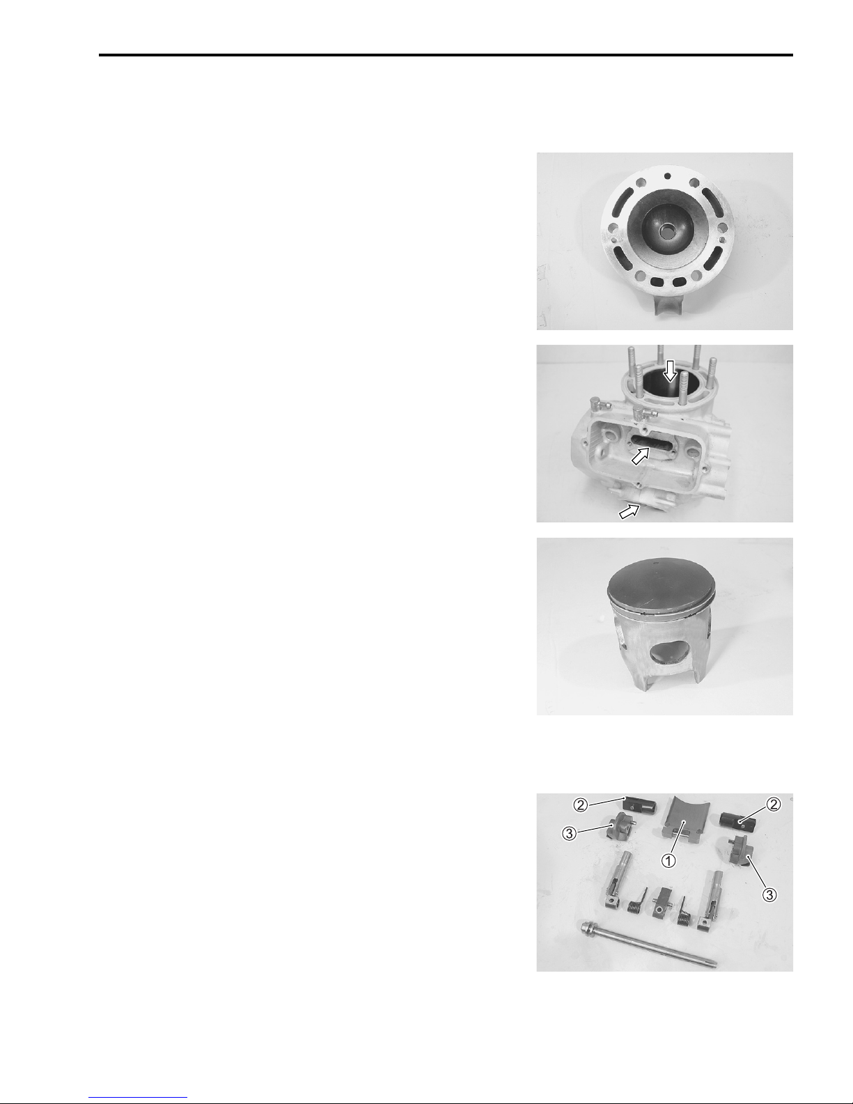
EXHAUST VALVE
• Remove the exhaust valve. (6-13)
• Remove carbon deposits from the exhaust valve 1, exhaust
side valves 2 and exhaust valve cams 3.
• Check for wear and damage.
NOTE:
If tar drops from the exhaust valve breather hose when the
motorcycle is parked, change engine oil brand because some
engine oil can accumulate tar in the exhaust valve chamber.
 Loading...