


FOREWORD
This manual contains an introductory description on the SUZUKI UY125/S and procedures for its inspection/service and overhaul of its main components.
Other information considered as generally known is not included.
Read the GENERAL INFORMATION section to familiarize yourself with the motorcycle and its maintenance. Use this section as well as other sections to use as a guide for proper inspection and service. This manual will help you know the motorcycle better so that you can assure your customers of fast and reliable service.
*This manual has been prepared on the basis of the latest specifications at the time of publication. If modifications have been made since then, differences may exist between the content of this manual and the actual motorcycle.
*Illustrations in this manual are used to show the basic principles of operation and work procedures. They may not represent the actual motorcycle exactly in detail.
*This manual is written for persons who have enough knowledge, skills and tools, including special tools, for servicing SUZUKI motorcycles. If you do not have the proper knowledge and tools, ask your authorized SUZUKI motorcycle dealer to help you.
!
Inexperienced mechanics or mechanics without the proper tools and equipment may not be able to properly perform the services described in this manual.
Improper repair may result in injury to the mechanic and may render the motorcycle unsafe for the rider and passenger.
THAI SUZUKI MOTOR CO., LTD.
© COPYRIGHT THAI SUZUKI MOTOR CO., LTD. 2005
GROUP INDEX
GENERAL INFORMATION |
1 |
|
|
|
|
|
|
|
PERIODIC MAINTENANCE |
2 |
|
|
|
|
|
|
|
ENGINE |
3 |
|
|
|
|
|
|
|
FUEL AND LUBRICATION |
4 |
|
SYSTEM |
||
|
||
|
|
|
|
|
|
CHASSIS |
5 |
|
|
|
|
|
|
|
ELECTRICAL SYSTEM |
6 |
|
|
|
|
|
|
|
SERVICING INFORMATION |
7 |
|
|
|
http://www.motorcycle.in.th

HOW TO USE THIS MANUAL
TO LOCATE WHAT YOU ARE LOOKING FOR:
1.The text of this manual is divided into sections.
2.The section titles are listed in the GROUP INDEX.
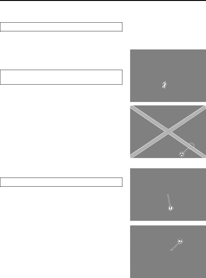
3.Holding the manual as shown at the right will allow you to find the first page of the section easily.
4.The contents are listed on the first page of each section to help you find the item and page you need.
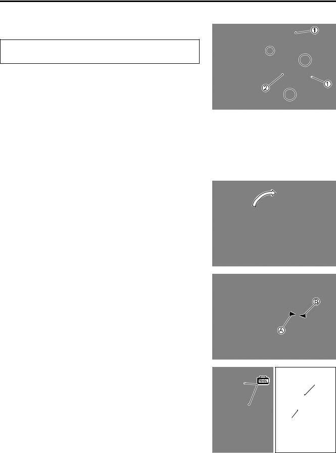
COMPONENT PARTS AND WORK TO BE DONE
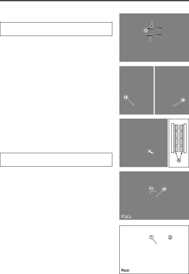
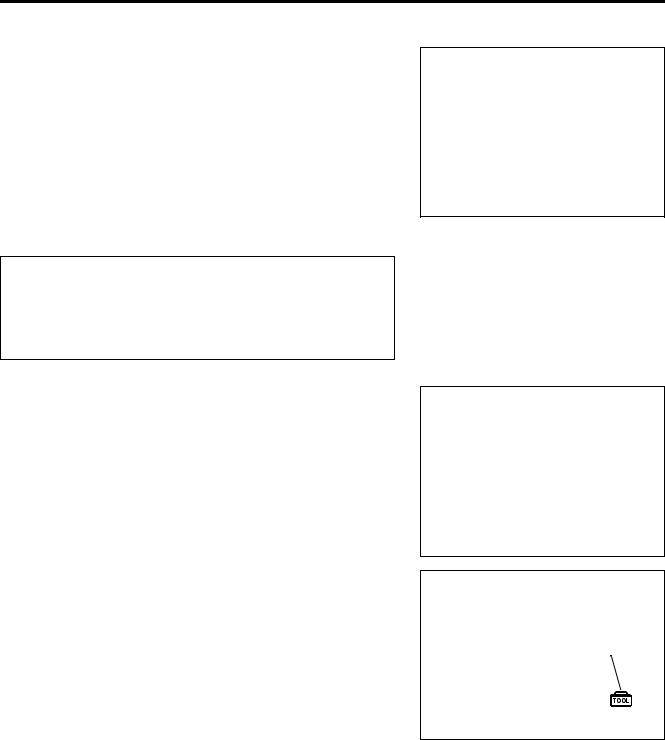
Under the name of each system or unit, is its exploded view. Work instructions and other service information such as the tightening torque, lubricating points and locking agent points, are provided.
Example: Front wheel
1 Spacer
2 Dust seal
3 Bearing
4 Front wheel spacer
5 Front wheel
6 Bearing
7 Front brake shoe
8 Dust seal
9 Speedometergear drive
0 Front brake camshaft
A Front brake panel
B Speedometergear driven
C Front brake cam lever
D Front axle
A Front axle nut
B Spoke nipple
C Frontbolt brake cam lever
"
ITEM |
N·m |
kgf-m |
|
|
|
A |
42 |
4.2 |
|
|
|
B |
4.5 |
0.45 |
|
|
|
C |
8 |
0.8 |
http://www.motorcycle.in.th
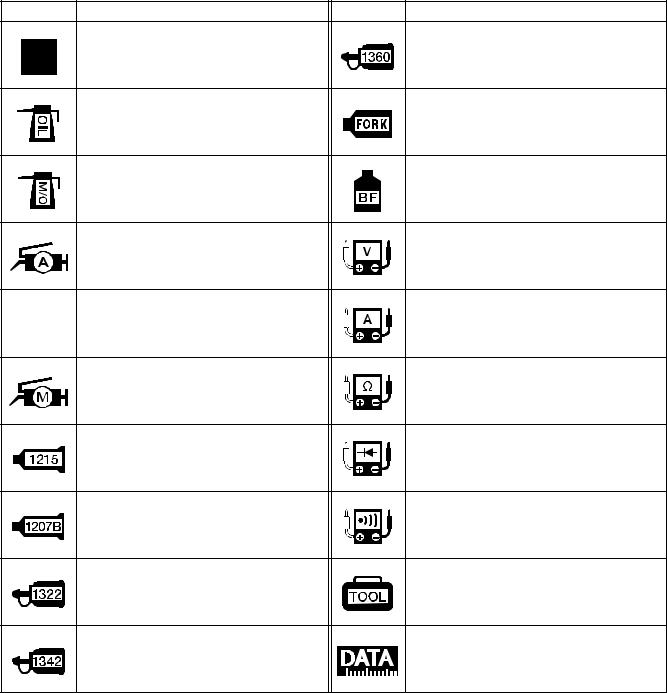
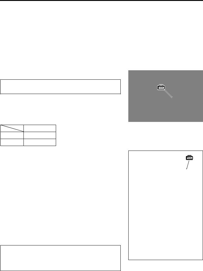
SYMBOL
Listed in the table below are the symbols indicating instructions and other information necessary for servicing. The meaning of each symbol is also included in the table.
SYMBOL |
DEFINITION |
SYMBOL |
DEFINITION |
Torque control required.
Data beside it indicates specified
Apply THREAD LOCK SUPER “1360”.
torque.
99000-32130
Apply oil. Use engine oil unless other- |
Use fork oil. |
wise specified. |
99000-99044-10G |
Apply molybdenum oil solution.
(Mixture of engine oil and SUZUKI Apply or use brake fluid. MOLY PASTE in a ratio of 1:1)
Apply SUZUKI SUPER GREASE “A”.
Measure in voltage range.
99000-25010
Apply SUZUKI SILICONE GREASE.
Measure in current range.
99000-25100
Apply SUZUKI MOLY PASTE.
Measure in resistance range.
99000-25140
Apply SUZUKI BOND “1215”.
Measure in diode test range.
99000-31110
Apply SUZUKI BOND “1207B”.
Measure in continuity test range.
99000-31140
Apply THREAD LOCK SUPER “1322”.
Use special tool.
99000-32110
Apply THREAD LOCK “1342”.
Indication of service data.
99000-32050
http://www.motorcycle.in.th
White Page
http://www.motorcycle.in.th
GENERAL INFORMATION 1-1
GENERAL INFORMATION
1
CONTENTS
WARNING/CAUTION/NOTE........................................................................ |
1- 2 |
GENERAL PRECAUTIONS ......................................................................... |
1- 2 |
SUZUKI UY125K6/SK6 (’06-MODEL) ......................................................... |
1- 4 |
SERIAL NUMBER LOCATION .................................................................... |
1- 4 |
FUEL AND OIL RECOMMENDATION ........................................................ |
1- 5 |
FUEL...................................................................................................... |
1- 5 |
ENGINE OIL .......................................................................................... |
1- 5 |
REDUCTION GEAR OIL ....................................................................... |
1- 5 |
BRAKE FLUID (UY125S) ...................................................................... |
1- 5 |
FRONT FORK OIL................................................................................. |
1- 5 |
BREAK-IN PROCEDURES.......................................................................... |
1- 5 |
SPECIFICATIONS........................................................................................ |
1- 6 |
COUNTRY AND AREA CODES
The following codes stand for the applicable country(-ies) and area(-s).
CODE |
COUNTRY or AREA |
EFFECTIVE FRAME NO. |
|
|
|
P-14 (UY125) |
Thailand |
CF48A-TH !!!!!! – |
P-14 (UY125S) |
Thailand |
CF48B-TH !!!!!! – |
http://www.motorcycle.in.th

1-2 GENERAL INFORMATION
WARNING/CAUTION/NOTE
Please read this manual and follow its instructions carefully. To emphasize special information, the symbol and the words WARNING, CAUTION and NOTE have special meanings. Pay special attention to the messages highlighted by these signal words.
!
Indicates a potential hazard that could result in death or injury.
"
Indicates a potential hazard that could result in motorcycle damage.
NOTE:
Indicates special information to make maintenance easier or instructions clearer.
Please note, however, that the warnings and cautions contained in this manual cannot possibly cover all potential hazards relating to the servicing, or lack of servicing, of the motorcycle. In addition to the WARNINGS and CAUTIONS stated, you must use good judgement and basic mechanical safety principles. If you are unsure about how to perform a particular service operation, ask a more experienced mechanic for advice.
GENERAL PRECAUTIONS
!
*Proper service and repair procedures are important for the safety of the service mechanic and the safety and reliability of the motorcycle.
*When 2 or more persons work together, pay attention to the safety of each other.
*When it is necessary to run the engine indoors, make sure that exhaust gas is forced outdoors.
*When working with toxic or flammable materials, make sure that the area you work in is wellventilated and that you follow all of the material manufacturer’s instructions.
*Never use gasoline as a cleaning solvent.
*To avoid getting burned, do not touch the engine, engine oil, radiator and exhaust system until they have cooled.
After servicing the fuel, oil, water, exhaust or brake systems, check all lines and fittings related to the system for leaks.
http://www.motorcycle.in.th
GENERAL INFORMATION 1-3
"
*If parts replacement is necessary, replace the parts with Suzuki Genuine Parts or their equivalent.
*When removing parts that are to be reused, keep them arranged in an orderly manner so that they may be reinstalled in the proper order and orientation.
*Be sure to use special tools when instructed.
*Make sure that all parts used in reassembly are clean. Lubricate them when specified.
*Use the specified lubricant, bond, or sealant.
*When removing the battery, disconnect the negative cable first and then the positive cable.
*When reconnecting the battery, connect the positive cable first and then the negative cable, and replace the terminal cover on the positive terminal.
*When performing service to electrical parts, if the service procedures do not require use of battery power, disconnect the negative cable from the battery.
*When tightening the cylinder head or case bolts and nuts, tighten the larger sizes first. Always tighten the bolts and nuts diagonally from the inside toward outside and to the specified tightening torque.
*Whenever you remove oil seals, gaskets, packing, O-rings, locking washers, self-locking nuts, cotter pins, circlips and certain other parts as specified, be sure to replace them with new ones. Also, before installing these new parts, be sure to remove any left over material from the mating surfaces.
*Never reuse a circlip. When installing a new circlip, take care not to expand the end gap larger than required to slip the circlip over the shaft. After installing a circlip, always ensure that it is completely seated in its groove and securely fitted.
*Use a torque wrench to tighten fasteners to the specified torque. Wipe off grease and oil if a thread is smeared with them.
*After reassembling, check parts for tightness and proper operation.
*To protect the environment, do not unlawfully dispose of used motor oil and other fluids: batteries and tires.
*To protect Earth’s natural resources, properly dispose of used motorcycle and parts.
http://www.motorcycle.in.th
1-4 GENERAL INFORMATION
SUZUKI UY125K6/SK6 (’06-MODEL)
RIGHT SIDE (UY125S)
LEFT SIDE (UY125)
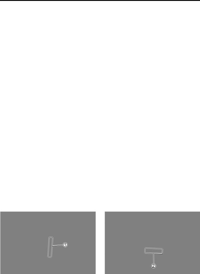
SERIAL NUMBER LOCATION
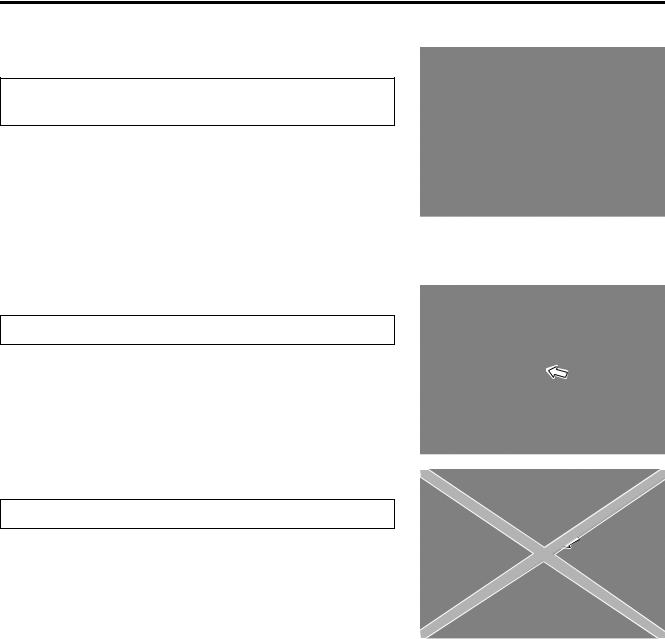
The frame serial number or V.I.N. (Vehicle Identification Number) 1 is stamped on the left side of the steering head pipe. The engine serial number 2 is located on the left side of the crankcase. These numbers are required especially for registering the machine and ordering spare parts.
http://www.motorcycle.in.th
GENERAL INFORMATION 1-5
FUEL AND OIL RECOMMENDATION
FUEL
Gasoline used should be graded 91 octane (Research Method) or higher. Unleaded gasoline is recommended.
ENGINE OIL
Oil quality is a major contributor to your engine’s performance and life. Always select good quality engine oil. Use of SF/SG or SH/SJ in API with MA in JASO.
Suzuki recommends the use of SAE 10W-40 engine oil. If SAE 10W-40 engine oil is not available, select an alternative according to the right chart.
REDUCTION GEAR OIL
Use a good quality SAE 10W-40 multi-grade motor oil.
BRAKE FLUID (UY125S)
Specification and classification: DOT 4
!
Since the brake system of this motorcycle is filled with a glycol-based brake fluid by the manufacturer, do not use or mix different types of fluid such as silicone-based and petroleum-based fluid for refilling the system, otherwise serious damage will result.
Do not use any brake fluid taken from old or used or unsealed containers.
Never re-use brake fluid left over from a previous servicing, which has been stored for a long period.
FRONT FORK OIL
Use SUZUKI FORK OIL G10 (#10) or an equivalent fork oil.
BREAK-IN PROCEDURES
During manufacture only the best possible materials are used and all machined parts are finished to a very high standard but it is still necessary to allow the moving parts to “BREAK-IN” before subjecting the engine to maximum stresses. The future performance and reliability of the engine depends on the care and restraint exercised during its early life. Refer to the following throttle position recommendations.
• Keep to these break-in throttle positions:
Initial |
800 km: Less than 1/2 throttle |
Up to 1 600 km: Less than 3/4 throttle
•Upon reaching an odometer reading of 1 600 km you can subject the motorcycle to full throttle operation for short periods of time.
http://www.motorcycle.in.th

1-6 GENERAL INFORMATION
SPECIFICATIONS
DIMENSIONS AND DRY MASS
Overall length.......................................................................... |
1 859 mm |
|
Overall width ........................................................................... |
654 mm |
|
Overall height.......................................................................... |
1 046 mm |
|
Wheelbase .............................................................................. |
1 244 mm |
|
Ground clearance ................................................................... |
145 mm |
|
Dry mass................................................................................. |
94.2 kg .......... |
UY125 |
|
95.5 kg .......... |
UY125S |
ENGINE
Type ........................................................................................ |
Four stroke, forced air-cooled, OHC |
Number of cylinders ................................................................ |
1 |
Bore ........................................................................................ |
53.5 mm |
Stroke...................................................................................... |
55.2 mm |
Displacement .......................................................................... |
124 cm³ |
Compression ratio................................................................... |
9.6 : 1 |
Carburetor............................................................................... |
MIKUNI BS26 |
Air cleaner............................................................................... |
Paper element |
Starter system......................................................................... |
Electric and kick |
Lubrication system .................................................................. |
Wet sump |
Idle speed ............................................................................... |
1 600 ± 100 rpm |
TRANSMISSION
Clutch...................................................................................... |
Dry shoe, automatic, centrifugal type |
Reduction ratio........................................................................ |
Variable change (2.700 – 0.825) |
Final reduction ratio ................................................................ |
9.264 (49/17 × 45/14) |
Drive system ........................................................................... |
V-belt drive |
CHASSIS
Front suspension .................................................................... |
Telescopic, coil spring, oil damped |
|
Rear suspension ..................................................................... |
Swingarm type, coil spring, oil damped |
|
Front fork stroke...................................................................... |
85 mm |
|
Rear wheel travel .................................................................... |
80 mm |
|
Steering angle......................................................................... |
45° (right and left) |
|
Caster ..................................................................................... |
25.6° |
|
Trail ......................................................................................... |
100 mm |
|
Turning radius ......................................................................... |
1.9 m |
|
Front brake.............................................................................. |
Drum brake .......... |
UY125 |
|
Disc brake ............ |
UY125S |
Rear brake .............................................................................. |
Drum brake |
|
Front tire size .......................................................................... |
70/90-14 M/C (34 P), tube type |
|
Rear tire size........................................................................... |
80/90-14 M/C (40 P), tube type |
|
http://www.motorcycle.in.th
|
|
GENERAL INFORMATION 1-7 |
ELECTRICAL |
|
|
Ignition type............................................................................. |
Electronic ignition (CDI) |
|
Ignition timing .......................................................................... |
10° B.T.D.C.at 1 600 rpm |
|
Spark plug ............................................................................... |
NGK CR6HSA or DENSO U20FSR-U |
|
Battery..................................................................................... |
12 |
V 12.6 kC (3.5 Ah)/10 HR |
Generator ................................................................................ |
Single-phase A.C. generator |
|
Fuse ........................................................................................ |
10 |
A |
Headlight ................................................................................. |
12 |
V 30/30 W |
Turn signal light....................................................................... |
12 |
V 10 W |
Brake light/Taillight .................................................................. |
12 |
V 18/5 W |
Speedometer light ................................................................... |
12 |
V 3.4 W |
High beam indicator light......................................................... |
12 |
V 1.7 W |
Turn signal indicator light ........................................................ |
12 |
V 1.7 W |
CAPACITIES
Fuel tank ................................................................................. |
3.7 L |
Engine oil, oil change ............................................................. |
950 ml |
with filter change................................................... |
1 050 ml |
overhaul ................................................................ |
1 100 ml |
Reduction gear oil, oil change................................................ |
100 ml |
overhaul .................................................. |
110 ml |
These specifications are subject to change without notice.
http://www.motorcycle.in.th
White Page
http://www.motorcycle.in.th

PERIODIC MAINTENANCE 2-1
PERIODIC MAINTENANCE
|
CONTENTS |
|
|
|
|
|
|
2- 2 |
|
|
|
|
|
|
|
|
|
PERIODIC MAINTENANCE SCHEDULE ...................................................... |
|
|
2 |
||
PERIODIC MAINTENANCE CHART .................................................... |
2- 2 |
|
|||
LUBRICATION POINTS |
2- 3 |
|
|
||
|
|||||
MAINTENANCE AND TUNE-UP PROCEDURES ......................................... |
2- 4 |
|
|
||
AIR CLEANER ...................................................................................... |
2- 4 |
|
|
||
EXHAUST PIPE BOLT AND MUFFLER MOUNTING NUT ................. |
2- 5 |
|
|
||
COOLING FAN FILTER ....................................................................... |
2- 5 |
|
|
||
VALVE CLEARANCE ........................................................................... |
2- 6 |
|
|
||
SPARK PLUG ....................................................................................... |
2- 7 |
|
|
||
FUEL LINE ............................................................................................ |
2- 8 |
|
|
||
ENGINE OIL AND OIL FILTER ............................................................ |
2- 8 |
|
|
||
ENGINE IDLE SPEED .......................................................................... |
2-10 |
|
|
||
THROTTLE CABLE PLAY ................................................................... |
2-10 |
|
|
||
DRIVE BELT ......................................................................................... |
2-11 |
|
|
||
REDUCTION GEAR BOX OIL .............................................................. |
2-11 |
|
|
||
BRAKE ................................................................................................. |
2-12 |
|
|
||
BRAKE HOSE AND BRAKE FLUID (UY125S) ................................... |
2-13 |
|
|
||
TIRE AND WHEELS ............................................................................. |
2-15 |
|
|
||
STEERING ............................................................................................ |
2-17 |
|
|
||
FRONT FORK ....................................................................................... |
2-17 |
|
|
||
REAR SUSPENSION ........................................................................... |
2-17 |
|
|
||
CHASSIS BOLTS AND NUTS ............................................................. |
2-18 |
|
|
||
COMPRESSION PRESSURE CHECK .......................................................... |
2-20 |
|
|
||
COMPRESSION TEST PROCEDURE ................................................. |
2-20 |
|
|
||
OIL PRESSURE CHECK ............................................................................... |
2-21 |
|
|
||
OIL PRESSURE TEST PROCEDURE ................................................. |
2-21 |
|
|
||
AUTOMATIC CLUTCH INSPECTION ........................................................... |
2-22 |
|
|
||
1. INITIAL ENGAGEMENT INSPECTION ............................................ |
2-22 |
|
|
||
2. CLUTCH “LOCK-UP” INSPECTION ............................................... |
2-22 |
|
|
||
|
|
|
|
|
|
http://www.motorcycle.in.th
2-2 PERIODIC MAINTENANCE
PERIODIC MAINTENANCE SCHEDULE
The chart below lists the recommended intervals for all the required periodic service work necessary to keep the motorcycle operating at peak performance and economy. Mileages are expressed in terms of kilometer and time for your convenience.
NOTE:
More frequent servicing may be performed on motorcycles that are used under severe conditions.
PERIODIC MAINTENANCE CHART
Interval |
km |
1 000 |
|
4 000 |
|
8 000 |
Item |
|
|
|
|
|
|
months |
5 |
|
20 |
|
40 |
|
|
|
|
|
|
|
|
Air cleaner |
|
— |
|
I |
|
I |
|
|
|
|
|
|
|
|
|
Replace every 12 000 km. |
|
|||
|
|
|
|
|||
|
|
|
|
|
|
|
Exhaust pipe bolt and muffler bolt |
|
T |
|
— |
|
T |
|
|
|
|
|
|
|
Cooling fan filter |
|
|
Clean every 3 000 km. |
|
||
|
|
|
|
|
|
|
Valve clearance |
|
I |
|
I |
|
I |
|
|
|
|
|
|
|
Spark plug |
|
— |
|
I |
|
R |
|
|
|
|
|
|
|
Fuel line |
|
— |
|
I |
|
I |
|
|
|
|
|
|
|
|
|
Replace every four years. |
|
|||
|
|
|
|
|||
|
|
|
|
|
|
|
Engine oil |
|
R |
|
R |
|
R |
|
|
|
|
|
|
|
Engine oil filter |
|
R |
|
— |
|
R |
|
|
|
|
|
|
|
Idle rpm |
|
I |
|
I |
|
I |
|
|
|
|
|
|
|
Throttle cable play |
|
I |
|
I |
|
I |
|
|
|
|
|
|
|
Drive belt |
|
— |
|
I |
|
I |
|
|
|
|
|
|
|
Final reduction gear box oil |
|
— |
|
— |
|
I |
|
|
|
|
|
|
|
Brake |
|
I |
|
I |
|
I |
|
|
|
|
|
|
|
Brake hose (UY125S) |
|
— |
|
I |
|
I |
|
|
|
|
|
|
|
|
|
Replace every four years. |
|
|||
|
|
|
|
|||
|
|
|
|
|
|
|
Brake fluid (UY125S) |
|
— |
|
I |
|
I |
|
|
|
|
|
|
|
|
|
Replace every two years. |
|
|||
|
|
|
|
|||
|
|
|
|
|
|
|
Tire and wheels |
|
— |
|
I |
|
I |
|
|
|
|
|
|
|
Steering |
|
I |
|
— |
|
I |
|
|
|
|
|
|
|
Front fork |
|
— |
|
— |
|
I |
|
|
|
|
|
|
|
Rear suspension |
|
— |
|
— |
|
I |
|
|
|
|
|
|
|
Chassis bolt and nut |
|
T |
|
T |
|
T |
|
|
|
|
|
|
|
NOTE:
I = Inspect and adjust, clean, lubricate or replace as necessary
R = Replace
T = Tighten
http://www.motorcycle.in.th

PERIODIC MAINTENANCE 2-3
LUBRICATION POINTS
Proper lubrication is important for smooth operation and long life of each working part of the motorcycle. Major lubrication points are indicated below.
 Rear brake lever holder
 Footrest pivot
Speedometer |
Side-stand pivot |
cable |
and spring hook |
Throttle cable
Front brake lever holder
 Center stand pivot
and spring hook  Speedometer gearbox
NOTE:
*Before lubricating each part, clean off any rusty spots and wipe off any grease, oil, dirt or grime.
*Lubricate exposed parts which are subject to rust, with a rust preventative spray whenever the motorcycle has been operated under wet or rainy conditions.
http://www.motorcycle.in.th
2-4 PERIODIC MAINTENANCE
MAINTENANCE AND TUNE-UP PROCEDURES
This section describes the servicing procedures for each item of the Periodic Maintenance requirements.
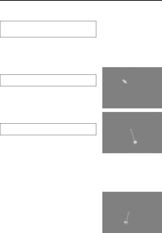
AIR CLEANER
Inspect every 4 000 km (20 months) and replace every 12 000 km thereafter.
•Place the motorcycle on the side stand.
•Remove the frame cover (left and right). (!5-10)
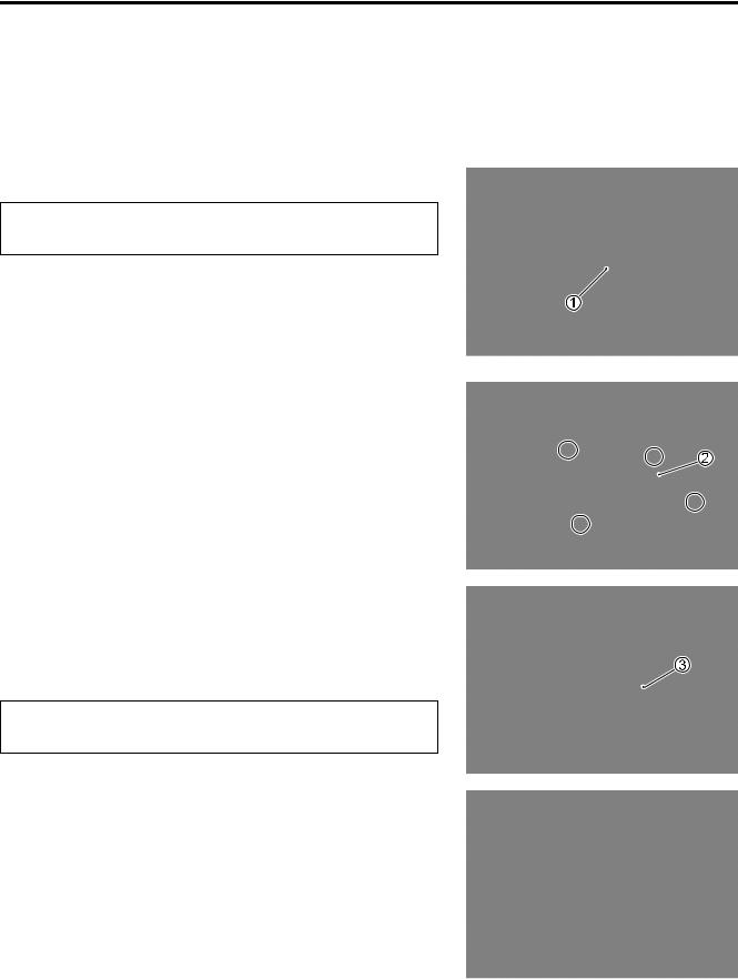
•Remove the hook 1.
•Remove the air cleaner element box cap 2 by removing the screws.
•Remove the air cleaner element 3.
•Inspect the air cleaner element for clogging.
If the air cleaner element is clogged with dust, replace the air cleaner element with a new one.
"
Do not blow the air cleaner element with compressed air.
NOTE:
If driving under dusty conditions, replace the air cleaner element more frequently. Make sure that the air cleaner is in good condition at all times. The life of the engine depends largely on this component.
•Install a new air cleaner element in the reverse order of removal.
http://www.motorcycle.in.th
PERIODIC MAINTENANCE 2-5
•Remove the drain plug from the air cleaner box to allow any water to drain out.
EXHAUST PIPE BOLT AND MUFFLER
MOUNTING NUT
Tighten initially at 1 000 km (5 months) and every 8 000 km (40 months) thereafter.
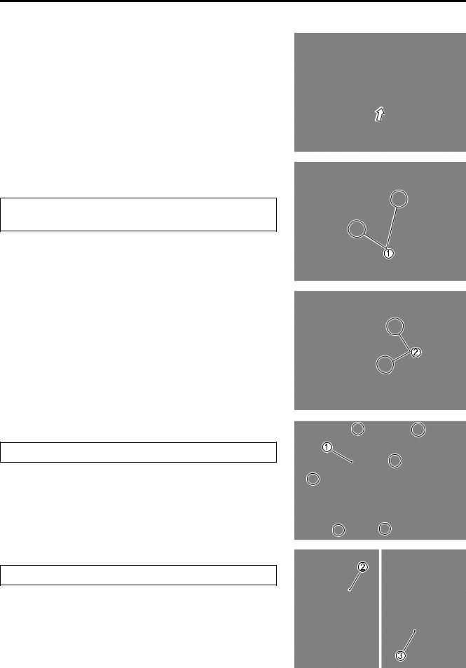
• Tighten the exhaust pipe bolts 1 and muffler mounting bolts
2.
COOLING FAN FILTER
Clean every 3 000 km.
•Remove the cooling fan cover 1.
•Remove the holder 2 and cooling fan filter 3.
•Clean the fan filter in the same manner of the air cleaner element.
• Reinstall the cleaned or new filter in the reverse order of removal.
"
Do not apply engine oil to the filter after cleaning it.
http://www.motorcycle.in.th
2-6 PERIODIC MAINTENANCE
VALVE CLEARANCE
Inspect initially at 1 000 km (5 months) and every 4 000 km (20 months) thereafter.
REMOVAL
•Remove the frame front cover. (!5-8)
•Remove the spark plug. (!2-7)
•Disconnect the breather hoses 1 and remove the head cover
2.
INSPECTION
The valve clearance specification is same for both valves. Valve clearance adjustment must be checked and adjusted, 1) at the time of periodic inspection, 2) when the valve mechanism is serviced, and 3) when the camshaft is disturbed by removing it for servicing.
NOTE:
*The piston must be at (TDC) on the compression stroke in order to check the valve clearance or to adjust valve clearance.
*The clearance specification is for COLD state.
*To turn the crankshaft for clearance checking, rotate in the nor-
mal running direction. The spark plug should be removed.
•Turn crankshaft to bring the “TDC” mark A on the cooling fan to the index mark B on the crankcase.
•Insert a thickness gauge between the valve stem end and the adjusting screw on the rocker arm.
If the clearance is out of specification, bring it into the specified range.
#Valve clearance (when cold):
IN.: 0.04 – 0.07 mm EX.: 0.10 – 0.15 mm
$09900-20803: Thickness gauge
09917-13210: Valve adjusting driver
Adjuster
Lock-nut
http://www.motorcycle.in.th
PERIODIC MAINTENANCE 2-7
•After finishing the valve clearance adjustment, reinstall the following items.
*Cylinder head cover (!3-11)
*Spark plug and plug cap (!2-7)
*Frame front cover (!5-8)
SPARK PLUG
Inspect at 4 000 km (20 months) and replace every 8 000 km (40 months) thereafter.
REMOVAL
•Remove the frame front cover. (!5-8)
•Disconnect the spark plug cap and remove the spark plug.
$09930-10121: Spark plug socket wrench set
Standard
NGK CR6HSA
DENSO U20FSR-U
CARBON DEPOSIT
Check to see the carbon deposit on the plug.
If the carbon is deposited, remove it with a spark plug cleaner machine or carefully using a tool with a pointed end.
SPARK PLUG GAP
Measure the plug gap with a thickness gauge if it is correct. If not, adjust it to the following gap.
#Spark plug gap:
Standard: 0.6 – 0.7 mm
$09900-20803: Thickness gauge
ELECTRODE’S CONDITION
Check to see the worn or burnt condition of the electrodes. If it is extremely worn or burnt, replace the plug. And also replace the plug if it has a broken insulator, damaged thread, etc.
"
0.6 – 0.7 mm
Confirm the thread size and reach when replacing the plug. If the reach is too short, carbon will be deposited on the screw portion of the plug hole and engine damage may result.
http://www.motorcycle.in.th
2-8 PERIODIC MAINTENANCE
INSTALLATION
"
Before using a spark plug wrench, carefully turn the spark plug by finger into the threads of the cylinder head to prevent damage the aluminum threads.
•Install the spark plug to the cylinder head by finger tight, and then tighten it to the specified torque.
%Spark plug: 11 N·m (1.1 kgf-m)
$09930-10121: Spark plug wrench set
FUEL LINE
Inspect every 4 000 km (20 months) thereafter. Replace every 4 years.
Inspect the fuel hoses for damage and fuel leakage. If any defects are found, the fuel hoses must be replaced.
ENGINE OIL AND OIL FILTER
ENGINE OIL REPLACEMENT
Replace initially at 1 000 km (5 months) and every 4 000 km (20 months) thereafter.
•Keep the motorcycle upright.
•Place an oil pan below the engine. Drain oil by removing the engine oil drain plug 1.
•Remove the oil filler cap 2.
•Tighten the engine oil drain plug 1 to the specified torque. Pour new oil through the oil filler hole. When performing an oil change (without oil filter replacement), the engine will hold about 950 ml of oil. Use an engine oil that meets API service classifications SF or SG and that has a viscosity rating of SAE 10W-40.
%Engine oil drain plug 1: 18 N·m (1.8 kgf-m)
•Make sure that the engine is cooled.
•Place the motorcycle on level ground and hold it vertically.
•Install the oil filler cap 2.
•Start the engine and allow it to run for a few minutes at idling speed.
http://www.motorcycle.in.th
PERIODIC MAINTENANCE 2-9
•Turn off the engine and wait minute, then check the oil level by removing the filler cap 2. If the level is below mark “L”, add oil to “F” level. (off the center stand, do not screw the filler cap.)
If the level is above mark “F”, drain oil to “F” level.
OIL FILTER REPLACEMENT
Replace initially at 1 000 km (5 months) and every 8 000 km (40 months) thereafter.
•Drain engine oil as described in the engine oil replacement procedure.
•Remove the oil filter cap 1 and oil filter 2.
•Replace the oil filter with a new one.
•Install the spring 3 correctly.
•Apply engine oil lightly to the O-rings 4 and 5.
•Install the oil filter cap and tighten the bolts securely.
%Oil filter cap bolt: 10 N·m (1.0 kgf-m)
NOTE:
*Before installing the new oil filter and oil filter cap, make sure that the spring 3 and new O-rings 4, 5 are installed correctly.
*The arrow mark A on the oil filter cap should be positioned down.
*Fit the clamp to the bolt B.
•Add new engine oil and check the oil level as described in the engine oil replacement procedure.
#Oil viscosity and classification: 10W-40 (SAE)/SF or SG (API)
#NECESSARY AMOUNT OF ENGINE OIL
Oil change |
: 950 ml |
Oil and filter change |
: 1 050 ml |
Engine overhaul |
: 1 100 ml |
"
Make sure that the oil filter is installed properly. If the filter is installed improperly, serious engine damage may result.
OIL SUMP FILTER CLEANING (!3-19 and -57)
F
L
http://www.motorcycle.in.th
2-10 PERIODIC MAINTENANCE
ENGINE IDLE SPEED
Inspect initially at 1 000 km (5 months) and every 4 000 km (20 months) thereafter.
NOTE:
Make this adjustment when the engine is hot.
•Connect an electric tachometer.
•Start up the engine and set its speed at anywhere between 1 500 and 1 700 rpm by turning throttle stop screw.
Engine idle speed: 1 600 ± 100 rpm
$09900-26006: Tachometer
THROTTLE CABLE PLAY
Inspect initially at 1 000 km (5 months) and every 4 000 km (20 months) thereafter.
Adjust the throttle cable play A with the following procedures.
•Loosen the lock-nut 1 of the throttle cable.
•Turn the adjuster 2 in or out until the throttle cable play A should be 2.0 – 4.0 mm at the throttle grip.
•Tighten the lock-nut 1 while holding the adjuster 2.
Throttle cable play A: 2.0 – 4.0 mm
&
After the adjustment is completed, check that handlebar movement does not raise the engine idle speed and that the throttle grip returns smoothly and automatically.
NOTE:
Major adjustment can be made by the carburetor side adjuster.
http://www.motorcycle.in.th
PERIODIC MAINTENANCE 2-11
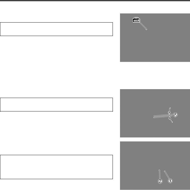
DRIVE BELT
Inspect every 4 000 km (20 months) thereafter.
•Keep the motorcycle upright.
•Remove the clutch cover. (!3-10)
•Check the contact surface for crack or other damage. If crack or other damage exists, replace the belt with a new one.
"
If grease or oil is present on the surface, decrease the belt thoroughly.
• Install the clutch cover. (!3-72)
NOTE:
Drain water from the clutch cover by removing the drain bolt A.
REDUCTION GEAR BOX OIL
Inspect every 8 000 km (40 months) thereafter.
•Keep the motorcycle upright.
•Place an oil pan below the gear case, and drain oil by remov-
ing the oil drain plug 1 and filler cap 2.
• Tighten the drain plug 1, and pour fresh oil through the oil filler.
Oil viscosity and classification: SAE 10W-40 with SF or SG
NECESSARY AMOUNT OF REDUCTION GEAR OIL
Oil change: 100 ml
Overhaul: 110 ml
http://www.motorcycle.in.th
2-12 PERIODIC MAINTENANCE
BRAKE
Inspect initially at 1 000 km (5 months) and every 4 000 km (20 months) thereafter.
BRAKE LEVER PLAY
•Adjust the brake lever play by turning the adjusting nut 1 so that the play A is 15 – 25 mm as shown.
#Brake lever play A: 15 – 25 mm
FRONT BRAKE PADS (UY125S)
The extent of brake pad wear can be checked by observing the grooved limit line A on the brake pad. When the wear exceeds the grooved limit line, replace the pads with new ones. (!5-25)
"
Replace the brake pads as a set, otherwise braking performance will be adversely affected.
BRAKE SHOW WEAR
This motorcycle is equipped with the brake lining wear limit indicator on the brake.
To check wear of the brake lining, perform the following steps:
•First, check if the brake system is properly adjusted.
•While operating the brake, check to see that the tip of indicator 1 is within the range 2 on the brake panel.
•If the tip of indicator 1 is beyond the range, the brake shoe
assembly should be replaced with a new set of shoe. (!5-13 and -49)
http://www.motorcycle.in.th
PERIODIC MAINTENANCE 2-13
BRAKE HOSE AND BRAKE FLUID (UY125S)
Inspect every 4 000 km (20 months).
Replace hoses every 4 years. Replace fluid every 2 years.
BRAKE HOSE
Check the brake hose for leakage, cracks, wear and damage. If any damages are found, replace the brake hose with a new one.
BRAKE FLUID LEVEL CHECK
•Keep the motorcycle upright and place the handlebars straight.
•Check the brake fluid level relative to the lower limit lines on
the front brake fluid reservoirs.
•When the level is below the lower limit line, replenish with brake fluid that meets the following specification.
'Specification and classification: DOT 4
&
*The brake system of this motorcycle is filled with a glycol-based brake fluid. Do not use or mix different types of fluid such as silicone-based and petro- leum-based fluids. Do not use any brake fluid taken from old, used or unsealed containers. Never re-use brake fluid left over from the last servicing or stored for a long period of time.
*Brake fluid, if it leaks, will interfere with safe running and immediately discolor painted surfaces. Check the brake hoses and hose joints for cracks and fluid leakage before riding.
http://www.motorcycle.in.th
2-14 PERIODIC MAINTENANCE
FRONT BRAKE FLUID REPLACEMENT
•Remove the handlebar cover. (!5-5)
•Place the motorcycle on a level surface and keep the handlebar straight.
•Remove the front master cylinder reservoir cap and diaphragm.
•Suck up the old brake fluid as much as possible.
•Fill the reservoir with new brake fluid.
'Specification and classification: DOT 4
•Connect a clear hose 1 to the air bleeder valve and insert the other end of the hose into a receptacle.
•Loosen the air bleeder valve and pump the brake lever until the old brake fluid is completely out of the brake system.
•Close the air bleeder valve and disconnect the clear hose. Fill the reservoir with new brake fluid to the upper end of the inspection window.
%Air bleeder valve: 7.5 N·m (0.75 kgf-m)
AIR BLEEDING FOR THE FRONT BRAKE FLUID CIRCUIT
Air trapped in the fluid circuit acts like a cushion to absorb a large proportion of the pressure developed by the master cylinder and thus interferes with the full braking performance of the brake caliper. The presence of air is indicated by “sponginess” of the brake lever and also by lack of braking force. Considering the danger to which such trapped air exposes the machine and rider, it is essential that, after remounting the brake and restoring the brake system to the normal condition, the brake fluid circuit be purged of air in the following manner:
•Fill up the master cylinder reservoir to the “UPPER” line. Place the reservoir cap to prevent entry of dirt.
•Connect a clear hose 1 to the air bleeder valve, and insert the free end of the pipe into a receptacle.
•Front brake: Bleed the air from the air bleeder valve.
http://www.motorcycle.in.th
PERIODIC MAINTENANCE 2-15
•Squeeze and release the brake lever several times in rapid succession and squeeze the lever fully without releasing it. Loosen the bleeder valve by turning it a quarter of a turn so that the brake fluid runs into the receptacle; this will remove the tension of the brake lever causing it to touch the handle-
bar grip. Then, close the valve, pump and squeeze the lever, and open the valve.
Repeat this process until the fluid flowing into the receptacle no longer contains air bubbles.
NOTE:
Replenish the brake fluid in the reservoir as necessary while bleeding the brake system. Make sure that there is always some fluid visible in the reservoir.
• Close the bleeder valve, and disconnect the clear hose.
%Air bleeder valve: 7.5 N·m (0.75 kgf-m)
Fill the reservoir with brake fluid to the “UPPER” line.
"
Handle brake fluid with care: the fluid reacts chemically with paint, plastics, rubber materials and so on.
TIRE AND WHEELS
TIRE TREAD CONDITION
Inspect every 4 000 km (20 months).
Operating the motorcycle with excessively worn tires will decrease riding stability and consequently invite a dangerous situation. It is highly recommended to replace a tire when the remaining depth of the tire tread reaches the following specification.
$09900-20805: Tire depth gauge
#Tire tread depth:
Service Limit: FRONT: 1.6 mm REAR: 1.6 mm
http://www.motorcycle.in.th
2-16 PERIODIC MAINTENANCE
TIRE PRESSURE
If the tire pressure is too high or too low, steering will be adversely affected and tire wear will increase. Therefore, maintain the correct tire pressure for good roadability and a longer tire life. Cold inflation tire pressure is as follows.
COLD INFLATION |
kPa |
kgf/cm2 |
|
TIRE PRESSURE |
|||
|
|
||
|
|
|
|
FRONT |
175 |
1.75 |
|
|
|
|
|
REAR |
225 |
2.25 |
"
The standard tire fitted on this motorcycle is a 70/ 90-14M/C 34P for the front and a 80/90-14M/C 40P for the rear. The use of tires other than those specified may cause instability. It is highly recommended to use the specified tires.
WHEEL
Make sure that the wheel runout (axial and radial) does not exceed the service limit when checked as shown. An excessive amount of runout is usually due to worn or loose wheel bearings and can be corrected by replacing the bearings. If bearing replacement fails to reduce the runout, replace the wheel.
#Wheel runout
Service Limit (axial and radial): 2.0 mm
SPOKE NIPPLES
Make sure that the nipples are tight. If necessary, tighten them with a spoke nipple wrench.
%Spoke nipple: 4.5 N·m (0.45 kgf-m) $09940-60113: Spoke nipple wrench
http://www.motorcycle.in.th
PERIODIC MAINTENANCE 2-17
STEERING
Inspect initially at 1 000 km (5 months) and every 8 000 km (40 months) thereafter.
The steering should be adjusted properly for smooth turning of handlebars and safe operation. Overtight steering prevents smooth turning of the handlebars and too loose steering will cause poor stability. Check that there is no play in the front fork. Support the motorcycle so that the front wheel is off the ground. With the wheel facing straight ahead, grasp the lower fork tubes near the axle and pull forward. If play is found, readjust the steering. (!5-46)
FRONT FORK
Inspect every 8 000 km (40 months).
Inspect the front forks for oil leakage, scoring or scratches on the outer surface of the inner tubes. Replace any defective parts, if necessary. (!5-34)
REAR SUSPENSION
Inspect every 8 000 km (40 months).
Inspect the rear shock absorber for oil leakage and mounting rubbers including engine mounting for wear and damage. Replace any defective parts, if necessary. (!5-53)
http://www.motorcycle.in.th
2-18 PERIODIC MAINTENANCE
CHASSIS BOLTS AND NUTS
Tighten initially at 1 000 km (5 months) and every 4 000 km (20 months) thereafter.
Check that all chassis bolts and nuts are tightened to their specified torque. (Refer to page 2-19 for the locations of the following bolts and nuts on the motorcycle.)
|
ITEM |
N·m |
kgf-m |
|
|
|
|
1 |
Handlebar clamp bolt |
60 |
6.0 |
|
|
|
|
2 |
Steering stem lock-nut |
90 |
9.0 |
|
|
|
|
3 |
Front fork clamp bolt |
28 |
2.8 |
|
|
|
|
4 |
Front fork cap bolt |
33 |
3.3 |
|
|
|
|
5 |
Front axle nut |
42 |
4.2 |
|
|
|
|
6 |
Engine mounting nut |
85 |
8.5 |
|
|
|
|
7 |
Rear axle nut |
120 |
12.0 |
|
|
|
|
8 |
Front brake caliper mounting bolt (UY125S) |
25 |
2.5 |
|
|
|
|
9 |
Front brake hose union bolt (UY125S) |
23 |
2.3 |
|
|
|
|
0 |
Front brake disc bolt (UY125S) |
23 |
2.3 |
|
|
|
|
A Air breeder valve (UY125S) |
7.5 |
0.75 |
|
|
|
|
|
B Front brake master cylinder bolt (UY125S) |
10 |
1.0 |
|
|
|
|
|
C Rear shock absorber mounting nut (Upper & Lower) |
29 |
2.9 |
|
|
|
|
|
D Front brake cam lever nut (UY125) |
8 |
0.8 |
|
|
|
|
|
E Rear brake cam lever nut |
11 |
1.1 |
|
|
|
|
|
F Spoke nipple |
4.5 |
0.45 |
|
http://www.motorcycle.in.th
 Loading...