


© Soundcraft Electronics Ltd. 1990 All rights reserved
Issue 1 (first draft)
Part No. ZZ2686
Information in this manual is subject to change without notice and does not represent a commitment on the part of the vendor. Soundcraft Electronics Ltd. shall not be liable for any loss or damage whatsoever arising from the use of information or any error contained in this manual.
No part of this manual may be reproduced, stored in a retrieval system, or transmitted, in any form or by any means, electronic, electrical, mechanical, optical, chemical, including photocopying and recording, for any purpose without the express written permission of Soundcraft Electronics Ltd.
It is recommended that all maintenance and service on the product should be carried out by Soundcraft Electronics Ltd. or its authorised agents. Soundcraft Electronics Ltd. cannot accept any liability whatsoever for any loss or damage caused by service, maintenance or repair by unauthorised personnel.
Soundcraft Electronics Ltd.
Unit 2
Borehamwood Ind Park
Rowley Lane
Borehamwood
Herts.
WD6 5PZ
England

User Guide
Contents
Introduction . . . . . . . . . . . . |
. . . . . . . . . |
2 |
Basic Principles of Multitrack Recording . . . . . . . |
4 |
|
Getting Started . . . . . . . . . . |
. . . . . . . . . |
6 |
Connections and Connectors |
. . . . . . . . . |
6 |
Fault Finding Guide . . . . . |
. . . . . . . . . |
9 |
Getting to know your console . . |
. . . . . . . . |
10 |
Facilities . . . . . . . . . . . |
. . . . . . . . |
10 |
Input - Channel Path . . . . . |
. . . . . . . . |
10 |
Input - Monitor Path . . . . . |
. . . . . . . . |
15 |
Group Section . . . . . . . . |
. . . . . . . . |
16 |
Master Section . . . . . . . |
. . . . . . . . |
18 |
Using your SPIRIT STUDIO Console |
. . . . . . . |
21 |
Initial Set Up . . . . . . . . . . . |
. . . . . . . . |
21 |
Applications . . . . . . . . . . . |
. . . . . . . . |
24 |
Recording . . . . . . . . . . |
. . . . . . . . |
24 |
Playback/Mix-Down . . . . . |
. . . . . . . . |
25 |
Overdubbing . . . . . . . . |
. . . . . . . . |
26 |
Live P.A. . . . . . . . . . . |
. . . . . . . . |
27 |
Care of your mixer . . . . . . . . |
. . . . . . . . |
28 |
Glossary . . . . . . . . . . . . . |
. . . . . . . . |
28 |
Selectable Options . . . . . . . . |
. . . . . . . . |
30 |
Specifications . . . . . . . . . . . |
. . . . . . . . |
31 |
Front Panel Layout . . . . . . . . |
fold out rear cover |
|
Block Diagram . . . . . . . . . . |
. inside rear cover |
|
Page 1

INTRODUCTION
Congratulations on your purchase of a SPIRIT STUDIO mixer. Owning a Soundcraft console brings you the expertise and support of one of the industry’s leading manufacturers and the results of over 17 years experience supporting some of the biggest names in the business. Packed full of features for track-laying, mixdown and overdubbing SPIRIT STUDIO provides you with access to the full range of professional multitrack techniques from an unusually compact mixer.
Designed by engineers who understand the individual needs of musicians, SPIRIT STUDIO has been built to the highest standards using quality Japanese components and employing automated assembly techniques beyond the reach of most manufacturers of compact mixers.
A rugged steel chassis is combined with moulded side trims to give protection and distinctive appearance. Custom-moulded controls, designed for the best ‘feel’ and visual clarity complement the styling, resulting in a truly professional product which is ideal for all types of multitrack recording from 8-track all the way up to 24track.
An in-line console available in two frame sizes (16/8/2 and 24/8/2) there is no shortage of inputs on SPIRIT STUDIO, since in mixdown mode the multitrack monitor inputs double as extra line inputs.
The input channels are able to accept a wide range of Microphone and Line level signals from separate input sockets. Every channel features a separate Channel and Tape Monitor section, with unique flexibility to swap functions between the two paths. The 4-band EQ is in two sections - normally the HL/LF section is before the insert point and the LOW MID and HI MID after the insert point, thus allowing separate EQ of Send and Return. If EQ to Monitor switch is pressed the HF/LF EQ is switched into the Monitor path leaving the LOW MID and HI MID section after the Insert point in the
Page 2

Channel path. The Auxiliary Sends are similarly split to give 1 Foldback and 2 Auxiliary sends in both the Channel and Monitor paths, or all four Auxiliary sends may be assigned to the Channel path.
The Monitor fader is normally a rotary control, but an INPUT REVERSE switch swaps Channel and Monitor inputs, allowing the tape return signal to be brought down the full facilities of the Channel path and mixed on the long throw channel fader. The Channel PAN control drives a matrix of routing switches to feed the signal to 8 Groups in stereo pairs, plus the Stereo mix.
The Group masters are arranged as pairs, and the outputs are normalled to the respective Tape Sends on the input channels in blocks of eight unless the Channel DIRECT switches are pressed. The Group output is also available on a separate jack socket for use as an extra send during mixdown. Groups may be routed as odd and even pairs to the Stereo mix, or as combined MONO feeds. Each group has a 16-segment LED bargraph meter.
Above the Group masters are 4 Stereo Effects Returns, with balanced inputs, 2-band shelving EQ and feeds to the two Foldback busses, the Stereo mix or summed to the local Groups in stereo.
The Master section comprises the control room monitoring facilities, Oscillator with two fixed frequencies, Talkback and Stereo mix and AFL/PFL metering.
A full description of all facilities in ‘Getting to know your console’ can be found on page 10.
SPIRIT STUDIO is designed to be as user-friendly as possible, but a few minutes spent reading through this manual will help you become familiar with the product away from the pressure of a recording session, and allow you to gain full benefit from the superb performance offered by your new mixer.
Above all, remember that your SPIRIT mixer is designed to extend your creativity. The more you explore the controls and the effect they have on the sound output, the more you will appreciate how you can influence and enhance the final sound, both by careful and creative balancing of channels and the use of
Page 3

|
|
|
|
|
|
|
|
|
|
|
|
|
|
|
|
|
|
|
|
|
|
|
|
|
|
|
|
|
|
|
|
|
BASIC PRINCIPLES OF RECORDING |
||
|
|
|
|
|
|
|
|
|
|
|
|
|
|
|
|
|
|
The Mixer |
|
|
As one would expect, the main purpose of the mixer is |
|||||
|
|
|
|
|
to combine sounds, but under precise and smooth |
|||
|
|
|
|
|
control. This is why long-throw faders are essential on |
|||
|
|
|
|
|
any professional product. The faders provide you with |
|||
|
|
|
|
|
total control of the final sound at your finger tips and |
|||
|
|
|
|
|
like an artist playing an instrument you should listen to |
|||
|
|
|
|
|
your fader movements, not look at your hands. |
|||
|
|
|
|
|
Your SPIRIT STUDIO mixer accepts a wide range of in- |
|||
|
|
|
|
|
put signals via a microphone input, for very low level |
|||
|
|
|
|
|
signals, or a line input, for higher level signals from, for |
|||
|
|
|
|
|
instance, tape machines, effects processors, etc. |
|||
|
|
|
|
|
The mixer is split into two sections. The Inputs receive, |
|||
|
|
|
|
|
match and process individual source signals, and dis- |
|||
|
|
|
|
|
tributes them at precise mix levels to a choice of |
|||
|
|
|
|
|
outputs. The Master and Group sections allow overall |
|||
|
|
|
|
|
level control of all outputs, and provides monitoring of |
|||
|
|
|
|
|
the audio signal at many points in the mixer, either on |
|||
|
|
|
|
|
headphones or meters. |
|||
|
|
|
|
|
The Equaliser controls are the most flexible and poten- |
|||
|
|
|
|
|
tially destructive feature of the mixer. They have a |
|||
|
|
|
|
|
similar effect on the frequency response of the input |
|||
|
|
|
|
|
channel as the tone controls on a hi-fi system, but with |
|||
|
|
|
|
|
much greater precision, and allow particular charac- |
|||
|
|
|
|
|
teristics of the input signal to be emphasised or |
|||
|
|
|
|
|
reduced. It is very important that you become familiar |
|||
|
|
|
|
|
with the effect each control has on the sound and this |
|||
|
|
|
|
|
is best achieved by spending time listening to the effect |
|||
|
|
|
|
|
of each control on a well-known track played through |
|||
|
|
|
|
|
the mixer. |
|||
|
|
|
|
|
The Auxiliary Sends provide a way of routing the input |
|||
|
|
|
|
|
signals to a number of secondary outputs, for artists |
|||
|
|
|
|
|
foldback, echo units or additional speaker outputs. |
|||
|
|
|
|
|
The Pan control adjusts the position of the input signal |
|||
|
|
|
|
|
within the stereo mix, and can be swept from full left, |
|||
|
|
|
|
|
through to full right. This allows particular artists to re- |
|||
|
|
|
|
|
tain their correct spatial position within the mix, |
|||
|
|
|
|
|
particularly important for stereo recording. |
|||
|
|
|
|
|
Pre-Fade-Listen(PFL) allows you to monitor the signal |
|||
|
|
|
|
|
at many points in the mixer. Pressing any PFL switch |
|||
|
|
|
|
|
places the signal at that particular point onto the control |
|||
|
|
|
|
|
room outputs (or headphones if plugged in) and the |
|||
Page 4
right meter. This allows the engineer to check the quality of the signal or to pin-point problems. Using PFL will not affect the signals on the Left and Right Mix outputs.
Each input channel and the Group and Mix outputs have an Insert ‘A’ gauge jack socket, which is a break point in the signal path. It allows the signal to be taken out of the mixer, through an external piece of equipment and then back into the mixer directly after its original exit point. The Insert point is normally bypassed by the ‘A’ gauge jack socket contacts, and is only brought into operation when a plug is inserted. Typical uses would include Effects Processors, Limiters or additional Equalisers.
The terms PRE and POST are often used in the context of Inserts, Equalisers and Auxiliary Sends, and describe whether that facility is placed before (Pre) or after (Post) another particular section. This is explained further in the detailed description of facilities.
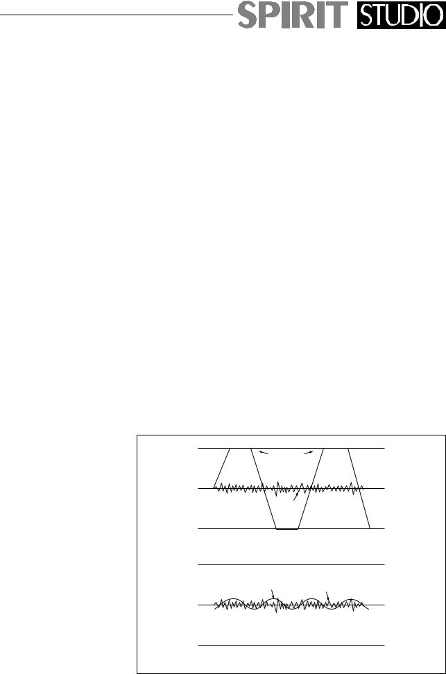
A mixer is often judged, amongst other factors, by the amount of Headroom available. This is a measure of the reserve available to cope with sudden peaks in the input signal, without distortion caused by Clipping, when the signal becomes so high that it would exceed the power supply rail voltages and is as a result limited. This commonly occurs where gain settings are incor-
Clipped
Signal
Noise
If the signal level is too high, clipping distortion may occur.
Signal Noise
If the signal level is too low it may be masked by the noise.
Page 5
rectly set or where sources are improperly matched to the mixer input. If the source signal is too high, clipping and distortion results. If the signal is too low it becomes masked by the background noise which is present to some degree in all mixers. The diagram below illustrates this point.
It is during recording that the greatest demands are made on a mixer in terms of transparency and audio quality. While a stereo recording will often be made direct to the master tape machine, multitrack machines provide greater flexibility by allowing the recording to be done in three stages. The first stage is Tracking in which individual voices or instruments, or groups of instruments are recorded as cleanly as possible on selected tracks on the multitrack machine. The second
GETTING STARTED
CONNECTIONS AND CONNECTORS
Although this may seem a simple subject, faulty connectors and cabling are the source of most sound system problems. Correctly-made cables of the proper type, with the right connectors for the job will ensure peak performance from your system with minimum noise pick-up. The following section will help you to connect SPIRIT STUDIO mixer correctly.
Two different types of audio connectors are used, 3-pin XLR and 1¤4" three pole (‘A’ gauge) jacks. These are
2. Hot(+ve) 


3. Cold(-ve) 


 1. Screen
Balanced
Input
Page 6
|
|
|
|
|
|
|
|
|
|
|
|
|
|
|
|
|
|
|
|
|
|
|
|
|
|
|
|
|
|
|
|
|
|
|
|
|
|
|
|
|
|
|
|
|
|
|
|
|
|
|
|
|
|
|
|
|
|
|
|
|
|
|
|
|
|
|
|
|
|
|
|
|
|
|
|
|
|
|
|
|
|
|
|
|
|
|
|
|
|
|
|
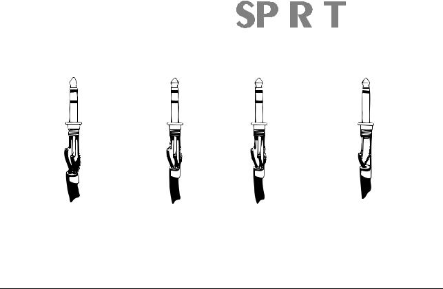
3 POLE (stereo) JACK |
|
|
|
|
|
|
|
|
|
2 POLE (mono) JACK |
||||||||||||||||||||
|
|
|
|
|
|
|
|
|
|
|
|
|
|
|
|
|
|
|||||||||||||||||||||||
Send |
|
|
|
|
|
|
|
|
|
|
|
Tip |
|
|
|
|
|
|
|
|
|
|
Hot(+ve) |
|
|
|
|
|
|
Left Signal |
|
|
|
Signal |
||||||
|
|
|
|
|
|
|
|
|
|
|
|
|
|
|
|
|
|
|
|
|
|
|
|
|
|
|||||||||||||||
Return |
|
|
|
|
|
|
|
|
Ring |
|
|
|
|
|
|
|
|
|
Cold(-ve) |
|
|
|
|
|
|
Right Signal |
|
|
|
|
||||||||||
|
|
|
|
|
|
|
|
|
|
|
|
|
|
|
|
|
|
|
|
|||||||||||||||||||||
Screen |
|
|
|
|
|
|
Sleeve |
|
|
|
|
|
|
|
|
Screen |
|
|
|
|
|
|
Ground |
|
|
|
Ground |
|||||||||||||
|
|
|
|
|
|
|
|
|
|
|
||||||||||||||||||||||||||||||
Tip 
Ring 

 Sleeve
Insert Points |
|
Line Input |
|
Headphones |
|
Unbalanced |
|
|
Aux Outputs |
|
|
|
Input |
|
|
FX Returns |
|
|
|
|
|
|
|
|
|
|
|
used in several configurations as shown in the diagrams below.
Balanced and
Unbalanced
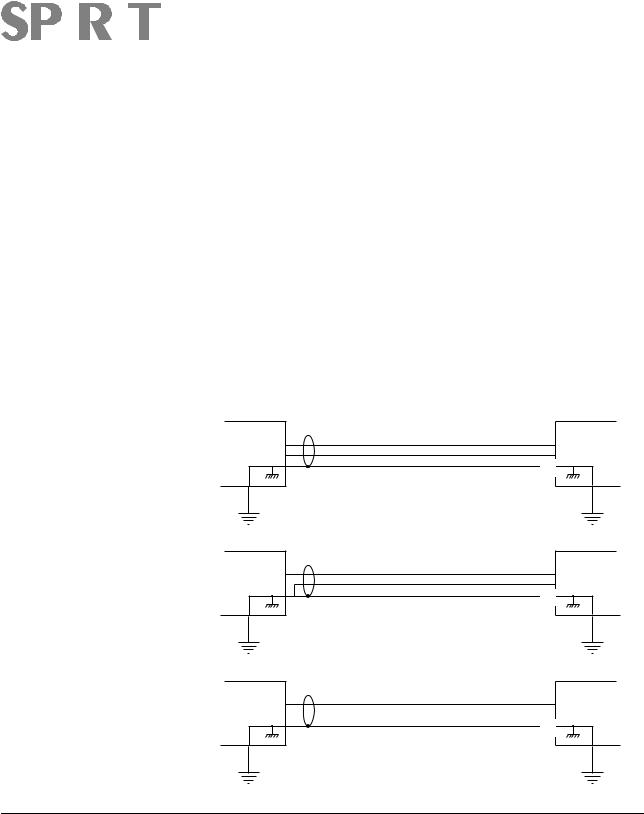
All channel inputs are balanced, i.e. there are separate +ve(hot) and -ve (cold) wires for each signal plus a ground. The design of the differential input amplifiers is such that interference picked up on these wires is cancelled out. This is because, since both wires are in close proximity, the same interference will be picked up on each wire and balanced input amplifiers will only amplify the difference between +ve(hot) and -ve(cold). Any signal on both hot and cold (i.e. noise) will not be amplified - this is known as common mode rejection (CMR.). If using an unbalanced source into a balanced input, it is a good idea to connect the source ground to the negative input. Should the source device have no connection to mains ground, then connect the shield at both ends. If there is a connection to mains ground, then the shield should only be connected to the source device ground.
Note: many modern audio/musical instruments have electronically balanced outputs which should not be unbalanced by shorting one wire to ground. Always use your inputs balanced where possible.
The mix, group and auxiliary outputs are ground compensated and provide a very effective way of optimising noise immunity, without the cost and complexity of balanced outputs. These outputs employ ground compensation techniques to cancel out the effects of variation in ground potential between the mixer
Page 7
|
|
|
|
|
|
|
|
|
|
|
|
|
|
|
|
|
|
|
|
|
and other equipment which would otherwise show up |
||
|
|
|
|
|
as hum. If the output is driving a device or amplifier |
||
|
|
|
|
|
that has an unbalanced input, connect the -ve(cold) sig- |
||
|
|
|
|
|
nal to the ground at the destination, not at the output of |
||
|
|
|
|
|
your SPIRIT STUDIO console. |
||
|
|
|
|
|
|
|
|
Polarity |
|
|
You will probably be familiar with the concept of polar- |
||||
|
|
|
|
|
ity in electrical signals and this is of particular |
||
|
|
|
|
|
importance to balanced audio signals. Just as a bal- |
||
|
|
|
|
|
anced signal is highly effective at cancelling out |
||
|
|
|
|
|
unwanted interference, so two microphones picking up |
||
|
|
|
|
|
the same signal can cancel out, or cause serious deg- |
||
|
|
|
|
|
radation of the signal if one of the cables has the +ve |
||
|
|
|
|
|
and -ve wires reversed. This phase reversal can be a |
||
|
|
|
|
|
real problem when microphones are close together and |
||
|
|
|
|
|
you should therefore take care always to connect pins |
||
|
|
|
|
|
correctly when wiring audio cables. |
||
Source BALANCED TO BALANCED Input
+ |
+ |
- |
- |
GND |
|
LINK |
|
Source |
UNBALANCED TO BALANCED |
Input |
|
+ |
+ |
|
|
- |
GND |
|
|
LINK |
|
|
Source |
UNBALANCED TO UNBALANCED |
Input |
+ |
+ |
GND
LINK
If ground link absent, or mains earth isolated from source ground, then connect shield at both ends
Grounding and
Shielding
For optimum performance it is vital that all signals are referenced to a solid, noise-free earthing point and that all signal cables have their screens connected to ground. To avoid earth ‘loops’, use balanced connections where possible and ensure that all cable screens and other signal earths are connected to ground only at their source and not at both ends.
Page 8
Avoid running audio cables or placing audio equipment, close to thyristor dimmer units or power cables.
Noise immunity is improved significantly by the use of low impedance sources, such as good quality professional microphones or the outputs from most modern audio equipment. Avoid cheaper high impedance microphones, which may suffer from interference over long cable runs, even with well-made cables.
Fault Finding Guide Repairing a sound mixing console requires specialist skills, but basic Fault Finding is within the scope of any user if a few basic rules are followed.
∙Get to know the Block Diagram of your console (see inside rear cover)
∙Get to know what each component in the system is supposed to do.
∙Learn where to look for common trouble spots.
The Block Diagram is a representative sketch of all the components of the console, showing how they connect together and how the signal flows through the system. Once you have become familiar with the various component blocks you will find the Block Diagram quite easy to follow and you will have gained a valuable understanding of the internal structure of the console.
Each Component has a specific function and only by getting to know what each part is supposed to do will you be able to tell if there is a genuine fault! Many ‘faults’ are the result of incorrect connection or control settings which may have been overlooked.
Basic Troubleshooting is a process of applying logical thought to the signal path through the console and tracking down the problem by elimination.
∙Swap input connections to check that the source is really present. Check both Mic and Line inputs.
∙Eliminate sections of the channel by using the insert point to re-route the signal to other inputs that are known to be working.
Page 9

GETTING TO KNOW YOUR CONSOLE
FACILITIES
Refer to the fold-out front panel diagram at the rear of this manual, which shows the control functions on the SPIRIT STUDIO. Each facility is described below, and is identified by a reference number.
INPUT - CHANNEL PATH
1. |
MICROPHONE INPUT |
|
The Microphone input is via a standard female XLR-3 |
|
connector and is available when the LINE switch is re- |
|
leased. It is designed to accept a wide range of |
|
balanced or unbalanced low impedance input signals. |
|
|
2. |
+48V PHANTOM POWER |
|
Each microphone input can provide the +48V neces- |
|
sary for phantom-powered mics and this may be |
|
turned on or off with the +48V switch. |
|
NOTE: The microphone should always be plugged in |
|
before switching the +48V on or off. Also you should |
|
be aware that some microphones draw an unusually |
|
large current which may overload the power supply, re- |
|
sulting in distortion. Consult your microphone supplier |
|
for guidance if necessary. |
|
Transformer-coupled dynamic microphones may be |
|
used without causing damage, even when the +48V |
|
power is connected, but care must be taken when us- |
|
ing unbalanced sources, because of the voltage |
|
present on pins 2 and 3 of the XLR connector. |
|
|
3. |
INSERT |
|
The INSERT is a break point in the input channel signal |
|
path. It allows the signal to be taken out of the mixer, |
through an external piece of equipment and then back into the mixer to continue through to the final output. The Insert is a 3-pole 1¤4" ‘A’ gauge Jack Socket, which is normally by-passed. When a jack plug is inserted, the signal path is broken at a point just before the MIDEQ section. When the HF/LF EQ is switched into the
Page 10
 Loading...