


User Guide
Contents
Introduction . . . . . . . . . . . . . |
. . |
. |
. . . . . . . . . . . |
2 |
Basic Principles of PA Mixing . . . |
. . |
. |
. . . . . . . . . . . |
3 |
Getting Started . . . . . . . . . . . |
. . |
. |
. . . . . . . . . . . |
6 |
Connections and Connectors . |
. . |
. |
. . . . . . . . . . . |
6 |
Fau lt Find ing Gu id e . . . . . . |
. . |
. |
. . . . . . . . . . . |
9 |
Getting to know your console . . . |
. . |
. |
. . . . . . . . . . |
10 |
Facilities . . . . . . . . . . . . |
. . |
. |
. . . . . . . . . . |
10 |
Inp u t Channel . . . . . . . . . |
. . |
. |
. . . . . . . . . . |
10 |
Stereo Sections . . . . . . . . . |
. . |
. |
. . . . . . . . . . |
15 |
Grou p Sections . . . . . . . . . |
. . |
. |
. . . . . . . . . . |
17 |
Master Section . . . . . . . . . |
. . |
. |
. . . . . . . . . . |
18 |
Using your SPIRIT LIVE 4 Console |
. . |
. |
. . . . . . . . . . |
20 |
Initial Set Up . . . . . . . . . . |
. . |
. |
. . . . . . . . . . |
20 |
Applications . . . . . . . . . . . . . |
. . |
. |
. . . . . . . . . . |
22 |
Pu blic Ad d ress . . . . . . . . . |
. . |
. |
. . . . . . . . . . |
22 |
Record ing . . . . . . . . . . . . |
. . |
. |
. . . . . . . . . . |
24 |
Care of your mixer . . . . . . . . . |
. . |
. |
. . . . . . . . . . |
25 |
Glossary . . . . . . . . . . . . . . . |
. . |
. |
. . . . . . . . . . |
25 |
Selectable Options . . . . . . . . . |
. . |
. |
. . . . . . . . . . |
27 |
Specifications . . . . . . . . . . . . |
. . |
. |
. . . . . . . . . . |
29 |
Front Panel Layout . . . . . . . . . |
. . |
. |
. fold out rear cover |
|
Block D iagram . . . . . . . . . . . . |
. . |
. |
. . inside rear cover |
|
Pa ge 1

INTRODUCTION
Congratu lations on you r p u rchase of a SPIRIT LIVE 4 m ixer. Ow ning a Sou nd craft console brings you the exp ertise and su p p ort of one of the ind u stry’s lead ing m anu factu rers and the resu lts of over 20 years exp erience su p p orting som e of the biggest nam es in the bu siness.
Designed by engineers w ho u nd erstand the ind ivid u al need s of m u sicians, SPIRIT LIVE 4 has been bu ilt to the highest stand ard s u sing qu ality Jap anese com p onents and em p loying au tom ated assem bly techniqu es beyond the reach of m ost m anu factu rers of com p act m ixers.
A ru gged steel chassis is com bined w ith m ou ld ed sid e trim s
to give |
p rotection |
and |
d istinctive |
ap p earance. Cu stom |
||
m ou ld ed controls, d esigned for the |
best ‘feel’ |
and |
visu al |
|||
clarity |
com p lem ent |
the |
styling, |
resu lting |
in a |
tru ly |
p rofessional p rod u ct w hich is id eal for both tou ring and fixed PA installations.
SPIRIT LIVE 4 is available in 12, 16, 24 and 32 channel fram e sizes, and the 12 and 16 channel sizes m ay be extend ed by ad d ing an 8 channel Exp and er. The Exp and er can be attached qu ickly and secu rely to the console, requ iring only a screw d river to com p lete the installation.
SPIRIT LIVE 4 incorp orates circu it technology id entical to that u sed on som e of the m ost sop histicated Sou nd craft consoles. The inp u t channels are able to accep t a w id e range of Microp hone and Line level signals from sep arate inp u t sockets. Every channel featu res w id e range gain control and Line inp u t p ad , 3-band Equ alisation w ith sw ep t Mid and LF range, p lu s a H i-Pass Filter, 5 Au xiliary Send s, PFL(Pre Fad e Listen), Peak LED, Panning to a Stereo Bu s and rou ting in p airs to fou r Ou tp u t Grou p s. Each channel has a sep arate Direct Ou tp u t and is controlled by a high-qu ality long throw fad er.
All fram e sizes are p rovid ed as stand ard w ith d ed icated stereo inp u ts, arranged in p airs. One p air is inclu d ed on the 12 channel fram e and tw o p airs on all other fram e sizes. Each stereo inp u t inclu d es a 2-band EQ and a single au xiliary send control w ith sw itching w hich allow s p refad e or p ostfad e sou rcing w ith access to three of the five Au xiliary bu sses. The stereo channel signal m ay be rou ted to either the Mix ou tp u t or to Grou p s 1 & 2 (u p p er) or Grou p s 3 & 4 (low er).
Pa ge 2

The fou r Ou tp u t Grou p s p rovid e su bm ixing to the Mix L/ R ou tp u ts or m ay feed external equ ip m ent d irectly. Each incorp orates stereo p anning and PFL m onitoring or bargrap h m etering and inclu d es an external Retu rn inp u t for effects or su bm ixing from external sou rces.
The Master section p rovid es m aster level control for the Left, Right, Mono and Au xiliary Send bu sses, w ith sep arate AFL m onitoring on each Au xiliary Send and the Mono ou tp u t.
The Mix L/ R and Grou p ou tp u ts all have insert p oints for the connection of external signal p rocessing.
Com p rehensive Talkback facilities are p rovid ed , w hich allow an external talkback m icrop hone to be rou ted to Mix L/ R, Grou p s and Au xes 1 & 2 as requ ired . Six 12-segm ent, 3-colou r p eak read ing LED bargrap h m eters p rovid e clear d isp lay of Mix L/ R, Grou p and PFL signals. Pressing any PFL or AFL
sw itch p u ts the selected |
signal onto both sid es of the |
head p hones ou tp u t, and the right bargrap h m eter. |
|
SPIRIT Live 4 is d esigned |
to be as u ser-friend ly as p ossible, |
bu t a few m inu tes sp ent |
read ing throu gh this m anu al w ill |
help you becom e fam iliar |
w ith the p rod u ct aw ay from the |
p ressu re of a live session, and allow you to gain fu ll benefit from the su p erb p erform ance offered by you r new m ixer.
Above all, rem em ber that you r SPIRIT m ixer is d esigned to extend you r creativity. The m ore you exp lore the controls and the effect they have on the sou nd ou tp u t, the m ore you w ill ap p reciate how you can influ ence and enhance the final sou nd .
BASIC PRINCIPLES OF PA MIXING
There w as a tim e w hen the P.A. system and the op erator existed only to increase the overall volu m e of the p erform ers, so that they cou ld be heard in a large room or above high am bient noise levels. This ju st isn’t tru e any m ore. The sou nd system and the sou nd engineer have becom e an integral p art of the p erform ance, and the artists are heavily d ep end ent on the op erator’s skill and the qu ality of the equ ip m ent.
The follow ing introd u ction to the basics of m ixing are inclu d ed for the benefit of those u sers w ho m ay not have any significant fam iliarity w ith sou nd equ ip m ent, and w ho are baffled by the end less jargon u sed by engineers and artists alike.
Pa ge 3

|
|
|
|
|
|
|
|
|
|
|
|
|
|
|
|
|
|
|
|
|
|
|
|
|
|
|
|
|
|
The Mixer |
As one w ou ld exp ect, the m ain p u rp ose of the m ixer is to |
||||||||
|
|
|
com bine sou nd s, bu t u nd er p recise and sm ooth control. This |
||||||
|
|
|
is w hy |
long-throw fad ers are essential on any p rofessional |
|||||
|
|
|
p rod u ct. The fad ers p rovid e you w ith clear and instinctive |
||||||
|
|
|
control of the final sou nd balance and like an artist p laying an |
||||||
|
|
|
instru m ent you shou ld listen to the effect of you r fad er |
||||||
|
|
|
m ovem ents, not look at you r hand s. |
|
|
||||
|
|
|
You r SPIRIT LIVE 4 m ixer accep ts a w id e range of inp u t |
||||||
|
|
|
signals via a m icrop hone inp u t, for very low level signals, or a |
||||||
|
|
|
line inp u t, for higher level signals from , for instance, tap e |
||||||
|
|
|
m achines, effects p rocessors, etc. |
|
|
||||
|
|
|
The m ixer is sp lit into tw o sections. The Inputs receive, m atch |
||||||
|
|
|
and p rocess ind ivid u al sou rce signals, and d istribu te them at |
||||||
|
|
|
p recise m ix levels to either a stereo Mix ou tp u t or to one of |
||||||
|
|
|
the Groups. The Master section allow s overall level control |
||||||
|
|
|
of all ou tp u ts, and p rovid es m onitoring of the au d io signal at |
||||||
|
|
|
m any p oints in the m ixer, either on head p hones or m eters. |
||||||
|
|
|
The Equaliser controls are the m ost flexible and p otentially |
||||||
|
|
|
d estru ctive featu re of the m ixer. They have a sim ilar effect on |
||||||
|
|
|
the frequ ency resp onse of the inp u t channel as the tone |
||||||
|
|
|
controls on a hi-fi system , bu t w ith |
m u ch greater p recision, |
|||||
|
|
|
and allow p articu lar characteristics of the inp u t signal to be |
||||||
|
|
|
em p hasised or red u ced . It is very im p ortant that you becom e |
||||||
|
|
|
fam iliar w ith the effect each control has on the sou nd and this |
||||||
|
|
|
is best achieved by sp end ing tim e listening to the effect of each |
||||||
|
|
|
control on a w ell-know n track p layed throu gh the m ixer. |
||||||
|
|
|
The Auxiliary Sends p rovid e a w ay of rou ting the inp u t |
||||||
|
|
|
signals to a nu m ber of second ary ou tp u ts, for artists fold back, |
||||||
|
|
|
echo u nits or ad d itional sp eaker ou tp u ts. |
||||||
|
|
|
The Pan control ad ju sts the p osition of the inp u t signal w ithin |
||||||
|
|
|
the stereo m ix, and can be sw ep t from fu ll left, throu gh to fu ll |
||||||
|
|
|
right. |
This allow s p articu lar artists to retain their correct |
|||||
|
|
|
sp atial p osition w ithin the m ix, and |
can be valu able for live |
|||||
|
|
|
effects. |
|
|
|
|
||
|
|
|
Pre-Fade-Listen(PFL) allow s you to |
m onitor the signal at |
|||||
|
|
|
m any p oints in the m ixer. Pressing any PFL sw itch p laces the |
||||||
signal at that p articu lar p oint onto the head p hones and the right m eter, to check the qu ality of the signal or to p in-p oint p roblem s. Using PFL w ill not affect the signals on the ou tp u ts from the d esk.
Pa ge 4
Each inp u t channel and the three m ain ou tp u ts have an Insert
‘A’ gau ge |
jack socket, w hich |
is |
a |
break |
p oint in the signal |
p ath. It |
allow s the signal |
to |
be |
taken |
ou t of the m ixer, |
throu gh an external p iece of equ ip m ent and then back into the m ixer d irectly after its original exit p oint. The Insert p oint is norm ally byp assed by the ‘A’ gau ge jack socket contacts, and
is only |
brou ght into |
op eration |
w hen |
a p lu g is |
inserted . |
Typ ical |
u ses w ou ld |
inclu d e Effects |
Processors, |
Lim iters, |
|
ad d itional Equ alisers |
or Delay |
u nits. |
In ad d ition, each |
||
channel has a D irect ou tp u t w hich m ay also be u sed to feed external equ ip m ent.
The term s PRE and POST are often u sed in the context of Inserts, Equ alisers and Au xiliary Send s, and d escribe w hether
that facility is p laced |
before (Pre) |
or after |
(Post) |
another |
p articu lar section. This |
is exp lained |
fu rther |
in the |
d etailed |
d escrip tion of facilities. |
|
|
|
|
A m ixer is often ju d ged , am ongst other factors, by the am ou nt of Headroom available. This is a m easu re of the reserve
available to cop e |
w ith su d d en |
p eaks in |
the inp u t |
signal, |
w ithou t d istortion |
cau sed by |
Clipping, |
w hen the |
signal |
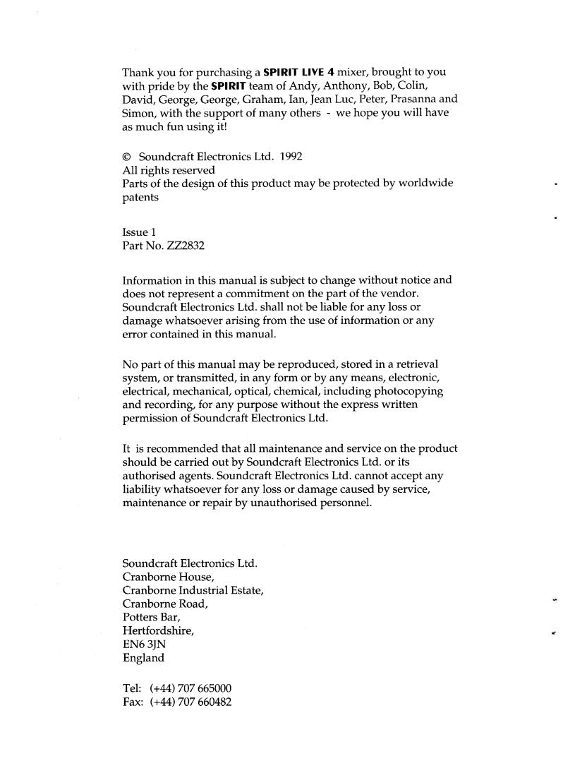
becom es so high that it w ou ld exceed the p ow er su p p ly rail voltages and is as a resu lt lim ited . This com m only occu rs w here gain settings are incorrectly set or w here sou rces are im p rop erly m atched to the m ixer inp u t. If the sou rce signal is too high, clip p ing and d istortion resu lts. If the signal is too low it becom es m asked by the backgrou nd noise w hich is p resent to som e d egree in all m ixers. The d iagram below illu strates this p oint.
Clipped
Signal
Noise
If the signal level is too high, clipping distortion may occur.
Signal Noise
If the signal level is too low it may be masked by the noise.
Pa ge 5
GETTING STARTED
CONNECTIONS AND CONNECTORS
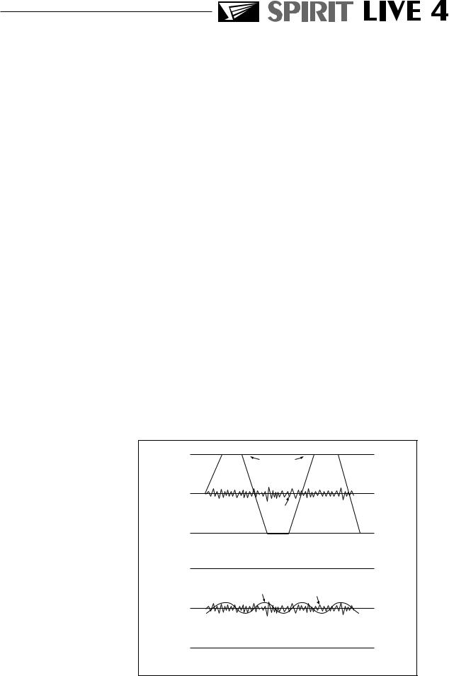
Althou gh this m ay seem a sim p le su bject, faulty connectors and cabling are the source of most sound system problems. Correctly-m ad e cables of the p rop er typ e, w ith the right connectors for the job w ill ensu re p eak p erform ance from you r system w ith m inim u m noise p ick-u p . The follow ing section w ill help you to connect SPIRIT LIVE 4 correctly.
Tw o d ifferent typ es of au d io connectors are u sed , 3-p in XLR and 1¤4" three p ole (‘A’ gau ge) jacks. These are u sed in several configu rations as show n in the d iagram s below .
|
|
|
|
|
|
|
|
|
|
2. Hot(+ve) |
|
|
|
|
|
Link 3 |
||||||
2. |
Hot(+ve) |
|
|
|
|
|
|
|
|
|
|
|
|
|
|
|
|
|
to 1 |
|
|
|
|
|
|
|
|
|
|
|
Link 3 |
|
|
|
|
|
|||||||||
|
|
|
|
|
|
|
|
|
|
|
|
|
|
|
||||||||
3. |
Cold(-ve) |
|
|
|
|
|
|
|
|
|
|
|
|
|
|
|
|
|||||
|
|
|
|
|
|
1. Screen |
to 1 |
|
|
|
|
|
|
1. Screen |
1. Screen |
|
|
|||||
|
|
|
|
|
|
|
||||||||||||||||
|
|
|
|
|
|
|
|
|
|
|
|
|
||||||||||
|
|
|
|
|
|
|
|
|
|
|
|
|||||||||||
|
|
|
|
|
|
|
||||||||||||||||
|
|
|
|
|
|
|
|
|
|
|
|
|
|
|
|
|
|
|
||||
|
|
|
|
|
|
|
|
|
|
|
|
|
|
|
|
|
|
|||||
2. Hot(+ve)
Balanced |
Unbalanced |
Unbalanced |
Input |
Output |
|
Input |
|
|
|
|
|
|
|
|
|
|
|
|
|
|
|
|
3 POLE (stereo) JACK |
|
|
|
|
2 POLE (mono) JACK |
|||||||||||||
|
|
|
|
|
|
|
|
|
|
|
|
|
|
|
|
|
|
|||||||||||||||
Send |
|
|
|
|
|
Tip |
|
|
|
|
|
|
|
Hot(+ve) |
|
|
|
Left Signal |
|
|
Signal |
|||||||||||
|
|
|
|
|
|
|
|
|
|
|
|
|
|
|
||||||||||||||||||
Return |
|
|
|
|
|
|
|
|
|
|
|
|
|
|
Ring |
|
|
|
|
|
|
Cold(-ve) |
|
|
|
Right Signal |
|
|
|
|||
|
|
|
|
|
|
|
|
|
|
|
|
|
|
|
|
|
|
|
||||||||||||||
Screen |
|
|
|
|
|
|
|
|
|
|
|
|
Sleeve |
|
|
|
|
Screen |
|
|
|
Ground |
|
|
Ground |
|||||||
|
|
|
|
|
|
|
|
|
|
|
|
|
|
|
|
|||||||||||||||||
Tip |
|
|
|
|
|
|
|
Sleeve |
|
|
|
|
|
|
|
|
|
|
|
|||||||||||||
|
|
|
|
|
|
|
|
|
|
|
|
|
|
|
||||||||||||||||||
Ring |
|
|
|
|
|
|
|
|
|
|
|
|
|
|
|
|
|
|||||||||||||||
|
|
|
|
|
|
|
|
|
|
|
|
|
||||||||||||||||||||
|
|
|
|
|
|
|
|
|
|
|
|
|
|
|
|
|
|
|
|
|||||||||||||
|
|
|
|
|
|
|
|
|
|
|
|
|
||||||||||||||||||||
Insert Points |
|
Line Input |
|
Headphones |
|
Unbalanced |
|
|
Aux Outputs |
|
|
|
Output |
|
|
FX Returns |
|
|
|
(see text) |
|
|
Direct Outputs |
|
|
|
|
|
|
|
|
|
|
|
Pa ge 6

Ba lanced a nd Unba la nced
All channel inp u ts are balanced , i.e. there are sep arate +ve(hot) and -ve (cold ) w ires for each signal p lu s a grou nd . The d esign of the d ifferential inp u t am p lifiers is su ch that interference p icked u p on these w ires is cancelled ou t. This is becau se, since both w ires are in close p roxim ity, the same
interference w ill |
be p icked |
u p on each w ire and balanced |
inp u t am p lifiers |
w ill only |
am p lify the difference betw een |
+ve(hot) and -ve(cold ). Any signal on both hot and cold (i.e. noise) w ill not be am p lified - this is know n as com m on m od e rejection (CMR). Balanced inp u ts shou ld alw ays have both +ve and -ve connected or if only an u nbalanced sou rce, the -ve p in shorted to grou nd .
N ote: m any m od ern au d io/ m u sical instru m ents have electronically balanced ou tp u ts w hich shou ld not be u nbalanced by shorting one w ire to grou nd . Alw ays u se you r inp u ts balanced w here p ossible.
The Mix L/ R and Mono ou tp u ts, Grou p and Au xiliary ou tp u ts are ground compensated and p rovid e a very effective w ay of op tim ising noise im m u nity, w ithou t the cost and com p lexity of balanced ou tp u ts. These ou tp u ts em p loy grou nd com p ensation techniqu es to cancel ou t the effects of variation in grou nd p otential betw een the m ixer and other equ ip m ent w hich w ou ld otherw ise show u p as hu m . If the ou tp u t is d riving a d evice or am p lifier that has an u nbalanced inp u t, connect the -ve(cold ) signal to the grou nd at the d estination, not at the ou tp u t of you r SPIRIT LIVE 4 console.
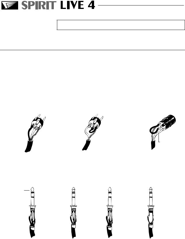
Pola rity |
You w ill p robably be fam iliar w ith the concep t of p olarity in |
||
|
electrical signals and this is of |
p articu lar im p ortance to |
|
|
balanced au d io signals. |
Ju st as a |
balanced signal is highly |
|
effective at cancelling |
ou t u nw anted interference, so tw o |
|
|
m icrop hones p icking u p the sam e signal can cancel ou t, or |
||
|
cau se seriou s d egrad ation of the signal if one of the cables has |
||
|
the +ve and -ve w ires reversed . This phase reversal can be a |
||
|
real p roblem w hen m icrop hones are close together and you |
||
|
shou ld therefore take care alw ays |
to connect p ins correctly |
|
|
w hen w iring au d io cables. |
|
|
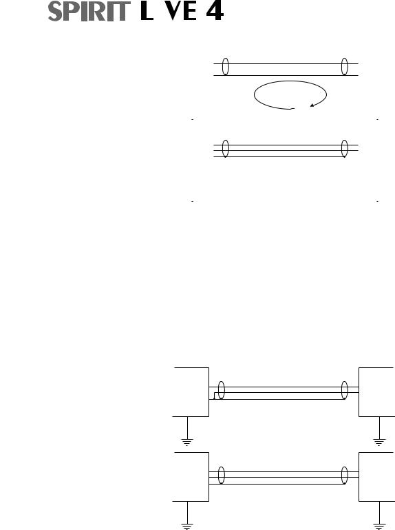
Grounding a nd Shielding For op tim u m p erform ance it is vital that all signals are referenced to a solid , noise-free earthing p oint and that all signal cables have their screens connected to grou nd . To avoid earth ‘loop s’, u se balanced connections w here p ossible and ensu re that all cable screens and other signal earths are connected to grou nd only at their sou rce and not at both end s.
Pa ge 7
|
|
|
|
|
|
|
|
|
|
|
|
|
|
|
|
|
|
|
|
|
|
|
|
|
|
|
|
|
|
|
|
|
|
|
|
|
|
|
UNBALANCED |
|
|
|
|
|
|
|
|
|
|
|
|
|
|
|
|
|
|
|
|
|
|
|
|
|
|
|
|
|
|
|
|
|
|
|
+ |
|
+ |
|
|
|
|
|
|
|
|
|
|||||||||||||
|
|
|
|
|
|
|
|
|
|
|
||||||||||||||
- |
|
|
- |
|
|
|
|
|
|
|
|
|
||||||||||||
|
|
|
|
|
Source |
|
|
Mixer |
||||||||||||||||
|
|
|
|
|
Device |
|
Ground loop |
|||||||||||||||||
|
|
|
|
|
|
|
|
|
|
|
|
|
|
through screen |
|
|
|
|
|
|
|
|
|
|
|
|
|
|
|
|
|
|
|
|
|
|
|
|
and chassis |
|
|
|
|
|
|
|
|
|
|
|
|
|
|
|
|
|
|
|
|
|
|
|
|
BALANCED INPUT |
|
|
|
|
|
|
|
|
|
|
|
|
|
|
|
|
|
|
|
|
|
|
|
|
|
|
|
|
|
|
|
|
|
|
|
|
|
|
|
|
|
|
|
|
|
|
|
|
|
|
|
|
|
|
|
|
|
|
|
|
|
|
|
|
|
|
|
|
|
|
|
|
|
|
|
|
|
|
|
|
|
|
|
|
|
+ |
|
+ |
|
|
|
|
|
|
|
|
|
|||||||||||||
|
|
|
|
|
|
|
|
|
|
|
||||||||||||||
- |
|
|
- |
|
|
|
|
|
|
|
|
|
||||||||||||
|
|
|
|
|
|
|
|
|
|
|
|
GND |
|
|
|
|
|
|
|
|
|
|
|
|
|
|
|
|
|
Source |
|
|
|
|
|
|
|
|
|
|
|
|
|||||||
|
|
|
|
|
Device |
|
|
Mixer |
||||||||||||||||
|
|
|
|
|
|
|
|
|
|
|
|
|
|
|
|
|
|
|
|
|
|
|
|
|
|
|
|
|
|
|
|
|
|
|
|
|
|
|
|
|
|
|
|
|
|
|
|
|
|
|
|
|
|
|
|
|
|
|
|
|
|
|
|
|
|
|
|
|
|
|
|
|
|
|
|
|
|
|
|
|
|
|
|
|
|
|
|
|
|
|
|
|
|
|
|
|
|
|
|
If the u se of u nbalanced connections is u navoid able, you can m im im ise noise by follow ing these w iring gu id elines:
∙On IN PUTS, u nbalance at the sou rce and u se a tw in, screened cable as thou gh it w ere balanced . (see below )
∙On OUTPUTS, connect the signal to the +ve ou tp u t p in, and the grou nd of the ou tp u t d evice to -ve. If a tw in screened cable is u sed , connect the screen only at the m ixer end . (see below )
+ |
+ |
|
- |
GND |
|
Source |
Mixer |
Device |
|
|
INPUT |
+ |
+ |
- |
GND |
GND |
|
Mixer |
Output |
Device |
|
|
OUTPUT |
Avoid ru nning au d io cables or p lacing au d io equ ip m ent, close to thyristor d im m er u nits or p ow er cables.
N oise im m u nity is im p roved significantly by the u se of low
impedance |
sou rces, |
su ch as |
good |
qu ality p rofessional |
m icrop hones |
or the |
ou tp u ts |
from |
m ost m od ern au d io |
equ ip m ent. Avoid cheap er high im p ed ance m icrop hones, w hich m ay su ffer from interference over long cable ru ns, even w ith w ell-m ad e cables.
Pa ge 8
Fault Finding Guide Repairing a sou nd m ixing console requ ires sp ecialist skills, bu t basic Fault Finding is w ithin the scop e of any u ser if a few basic ru les are follow ed .
∙Get to know the Block Diagram of you r console (see insid e rear cover)
∙Get to know w hat each com p onent in the system is su p p osed to d o.
∙Learn w here to look for com m on trou ble sp ots.
The Block D iagram (see insid e rear cover) is a rep resentative sketch of all the com p onents of the console, show ing how they connect together and how the signal flow s throu gh the system . Once you have becom e fam iliar w ith the variou s com p onent blocks you w ill find the Block Diagram qu ite easy to follow and you w ill have gained a valu able u nd erstand ing of the internal stru ctu re of the console.
Each Component has a sp ecific fu nction and only by getting to know w hat each p art is su p p osed to d o w ill you be able to tell if there is a genu ine fau lt! Many ‘fau lts’ are the resu lt of incorrect connection or control settings w hich m ay have been overlooked .
Basic Troubleshooting is a p rocess of ap p lying logical thou ght to the signal p ath throu gh the console and tracking d ow n the p roblem by elim ination.
∙Sw ap inp u t connections to check that the sou rce is really p resent. Check both Mic and Line inp u ts.
∙Elim inate sections of the channel by u sing the insert p oint
to re-rou te the signal to other inp u ts that are know n to be
working.
∙Rou te channels to d ifferent ou tp u ts or to au xiliary send s to id entify p roblem s on the Master section.
∙Com p are a su sp ect channel w ith an ad jacent channel
which has been set u p id entically. Use PFL and AFL to
m onitor the signal in each section.
Pa ge 9
 Loading...