


SPIRIT FOLIO LITE
15
6
9
12
FADER
10dB
22
1
0
1
5
4
5
4
3 3
BAL
0
1
10
9
8
8
8
10dB10dB10dB
8
2
2
1
0
1
5
4
5
4
3
3
2
2
1
0
1
5
4
5
4
3
3
2
2
1
0
1
5
4
5
4
3
3
0
1
10
9
0
1
10
9
0
1
2
3
10
9
0
1
2
3
FADERFADERFADER
000
PANPANPAN
0
INSERT INSERT INSERT
LINE LINE LINE
MMM
IC IC IC
15
6
9
12
-10
-4
U
RIGHT
L
R
INS
M
IX
IX FADER
M
8
0dB
MONITOR
0
1
9
10
PFL
-10
LEFT
AUX1
REF +4dBu
PRE
PST
4
3
2
-20
5
-10
-15
-3
-6
6
8
7
SOURCE
MONITOR
3
0
9
6
RIGHT
12
4
0
1
2
3
5
6
10
9
8
7
IX
M
FX RET
4
0
1
2
3
5
6
10
9
8
7
PSU
2TRK
2TRK TO
2TRK
M
IX
M
IX
PHANTOM
48V
O/P
LEFT
L
R
L
R
IX
M
PSU
PHONES
NTR
M
SPIRIT FOLIO LITE
12
INPUTS
1 2 3 11 12 MASTER
By
SPIRIT
FOLIO LITE
User GuideUser Guide
English
Deutsch
Français
Italiano
Español
User Guide
Handbuch
Manuel d'utilisation
Manuale Utente
Guía del usuario
1-12
13-24
25-36
37-48
49-60

Thank you for buying a SPIRIT FOLIO LITE mixer, brought to you with pride by the SPIRIT team of Peter, Graham,
Martin, Ian, Stuart, Peter, George, Colin, James, Chris, Mukesh, Andy, Candy and Simon. We hope you have as much
fun as we did!
Owning a SPIRIT console brings you the expertise and support of one of the industrys leading manufacturers and the
results of over 21 years experience supporting some of the biggest names in the business.
Built to the highest standards using quality components, FOLIO LITE is designed to be as easy to use as possible, but
some time spent NOW, looking through this manual and getting to know your new mixer will give you lots of helpful tips
and confidence, away from the pressures of an important session. Dont be afraid to experiment to find out how each
control affects the sound - this will only extend your creativity and help you to get the best from your mixer.
FFoorr
yyoouurr
oowwnn
ssaaffeettyy
aanndd
ttoo
aavvooiidd
iinnvvaalliiddaattiioonn
ooff
tthhee
wwaarrrraannttyy
pplleeaassee
rreeaadd
tthhiiss
sseeccttiioonn
ccaarreeffuullllyy..
TThhee
FOLIO LITE
ddeesskk
mmuusstt
oonnllyy
bbee
ccoonnnneecctteedd
tthhrroouugghh
tthhee
PPoowweerr
SSuuppppllyy
UUnniitt
ssuupppplliieedd..
The wires in the mains lead are coloured in accordance with the following code:
Blue: Neutral
Brown: Live
As the colours of the wires in the mains lead may not correspond with the coloured markings identifying the terminals in
your plug, proceed as follows:
o The wire which is coloured Blue must be connected to the terminal in the plug which is marked with the letter N or
coloured Black.
o The wire which is coloured Brown must be connected to the terminal in the plug which is marked with the letter L or
coloured Red.
Ensure that these colour codings are followed carefully in the event of the plug being changed.
TThhee
ppoowweerr
ssuuppppllyy
ccoonnttaaiinnss
nnoo
uusseerr--sseerrvviicceeaabbllee
ppaarrttss..
RReeffeerr
aallll
sseerrvviicciinngg
ttoo
aa
qquuaalliiffiieedd
sseerrvviiccee
eennggiinneeeerr,,
tthhrroouugghh
tthhee
aapppprroopprriiaattee
SSoouunnddccrraafftt
ddeeaalleerr..
INTRODUCTION
SAFETY PRECAUTIONS
1
In memory of Kousuke Matsui A Man of Spirit
22
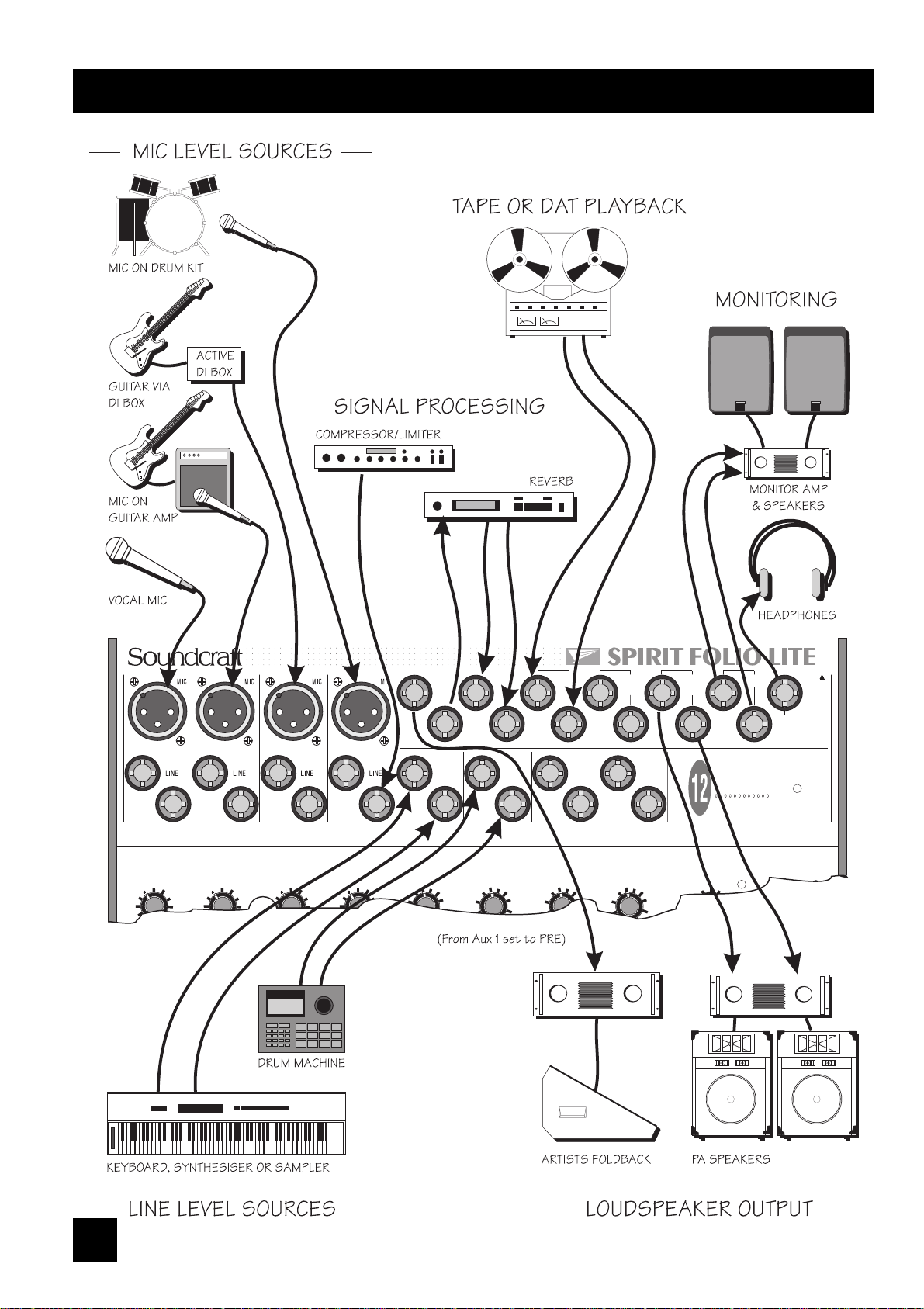
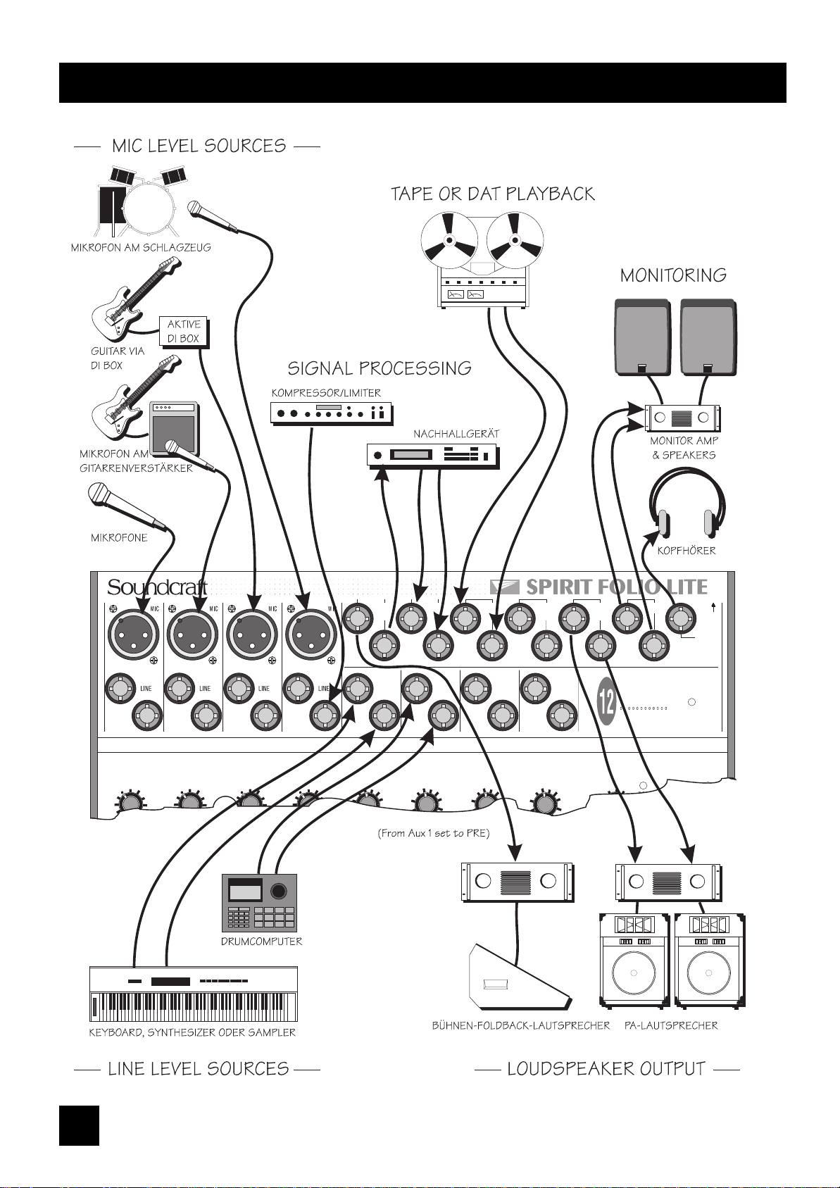
connecting it up
INSERT INSERT INSERT INSERT
15 151515
O/P
AUX
LEFT
GAIN GAINGAINGAIN
20dB 20dB20dB20dB
-10-10-10-10
-4-4-4-4
UUUU
-40-40-40-40
-60dBu-60dBu-60dBu-60dBu
0 000
-25-25-25-25
TRIMTRIMTRIMTRIM
5 555
10 101010
RIGHT
1
2
RIGHTRIGHT RIGHT
L
R
LEFT
L
RET
FX
LEFT
R
L
R
RET
2TRK
INS
M
IX
4
0
1
2
3
5
6
10
9
8
7
FX RET
4
0
1
2
3
5
6
10
9
8
7
PSU
2TRK
PHANTOM
48V
O/P
LEFT
L
R
L
R
IX
M
PSU
PHONES
NTR
M
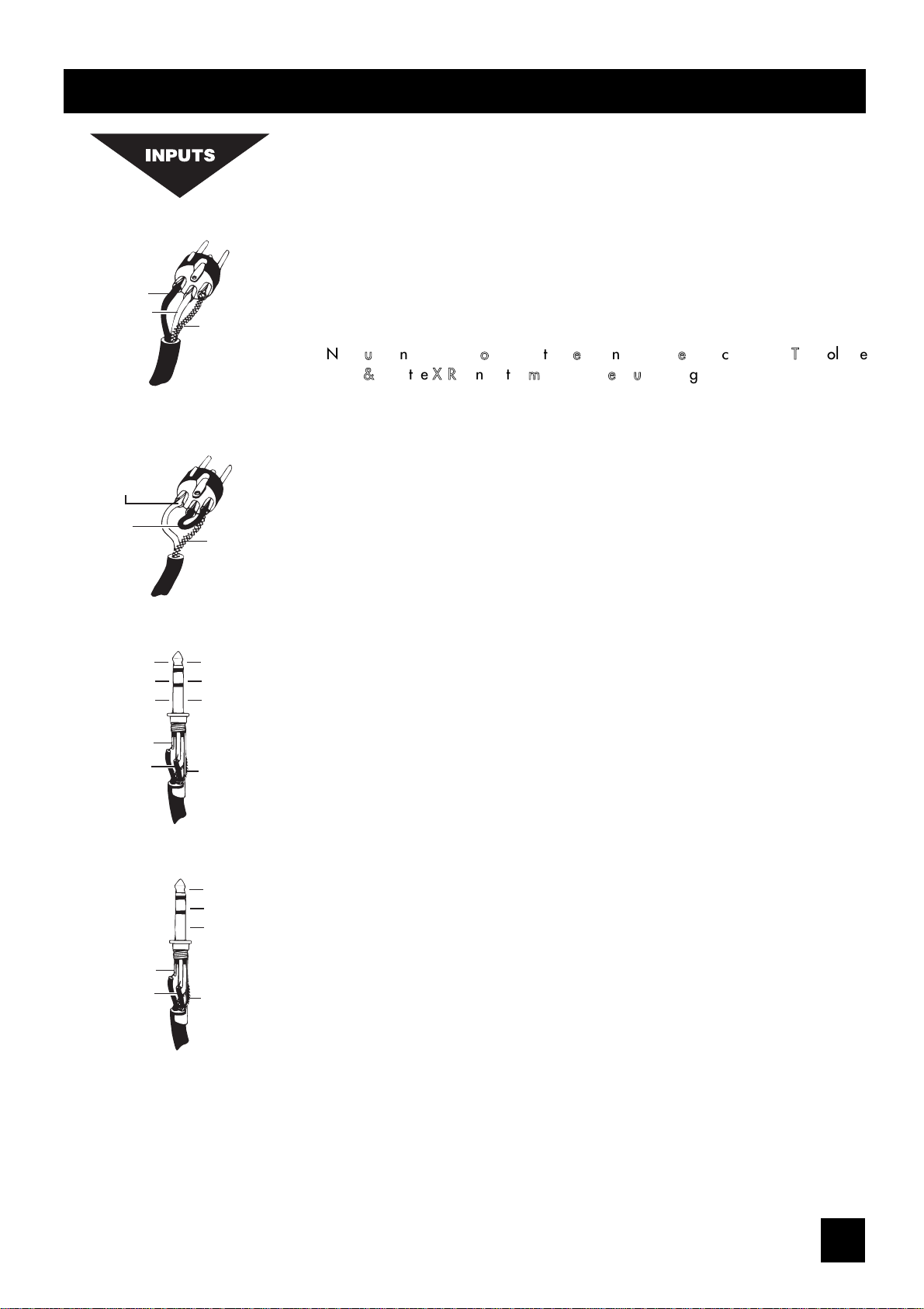
INPUTS
33
WIRING IT UP
Signal Send
Signal Return
Gnd/Screen
Tip
Ring
Sleeve
Inserts
Hot (+ve)
Cold (-ve)
Gnd/Screen
Signal
Gnd/Screen
Gnd/Screen
Tip
Ring
Sleeve
Unbalanced
3 pole Jack
Unbalanced Mic
XLR
Balanced Mic
XLR
Balanced
3 pole Jack
2. Hot(+ve)
3. Cold(-ve)
1. Screen
1. Screen
2. Hot(+ve)
Link 3
to 1
MIC INPUT
The mic input accepts XLR-type connectors and is designed to suit a wide range of
BALANCED or UNBALANCED low-level signals, whether from delicate vocals requiring
the best low-noise performance or close-miked drum kits needing maximum headroom.
Professional dynamic, condenser or ribbon mics are best because these will be LOW
IMPEDANCE. While you can use low-cost HIGH IMPEDANCE mics, you do not get the
same degree of immunity to interference on the microphone cable and as a result the
level of background noise may be higher. If you turn the PHANTOM POWER on (top
right-hand side of the mixer) the socket provides a suitable powering voltage for
professional condenser mics.
DDOO
NNOOTT
uussee
uunnbbaallaanncceedd
ssoouurrcceess
wwiitthh
tthhee
pphhaannttoomm
ppoowweerr
sswwiittcchheedd
oonn..
TThhee
vvoollttaaggee
oonn
ppiinnss
22
&&
33
ooff
tthhee
XXLLRR
ccoonnnneeccttoorr
mmaayy
ccaauussee
sseerriioouuss
ddaammaaggee..
Unplug any mics if you want to use the corresponding LINE Input to avoid the load
presented by the mic from affecting the Line Input gain. The input level is set using the
TRIM knob.
LINE INPUT
Accepts 3-pole `A gauge (TRS) jacks, or 2-pole mono jacks which will automatically
ground the 'cold' input. Use this input for sources other than mics, such as keyboards,
drum machines, synths, tape machines or guitars. The input is BALANCED for low
noise and immunity from interference, but you can use UNBALANCED sources by
wiring up the jacks as shown below, although you should then keep cable lengths as
short as possible to minimise interference pick-up on the cable. Note that the ring must
be grounded if the source is unbalanced. Unplug anything in the MIC input if you
want to use this socket. Set the input level using the TRIM knob.
INSERT POINT
The unbalanced, pre-EQ insert point is a break in the channel signal path, allowing
limiters, compressors, special EQ or other signal processing units to be added in the
signal path. The Insert is a 3-pole 'A' gauge jack socket which is normally bypassed.
When a jack is inserted, the signal path is broken, just before the EQ section.
The signal from the channel appears on the TIP of the plug and is returned on the
RING.
STEREO INPUTs
Accept 3-pole `A gauge (TRS) jacks, or 2-pole mono jacks which will automatically
ground the 'cold' input. Use these inputs for sources such as keyboards, drum
machines, synths, tape machines or as returns from processing units. The input is
BALANCED for low noise and immunity from interference, but you can use
UNBALANCED sources by wiring up the jacks as shown below, although you should
then keep cable lengths as short as possible to minimise interference pick-up on the
cable. Note that the ring must be grounded if the source is unbalanced. Mono sources
can be fed to both paths by plugging into the Left jack only.
FX RETURNS
Similar to the Stereo Inputs, except that they are unbalanced. Input gain is sufficient to
allow the connection of +4dBu professional or -10dBV semi-professional equipment.
44
Left Signal
Right Signal
Ground
Headphones
Signal (+ve)
Ground Sense (-ve)
Screen
Signal (+ve)
Gnd/Screen
Gnd/Screen
Signal Send
Signal Return
Gnd/Screen
Tip
Ring
Sleeve
Mix Inserts
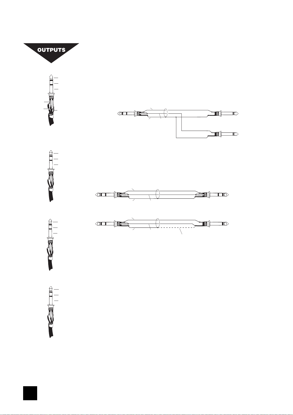
Mix Outputs
Aux Outputs
Monitor Outputs
Mix INSERTS
The unbalanced, pre-fade Mix insert point is a break in the output signal path to allow
the connection of, for example, a compressor/limiter or graphic equaliser. The Insert is
a 3-pole 'A' gauge jack socket which is normally bypassed. When a jack is inserted,
the signal path is broken, just before the mix fader.
The mix signal appears on the TIP of the plug and is returned on the RING. A 'Y' lead
may be required to connect to equipment with separate send and return jacks as shown
below:
MONITOR OUTPUTS
The Monitor outputs are unbalanced on 3-pole 'A' gauge jacks, wired as shown. The
outputs are automatically cut off if a jack is inserted in the PHONES socket.
HEADPHONES
The PHONES output is a 3-pole 'A' gauge jack, wired as a stereo output as shown,
suitable for headphones of 200W or greater, although impedances as low as 50W will
operate satisfactorily. 8W headphones are not recommended. Inserting a jack
automatically cuts off the Monitor outputs (see above), which are restored when the
PHONES jack is removed. This allows a self-operator to continue monitoring while
making voice recordings without having to turn the power amplifiers down.
GROUNDING CONSIDERATIONS
The power supply does not provide the mixer with any direct connection to mains
ground, and therefore some care must be taken to ensure that a ground connection is
made at an appropriate point in the system. In PA systems the most suitable point
would be to ground through the Mix Outputs into the power amp leads. In a studio set-
up the Monitor Outputs would provide a suitable connection via the monitor power
amp leads.
(a) Balanced Connection
To External Device
Hot
Hot
Screen
Screen
Ground Sense
Ground Sense
Experience has shown that sometimes it is better
not to connect screen at external device end.
From FOLIO LITE
Ground Compensated
Output
From FOLIO LITE
Ground Compensated
Output
To External Device
(b) Unbalanced Connection
Send to External Device
Signal Send
Screen
Signal Return
Insert Point
Return from External Device
MIX OUTPUTS, AUX OUTPUTS
The Mix and Aux outputs are on 3-pole 'A' gauge jack sockets, wired as shown on the
left and below, and incorporate ground compensation which helps to avoid ground
loops and their associated hums and buzzes when feeding into unbalanced equipment.
55
INITIAL setting up
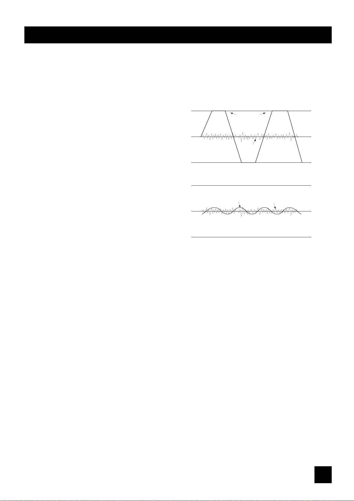
You will probably use your SPIRIT FOLIO LITE with a wide range of different types of sound source, and these will be at
varying signal levels. The mic amp has been designed with a particularly wide gain range, but it is important to set the
TRIM control correctly to give the best performance. If the input level is too high the signal will distort as it overloads the
channel and causes clipping. If it is too low the level of any background hiss will be more noticeable and you may not be
able to get enough signal level to the output of the mixer. This is illustrated in the diagram below.
Set up the individual mono input channels as follows:
o Plug in the chosen source (usually the MIC input for
mics and the LINE input for anything else). Plug in
phantom powered mics before switching the
phantom power on.
o Set the rotary Mix Fader on the Master section fully
anticlockwise. Press the PFL switch on the Master
section to route PFL to the monitor and meters.
o Provide the chosen source with a typical signal level
and press the PFL button by the fader. The level of
signal will be shown on the Bargraph Meters.
o Adjust the input TRIM until the meter is just reaching
the amber LED (0dB) at a typical maximum source
level with a steady signal. If the source signal is rich
in high-level transients (e.g. drums) a rather higher
meter reading of +6/+9 will be needed to achieve
an equivalent average level. This leaves enough
headroom to cope with peaks in the signal without
distortion.
o Adjust each mono input channel in the same way.
o If you find that you cannot set a reasonable level within the range of the TRIM control when using a MIC input, try the
LINE input instead.
The Stereo inputs can be set up in a similar way. Start with the GAIN control anticlockwise, which will suit inputs from
professional equipment with a +4dBu output. A higher GAIN setting will be needed for semiprofessional sources which
typically have -10dBV output level.
You will now have initial settings for each of the input sources and are ready to start building a mix.
o Connect your power amplifiers and speakers and set the gain of the amplifiers to about 70%. Set the Master Fader
fully clockwise, listening carefully for any hint of feedback or overload. You may find that the input fader settings will
need to be edged back slightly as the mix is built up.
o Listen carefully for the characteristic sound of `feedback. If you cannot achieve a satisfactory input level setting
without feedback, adjust microphone and speaker positions and try again.
Careful microphone placement and the choice of a suitable type of microphone is essential for successful PA use. The aim
should be to place the microphone as close as possible to the source, to cut out unwanted surrounding sounds. This allows
a lower gain setting on the mixer and helps to avoid feedback. You will also find that a well-placed microphone will not
need any appreciable equalisation.
If the signal level is too low it may be masked
by the noise.
Signal
Noise
If the signal level is too high, clipping distortion
may occur.
Clipped
Signal
Noise

66
The inherent low noise of the input channels on FOLIO LITE allows an alternative method of setting-up, which allows the
use of the optimum range of the input faders.
o Set the Master Fader fully clockwise.
o Set all input faders to the '0' mark. Note that this still allows 10dB of gain in hand.
o Gradually bring up each channel by adjusting the input TRIM control until the required mix is created.
SETTING UP FOR RECORDING
While the connections to the FOLIO LITE for PA work are quite straightforward, recording is rather more demanding
because the mixer is not only required to mix down input signals but also to provide a monitor mix for artists to hear. The f
following describes a typical set-up for recording two tracks on a multitrack recorder, but would be similar for a 2-Track
machine:
o Connect input sources and set gain as described opposite. Connect Mix Left & Right outputs to the multitrack tape
inputs.
o Route the channel signal to the required tape input by setting the PAN fully left or right. For example, panning fully
left will route the signal from the Left Mix output only. This allows an individual source to be sent to an individual tape
track.
o Connect the multitrack tape outputs to the 2 Track Returns. Set the 2TRK LEVEL control fully clockwise for -10dBV
sources, or at a lower setting for equipment with a higher output level.
o Connect a monitor amplifier for foldback headphones or a monitor speaker to the Aux 1 output. Set the amplifier
volume to a normal listening level. Press the AUX 1 PRE switch on the Master section to set all channel Aux 1 sends to
pre-fade.
o Use the Aux 1 send controls on the input channels to set up a mono monitor mix. (make sure that all other Aux 1
controls are fully off)
o If a compressor is to be used, connect this to the Mix Insert points.
o Connect any effects required using Aux 2, and return them to the mixer on unused Line or Stereo inputs or FX Return
to allow the effect to be balanced with the original source.
If it is necessary to hear the off-tape signal as part of the foldback mix, for instance for overdubbing, connect the tape
outputs to unused stereo or line inputs, which can access the Aux 1 send.
It is important to match the input and output levels of your mixer and recording device to avoid distortion and create the
best recording.
o Set the recording level as recommended for your recording device, feeding a suitable signal from the Mix outputs.
With MONITOR SOURCE selected to MIX the meters will display the signal being fed to the recorder.
o Monitor the signal going to the recorder by selecting 2TRK on the MONITOR SOURCE switch. Gradually increase the
2TRK level while toggling the MONITOR SOURCE switch to alternate between the Mix output and 2TRK return until no
change in level is audible or visible on the LED meters.
77
15
6
9
12
3
15
3
6
12
9
- +
0
8
10dB
2
2
1
0
1
5
4
5
4
3
3
4
0
1
2
3
5
6
10
9
8
7
4
0
1
2
3
5
6
10
9
8
7
FADER
0
PAN
AUX
2
AUX
1
15
6
9
12
3
15
3
6
12
9
- +
0
-10
-4
U
-40
LF
-60dBu
HF
-25
TRIM
mono input
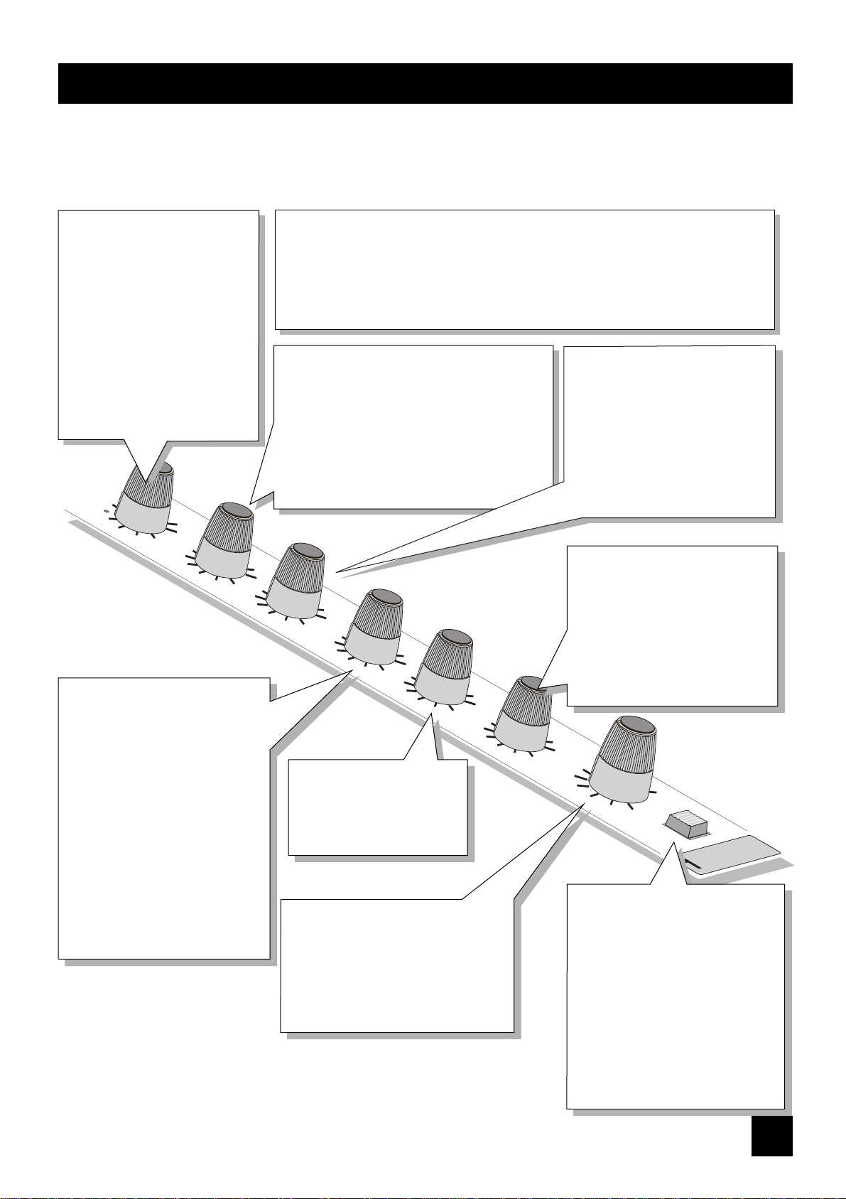
FOLIO LITE has 4 Mono input channels, each with balanced inputs for microphone and line level sources, and an Insert
point to allow the signal to be taken out of the mixer, through an external piece of equipment and then back into the mixer
to continue through to the final output. The Insert point comes before the EQ and allows limiters, compressors and other
signal processing units to be added as required to particular channels.
TRIM
This knob sets how much of the
source signal is sent to the rest of
the mixer. Adjust it carefully -too
high and the signal will overload
and distort, too low, and the level
of any background hiss will be
more noticeable and you may not
be able to get enough signal level
to the output of the mixer.
The 'U' mark gives a nominal
unity gain for the Line input.
EQUALISER
The Equaliser (EQ) gives fine control over the signal quality, particularly to improve the
sound in live PA applications where the original signal is often far from ideal.
The EQ knobs can have a dramatic effect on the sound, so use them sparingly and listen
carefully to the result.
HF EQ
Turn to the right to boost high (treble) frequencies
by up to 15dB at 12kHz, adding crispness to
cymbals, vocals and electronic instruments. Turn
to the left to cut these frequencies, reducing hiss
or distorted consonants which can occur with
certain types of microphone. Set the knob in the
centre-detented position when not required.
AUX SEND 1
This is used to set up a separate mix
for FOLDBACK, EFFECTS or
recording, and the combination of
all the Aux 1 Sends is mixed to the
Aux 1 Output. For Effects it is useful
for this to fade up and down with
the FADER (this is called POST-
FADE), but for Foldback or Monitor
feeds it is important for the send to
be independent of the FADER (this is
called PRE-FADE). The Master
Section AUX1 PRE switch allows you
to chose pre- or post-fade as
required. Leave the knob turned
down when not in use.
AUX SEND 2
This is similar to the Aux Send
1 control, but is always POST-
FADE.
PAN
This control sets the amount of the
channel signal feeding the Right and
Left MIX outputs, allowing you to
move the source smoothly across the
stereo image. When the control is
turned fully right or left the signal is
sent only to that side of the mix.
FADER
The rotary FADER gives you smooth
control of the overall signal level in the
channel strip, allowing precise balancing
of the various source signals being
mixed to the Master Section.
PFL
When the PFL (Pre-Fade-Listen) switch
is pressed the pre-fade signal is fed to
both sides of the Monitor. It may be
heard on headphones or the monitor
output and shown on the meters if the
Master section PFL switch is pressed.
You use this switch to listen to a
channel signal without affecting the
mixer outputs, to check the signal
quality, set the input TRIM, or simply
to check that it is there!
LF EQ
Turn to the right to boost low (bass)
frequencies by up to 15dB at 60Hz,
adding warmth to vocals or extra
punch to synths, guitars and drums.
Turn to the left to reduce hum, stage
rumble or improve a mushy sound.
Set the knob to the centre-detented
position when not required.
88
15
6
9
12
3
15
3
6
12
9
- +
0
FADER
10dB
2
2
1
0
1
5
4
5
4
3
3
BAL
AUX
AUX
4
0
1
2
3
5
6
10
9
8
7
4
0
1
2
3
5
6
10
9
8
7
8
0
2
1
15
15
6
9
12
3
15
3
6
12
9
- +
0
GAIN
20dB
0
5
10
LF
HF
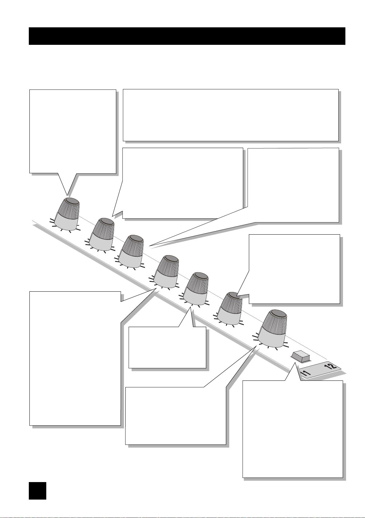
stereo input
FOLIO LITE has 4 Stereo input channels, suitable for a wide variety of line level sources, such as keyboards, drum
machines, synths or tape machines. The inputs are balanced for low noise and immunity from interference, but you can
use unbalanced sources (see 'Connections' for wiring details), although you should then keep cable lengths as short as
possible to minimise interference pick-up.
GAIN
This knob allows you to match the
input level to suit a wide variety of
profesional, semi-professional and
hi-fi sources.
Start with a low setting, especially
for professional equipment, and
increase it if you cannot reach an
adequate signal levelwith the fader
at maximum.
EQUALISER
The Equaliser (EQ) gives fine control over the signal quality, to minimise background
noise, or to alter the character of synthesised voices from electronic instruments.
The EQ knobs can have a dramatic effect on the sound, so use them sparingly and listen
carefully to the result.
HF EQ
Turn to the right to boost high (treble)
frequencies by up to 15dB at 12kHz, adding
crispness to percussion from drum machines,
synths and electronic instruments. Turn to the left
to cut these frequencies, reducing hiss or
excessive brillinace. Set the knob in the centre-
detented position when not required.
AUX SEND 1
This is used to set up a separate
mono mix for FOLDBACK or to drive
EFFECTS processors, and the
combination of all the Aux 1 Sends
is mixed to the Aux 1 Output. For
Effects it is useful for this to fade up
and down with the FADER (this is
called POST-FADE), but for
Foldback or Monitor feeds it is
important for the send to be
independent of the FADER (this is
called PRE-FADE). The Master
Section AUX1 PRE switch allows you
to chose pre- or post-fade as
required. Leave the knob turned
down when not in use.
AUX SEND 2
This is similar to the Aux Send
1 control, but is always POST-
FADE.
LF EQ
Turn to the right to boost low (bass)
frequencies by up to 15dB at 60Hz,
adding extra punch to synths,
guitars and drums. Turn to the left to
reduce hum, boominess or improve
a mushy sound. Set the knob to the
centre-detented position when not
required.
BALANCE
This control sets the amount of the
channel signal feeding the Right and
Left MIX outputs, allowing you to
balance the source in the stereo
image. When the control is turned
fully right or left you feed only that
side of the signal to the mix.
FADER
The rotary FADER gives you smooth
control of the overall signal level in the
channel strip, allowing precise balancing
of the various source signals being
mixed to the Master Section.
PFL
When the PFL (Pre-Fade-Listen) switch is
pressed the pre-fade channel signal is
fed in stereo to the Monitor. It may be
heard on headphones or the monitor
output and shown on the meters if the
Master section PFL switch is pressed.
You use this switch to listen to a channel
signal without affecting the mixer
outputs, to check the signal quality, set
the input TRIM, or simply to check that it
is there!
99
IX FADER
M
8
0dB
MONITOR
0
1
9
10
PFL
-10
LEFT
AUX1
REF +4dBu
PRE
PST
4
3
2
-20
5
-10
-15
-3
-6
6
8
7
SOURCE
MONITOR
3
0
9
6
RIGHT
12
4
0
1
2
3
5
6
10
9
8
7
IX
M
FX RET
4
0
1
2
3
5
6
10
9
8
7
PSU
2TRK
2TRK TO
2TRK
M
IX
M
IX
PHANTOM
48V
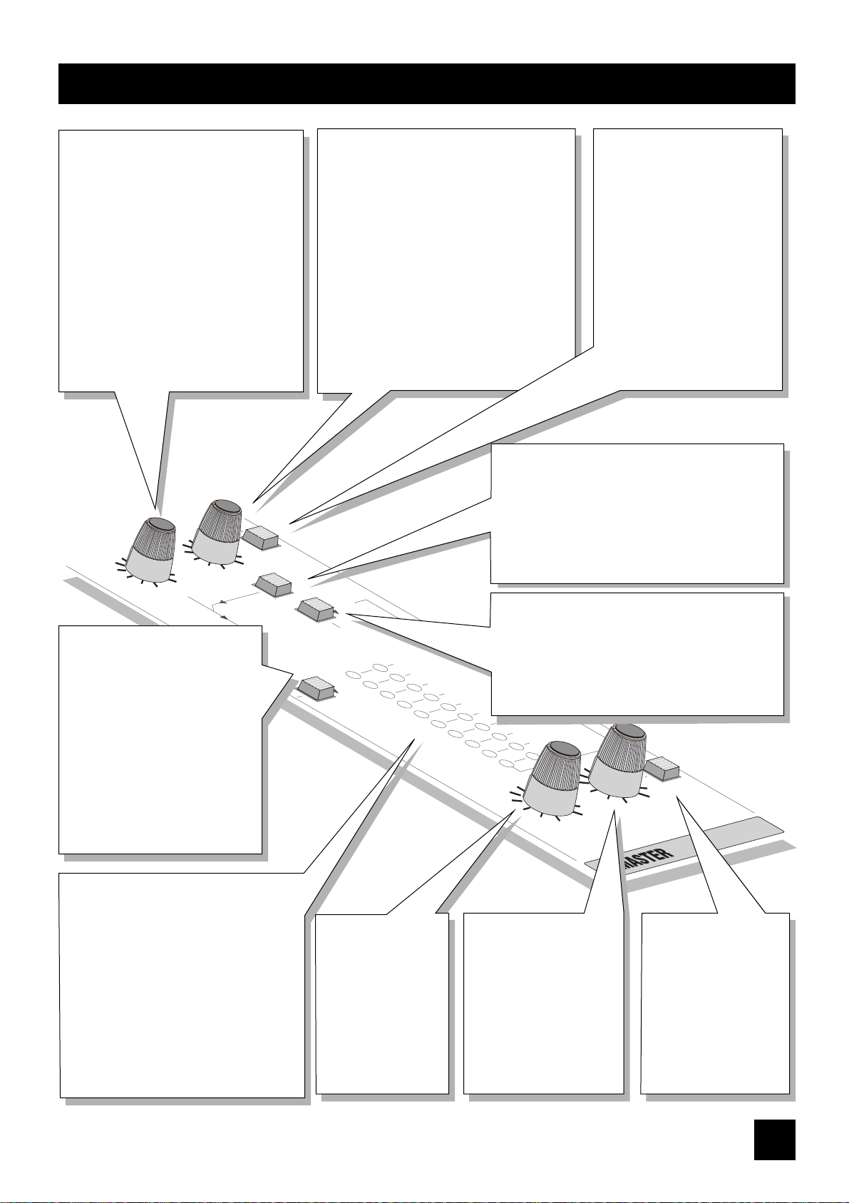
master section
FX RETURN
The unbalanced FX Returns are an ideal
place to connect the output of an EFFECTS
unit, without using up any of the LINE
inputs.
The control sets the level of signal fed
directly to the MIX. When set fully
clockwise the inputs will be matched to
-10dBV (semi-professional) sources, or
will suit +4dBu sources with the control at
a lower setting.
A mono source, plugged into the LEFT
jack only is fed to both sides of the MIX.
2TRK (2 TRACK)
The unbalanced 2TK returns are an ideal
place to connect the playback of a tape
machine, without using up any of the LINE
inputs.
The control sets the level of signal fed directly
to the MIX. When set fully clockwise the
inputs will be matched to -10dBV (semi-
professional) sources, or will suit +4dBu
sources with the control at a lower setting.
A mono source, plugged into the LEFT jack
only is fed to both sides of the MIX.
2TRK TO MIX
Press this switch to route the 2TK Return signal to the
MIX outputs giving you two extra inputs at
mixdown. Adjust the level with the 2TRK control.
Overall level will be set by the MIX FADER.
DO NOT PRESS THIS SWITCH WHEN RECORDING
or load feedback will occur and ruin the recording.
MONITOR SOURCE
This switch selects the source for the Monitor outputs
or Headphones. When released the source is the
MIX, when pressed it becomes the 2 Track Return
signal. Note that the selected source is replaced by
PFL if the the PFL switch is pressed.
AUX 1 PRE
Press this switch to make all of the
AUX 1 sends on the input
channels PRE-FADE. This means
that they will all be unaffected by
channel fader position, making
them ideal for FOLDBACK or
MONITORING.
When the switch is released the
AUX 1 sends are all POST-FADE,
and will fade up and down with
the channel faders.
BARGRAPH METERS
The three-colour, peak-reading
BARGRAPH METERS show the level of the
selected monitor source (MIX, 2TRK or
PFL) to give a warning of excessive peaks
in the signal which might cause
overloading.
With the Master Fader at 0dB, aim to
keep the signal just touching the amber
segments, with a steady signal, or up to
+6/+9 on peaky signal sources such as
drum beats.
PFL
Pressing this switch replaces
the selected monitor source
with the stereo PFL signal
(mono from mono input
channels).
Releasing the switch returns
the monitor to the
previously selected source.
MONITOR
This control sets the output
level to the MONITOR LEFT
& RIGHT outputs.
If HEADPHONES are
plugged into the PHONES
jack the monitor outputs are
cut off, and the knob then
sets the headphone level.
PHANTOM 48V
This switch turns on the 48V
PHANTOM POWER to the mic
inputs, sending a powering
voltage down the same wires as
the signal to suit many
professional condenser mics.
DO NOT turn on the phantom
power when using unbalanced
mics which may be damaged
by the voltage.
Note: Mics should always be
plugged in before switching the
Phantom Power ON.
MIX FADER
The MIX FADER sets
the final level of the
MIX outputs. The
fader should normally
be set close to the
'0dB' mark if the input
levels have been set
correctly.
1100
Mix Noise
Input faders down, Master Faders up < -81dBu
Aux Noise Input Sends down < -88dBu
E.I.N. Source resistance 150, -128dBu
Distortion Mic Gain 30dB, Mix Out at +14dBu <0.007% @ 1kHz
Crosstalk (measured at 1kHz sine wave)
Input Fader Attenuation >85dB
Aux Send Attenuation >84dB
Adjacent Channel >90dB
Stereo Separation >75dB
Frequency Response 20Hz- 30kHz, relative to 1kHz +/- 1dB
C.M.R.R. Mono Input at max. gain, measured @ 1kHz 85dB
Stereo Input at any gain 50dB
Input & Output Impedances
Mic Inputs 2kW
Line Inputs 10kW
Outputs 75W
Input & Output Levels Mic Input max. level +16dBu
Line Input max. level >+30dBu
Any Output max. level +21dBu
Headphone Output each side 130mW into 600W
Weight Console Power Pack
2.5Kg 0.6Kg
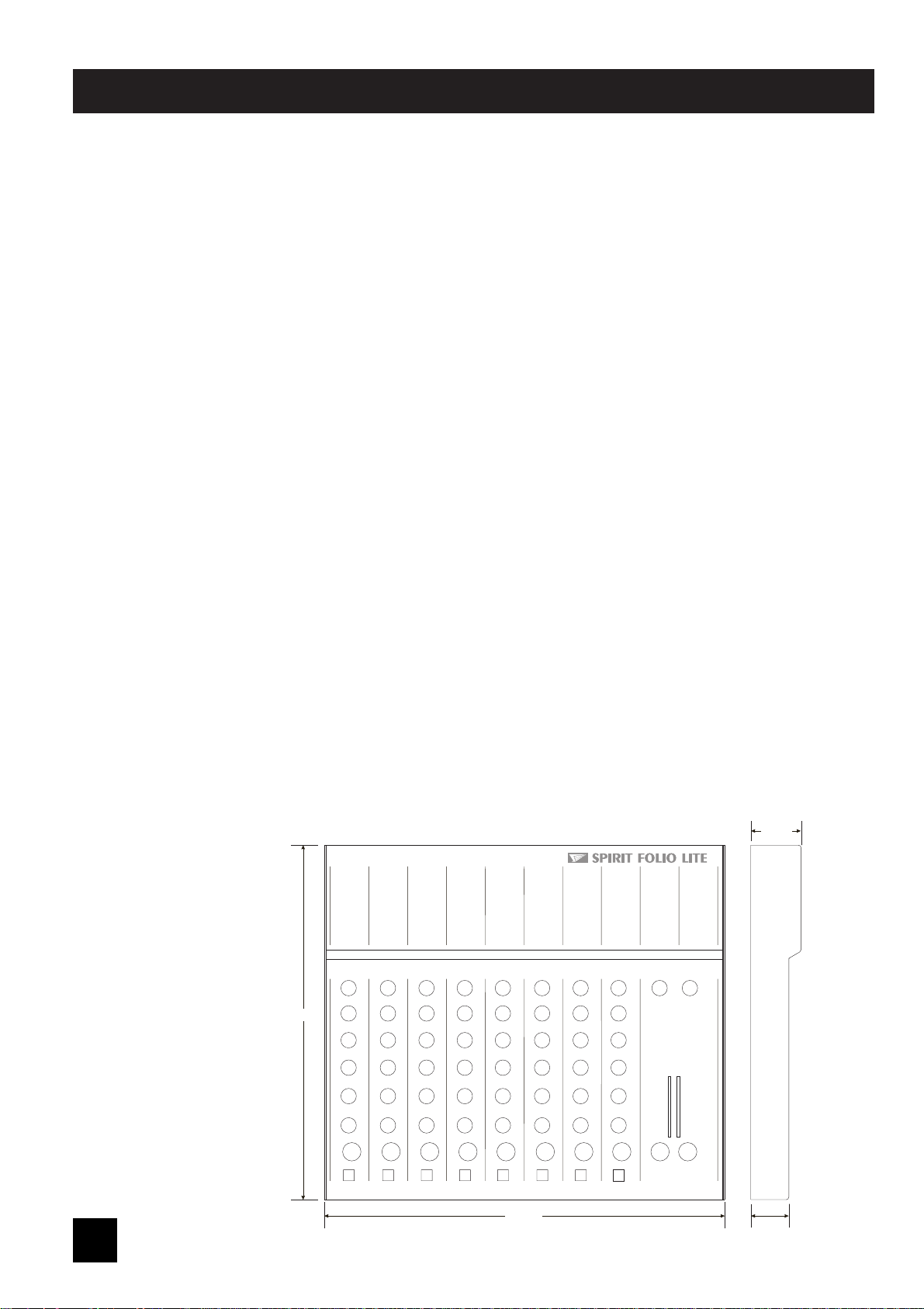
DIMENSIONS
All dimensions are
in millimetres
TYPICAL specifications
37.70
28.50
300.00
265.50

1111
glossary
AFL (After Fade Listen) a function that allows the operator to monitor the post-fade signal in a channel independently of the main mix.
Balance the relative levels of the left and right channels of a stereo signal.
Balanced a method of audio connection which `balances the signal between two wires and a screen which carries no
signal. Any interference is picked up equally by the two wires, but out of phase resulting in cancellation of the
interference signal.
Clipping the onset of severe distortion in the signal path, usually caused by the peak signal voltage being limited by the
circuits power supply voltage.
dB (decibel) a ratio of two voltages or signal levels, expressed by the equation dB=20Log<M>10 (V1/V2). Adding the
suffix u denotes the ratio is relative to 0.775V RMS.
DI (direct injection) the practice of connecting an electric musical instrument directly to the input of the
mixing console, rather than to an amplifier and loudspeaker which is covered by a microphone feeding
the console.
Effects the use of devices to alter or process the sound to add special effects e.g. reverb, normally as a mix of
the original (`dry) sound and the treated version.
Equaliser a device that allows the boosting or cutting of selected bands of frequencies in the signal path.
Feedback the `howling sound caused by bringing a microphone too close to a loudspeaker driven from its amplified
signal.
Foldback a feed sent back to the artistes via loudspeakers or headphones to enable them to monitor the sounds they are
producing.
Frequency response the variation in gain of a device with frequency.
Ground Compensation a technique used on unbalanced outputs to cancel out the effect of ground loops caused by connections
to external equipment.
Headroom the available signal range above the nominal level before clipping occurs.
Line level signals at a nominal level of -10 to +6dBu, usually coming from a low impedance source.
Peaking an equaliser response curve affecting only a band of frequencies i.e. based on a bandpass response.
PFL (pre-fade listen) a function that allows the operator to monitor the pre-fade signal in a channel independently of the main mix.
Phantom Power the +48V d.c. voltage applied equally to the two signal pins of a balanced mic input to provide powering for
condenser microphones.
Post-Fade the point in the signal path after the channel or master fader and therefore affected by fader position.
Processor a device which affects the whole of the signal passing through it, e.g. gate, compressor or equaliser
Rolloff a fall in gain at the extremes of the frequency response.
Signal to Noise Ratio a expression of the difference in level between the audio signal and background system noise.
Solo-in-Place a function that allows the operator to listen to a selected channel on its own but complete with all relevant
effects, by automatically muting all other inputs.
Talkback the operator speaking to the artistes or to tape via the auxiliary or group outputs.
Tape Return a line level input provided specifically to receive the playback output of a tape machine
Transient a momentary rise in the signal level.
TRS Jacks a 3-pole jack with Tip, Ring and Sleeve connections
Unbalanced a methode of audio connection which uses a single signal wire and the cable screen as the signal return.
This method does not provide the noise immunity of a balanced input (see above).
1122
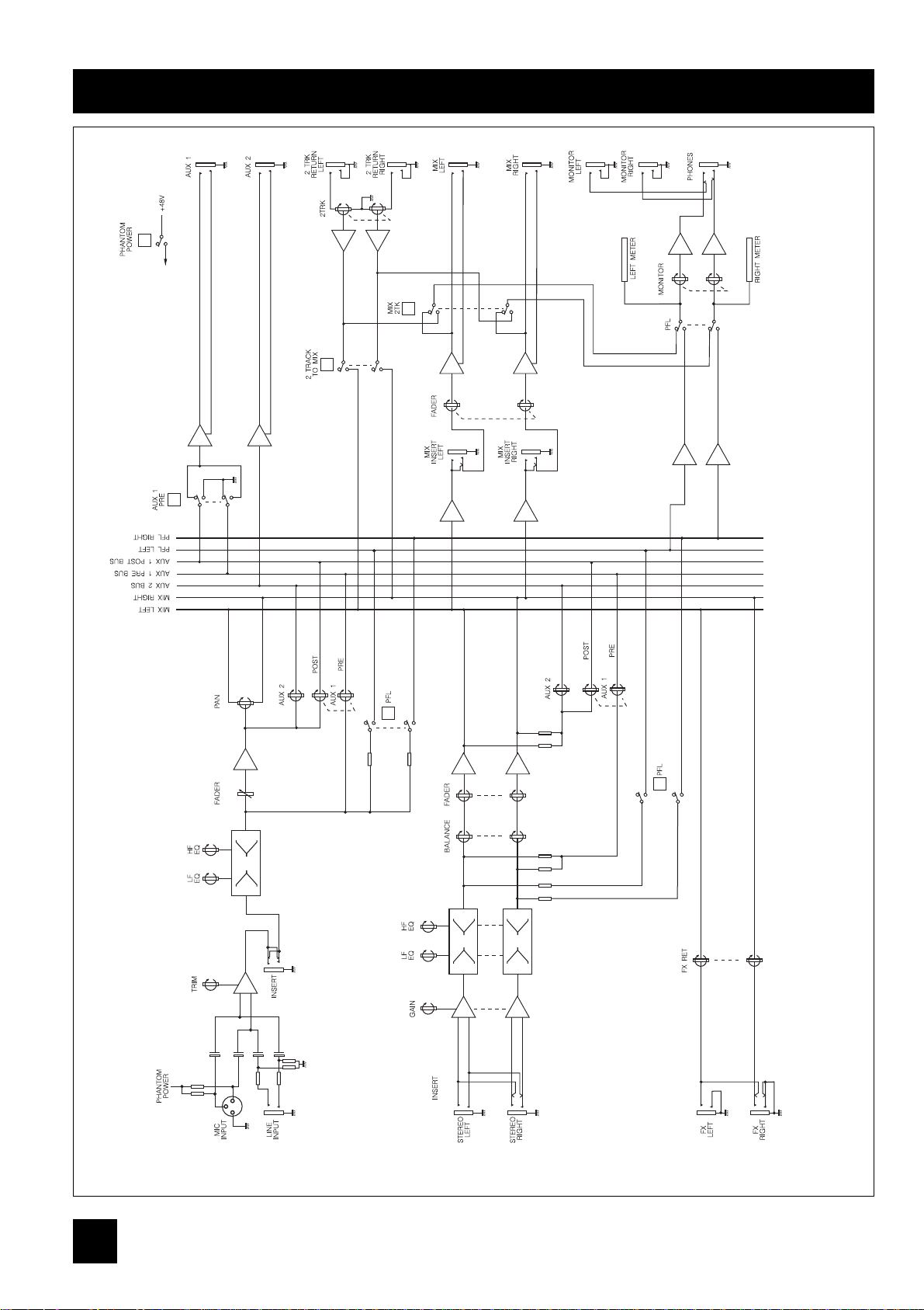
system block diagram
3
1
2
MONO INPUT CHANNEL
FX RETURN
STEREO INPUT
CHANNEL
MASTER SECTION
13
Wir hoffen, daß Sie genauso viel Spaß wie wir, das Spirit-Team, mit dem SPIRIT FOLIO LITE Mixer haben. Das SPIRIT
Team: Peter, Graham, Malcolm, Martin, Peter, Brian, George, Colin, Tony, James, Mukesh, Andy, Candy und Simon.
Mit dem Erwerb einer SPIRIT-Konsole erhalten Sie fachmännisches Geschick und Unterstützung von einem der führenden
Mischpult-Hersteller, wobei anzumerken ist, daß die über 20jährige Erfahrung von Soundcraft so manchem Großen in
Musikbranche bei der Musikproduktion erfolgreich half.
Um höchsten Standards zu entsprechen, werden im FOLIO LITE nur Qualitätsbauteile eingesetzt, die auch schon im
FOLIO 4 verwendet wurden. Mit dem FOLIO LITE haben wir ein Mischpult gebaut, daß ansprechend und einfach zu
bedienen ist. Dennoch sollten Sie dieses Handbuch lesen, damit Sie vertrauerter mit dem Mixer werden und eine Live-
Session Sie in keinster Weise aus der Fassung bringen kann. Letztendlich ist der SPIRIT Mixer konstruiert, um Ihre
musikalische Kreativität zu steigern. Je mehr Sie herausfinden, wie Sie die einzelnenen Bedienelemente einstellen können
und welchen Einfluß das auf den Sound hat, desto mehr Spaß haben Sie daran, wenn Sie wissen, wie Sie der
Endmischung den letzten Schliff geben können.
ZZuu
IIhhrreerr
eeiiggeenneenn
SSiicchheerrhheeiitt
uunndd
zzuurr
EEiinnhhaallttuunngg
ddeerr
GGaarraannttiiee
lleesseenn
SSiiee
bbiittttee
ddiieesseenn
AAbbsscchhnniitttt!!
AAnn
ddeenn
FOLIO LITE
MMiixxeerr
ddaarrff
nnuurr
ddaass
mmiittggeelliieeffeerrttee
NNeettzztteeiill
aannggeesscchhlloosssseenn
wweerrddeenn!!..
Die Verdrahtung der Hauptleitungen stimmen überein mit folgendem Farbcode:
Grün und gelb: Gehäuse-Schutzleiter
Blau: Mittelpunktsleiter
Braun: Phase
Falls diese Festlegung nicht mit der Belegung in Ihrer Steckkontakte in der Steckdose übereinstimmt, gehen Sie
folgendermaßen vor:
o Die grün/gelbe Leitung muß an den mit dem Erde-Symbol gekennzeichneten Steckkontakt angeschlossen werden.
Achten Sie auch bei einem Steckdosenwechsel den Farbcode an den Steckkontakten der Steckdose.
UUmm
ddiiee
BBrraannddggeeffaahhrr
aauusszzuusscchhlliieeßßeenn,,
bbeennuuttzzeenn
SSiiee
HHaauuppssiicchheerruunnggeenn,,
ddiiee
ddeenn
AAnnggaabbeenn
aauuff
ddeemm
NNeettzztteeiill
eennttsspprreecchheenn!!
DDaass
NNeettzztteeiill
bbeessiittzztt
kkeeiinnee
bbeennuuttzzeerrwwiicchhttiiggeenn
BBaauutteeiillee
uunndd
ddaarrff
nniicchhtt
ggeeööffffnneett
wweerrddeenn!!
EEvveennttuueellllee
EEiinnggrriiffffee
üübbeerrllaasssseenn
SSiiee
qquuaalliiffiizziieerrtteenn
FFaacchhlleeuutteenn
ooddeerr
ddeemm
SSoouunnddccrraafftt--HHäännddlleerr
iinn
IIhhrreerr
NNäähhee..
DEUTSCH - EINLEITUNG
SICHERHEIT
1144
AUFSTELLUNG
INSERT INSERT INSERT INSERT
15 151515
O/P
AUX
LEFT
GAIN GAINGAINGAIN
20dB 20dB20dB20dB
-10-10-10-10
-4-4-4-4
UUUU
-40-40-40-40
-60dBu-60dBu-60dBu-60dBu
0 000
-25-25-25-25
TRIMTRIMTRIMTRIM
5 555
10 101010
RIGHT
1
2
RIGHTRIGHT RIGHT
L
R
LEFT
L
RET
FX
LEFT
R
L
R
RET
2TRK
INS
M
IX
4
0
1
2
3
5
6
10
9
8
7
FX RET
4
0
1
2
3
5
6
10
9
8
7
PSU
2TRK
PHANTOM
48V
O/P
LEFT
L
R
L
R
IX
M
PSU
PHONES
NTR
M
INPUTS

1155
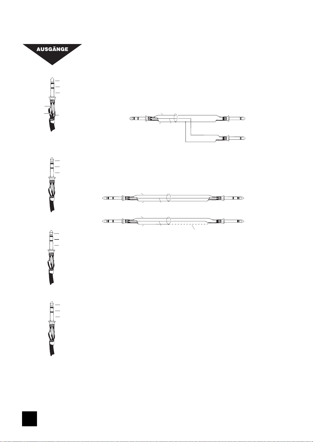
ANSCHLÜSSE
Signal Send
Signal Return
Schirm
Tip
Ring
Schirm
Inserts
Heiß (+ve)
Kalt (-ve)
Schirm
Signal
Schirm
Schirm
Tip
Ring
Schirm
3-polis
unsymmetrisch
Unsymmetrisch Mic
XLR
Symmetrisch Mic
XLR
3-polis
symmetrisch
2. Heiß(+ve)
3. Kalt(-ve)
1. Schirm
1. Schirm
2. Heiß(+ve)
1 zu 3
brücken
MIC EINGANG
Der Mic-Eingang ist mit XLR-Buchsen ausgestattet und kann niedrig-pegelige,
symmetrische wie unsymmetrische Signale verarbeiten. Zumeist sind das Vocals, die
absolut rauschfrei wiedergegeben werden sollen, oder nah abgenommene Drums, die
einen großen Aussteuerungsbereich benötigen. Dynamische, Kondensator- oder auch
Piezo-keramische Mikrofone sind als niederohmige Mikrofone bestens dazu geeignet.
Sie könnten auch preisgünstige, hochohmige Mikrofone verwenden, erhöhen jedoch
damit das Risiko für Rückkopplungen und andere Störeinstreuungen. Für professionelle
Kondensator-Mikrofone schalten Sie die Phantomspeisung (auf der rechten, oberen
Mixerseite) an.
Bei unsymmetrischen Signalquellen verwenden Sie bitte auf keinen Fall die
Phantomspeisung, da sonst Ihr Mischpult über die Stromführenden Pins (2&3)
beschädigt werden könnte.
Wenn Sie im Line-Kanal kein Mikrofon verwenden, so ziehen Sie dessen Stecker aus
der Buchse, damit keinerlei Störgeräusche in den Kanal gelangen können.
LINE EINGANG
Nimmt 3-polige Klinkenstecker, wie auch 2-polige Mono-Klinkenstecker auf, die
automatisch geerdet werden. Benutzen Sie diesen Eingang für alle anderen
Signalquellen wie Keyboards, Drum-Computer, Bandmaschinen oder Gitarren. Der
Eingang ist symmetrisch ausgelegt, um ein Höchstmaß an Rausch- und
Störgeräuschunterdrückung zu gewährleisten. Wenn Sie dennoch unsymmetrische
Kabel verwenden, dann sollten Sie möglichst kurze dazu gebrauchen. Beachten Sie
außerdem, daß der Ring geerdet sein sollte, wenn die Signalquelle unsymmetrisch
ist. Ziehen Sie nicht verwendete Mikrofonstecker aus der Buchse, wenn Sie den Line-
Eingang benutzen und stellen den Pegel für das Signal mit dem TRIM-Poti ein.
INSERT (Einschleifpunkt)
Der unsymmetrische, pre-EQ (vor der EQ-Sektion) Einschleifpunkt, unterbricht den
Signalfluß im Kanal, um dort Limiter, Kompressoren, Equalizer oder ähnliche
Signalprozessoren hinzuzufügen. Die zugehörige Buchse ist 3-polig und führt solange
kein Signal, bis eine externe Quelle angeschlossen wird. Das Signal wird aus dem
Kanal über den TIP herausgeführt und kehrt über den Ring wieder zurück.
STEREO-EINGÄNGE
Nimmt ebenfalls 3-polige Klinkenstecker wie auch 2-polige Mono-Klinkenstecker auf,
die automatisch geerdet werden. Verwenden Sie diese Anschlüsse um Keyboards,
Drum-Computer, Bandmaschinen anzuschließen, oder als Rückführwege für
Effektsignale. Auch dieser Eingang ist symmetrisch ausgelegt, damit Sie rauschfreie
Signale erhalten. Bei unsymmetrischen Quellen beachten Sie bitte die Pinbelegungen in
der unteren Abbildung und verwenden möglichst kurze Kabellängen. Beachten Sie,
daß der Ring geerdet sein muß, wenn Sie unsymmetrische Quellen anschließen.
Mono-Signalquellen können in beide Signalwege gespeist werden, wenn Sie nur die
linke Eingangsbuchse benutzen.
FX-RETURNS (Effekt-Rückführwege)
Wie die Stereoeingänge, nur unsymmetrisch ausgelegt. Die Eingangsverstärkung kann
füe Signalquellen zwischen +4 dB (professionell) und -10 dB (semi-professionell) justiert
werden.
1166
Linkes Signal
Rechtes Signal
Schirm
Kopfhörer
Signal (+ve)
Ground Sense (-ve)
Schirm
Signal (+ve)
Svhirm
Schirm
Signal Send
Signal Return
Schirm
Tip
Ring
Schirm
Mix Inserts
Mix Ausgänge
Aux Ausgänge
Monitor Ausgänge
MIX-INSERTS
Über diese Einschleifpunkte, die unsymmetrisch ausgeführt sind, können Konpressoren/
Limiter oder grafische Equaliser in die Mischpultsumme eingeschleift werden. Die 3-
polige Klinkenbuchse führt solange kein Signal, bis ein Stecker eingeführt wird, der den
Signalfluß im Kanal vor dem Mix-Fader unterbricht. Das Mix-Signal verläßt den Kanal
über den TIP des Steckers und kehrt über den RING wieder zurück. In der Grafik sehen
Sie die Konfektion eines Y-Kabels, daß verwendet wird, um externes Equipment
durch separate Sende- und Rückführstecker anzusteuern.
MONITOR-AUSGÄNGE
Die Monitor-Ausgänge sind, wie in der Grafik gezeigt, 3-polig unsymmetrisch
ausgeführt. Das hier anliegende Signal wird automatisch unterbrochen, wenn ein
Kopfhörer an die Headphones-Buchse angeschlossen ist.
HEADPHONES (Kopfhörer)
Sehen Sie sich zur Pinbelegung der Stereo-Buchse die abgebildete Grafik an. Hier
können Kopfhörer mit 200 Ohm oder mehr angeschlossen werden, obwohl die
Impedanz bei 50 Ohm liegt. Kophörer mit 8 Ohm sind nicht notwendig. Stecken Sie
hier einen Klinkenstecker ein, dann wird der Monitorweg automatisch unterbrochen. Im
Ein-Mann-Betrieb kann das zuweilen von Vorteil sein, da nicht erst die
Monitorendstufen leiser gedreht werden müssen, wenn z.B. Vocals aufgenommen
werden sollen.
ERDUNGS-HINWEISE
Das Netzteil versorgt das Mischpult nicht mit einem Erdungspunkt über den
Netzanschluß. Es ist deswegen nötig einen entsprechenden Erdungspunkt im System zu
verwenden. Bei PA´s ist es am sinnvollsten, die Erdung über die Summenausgänge vom
Mischpult, die mit den Endstufen verbunden sind, vorzunehmen. Im Studio kann diese
Erdung z.B. über die Monitor-Endstufen erfolgen, die mit dem Monitor-Ausgang
verbunden sind.
(a) Symmetrisch Connection
Zu Externem Gerät
Heiß
Heiß
Schirm
Schirm
Ground Sense
Ground Sense
Erfahrungs gemäß ist es besser, den schirm
nicht anzuschließen
From FOLIO LITE
Ground Compensated
Output
From FOLIO LITE
Ground Compensated
Output
Zu Externem Gerät
(b) Unsymmetrisch Connection
Zu Externem Gerät
Signal Send
Schirm
Signal Return
Insert Point
Von Externem Gerät
MIX-AUSGÄNGE, AUX-AUSGÄNGE
Sowohl die Mix- als auch Aux-Ausgänge sind als 3-polige Klinkenbuchsen ausgelegt
und zusätzlich ground compensated, was Brummschleifen und sonstige
Störeinstreuungen unterbindet.
1177
ANFANGS-EINSTELLUNGEN
Höchtswahrscheinlich möchten Sie unterschiedlichste Klangquellen an den SPIRIT FOLIO LITE Mixer anschließen. Um
bestmögliche Klangeinstellungen zu erhalten, ist es äußerst wichtig, die Vorverstärkung (GAIN) der Eingänge korrekt
einzustellen.Wenn Sie die Verstärkung zu gering einstellen, so sind Hintergrundgeräusche hörbar, und außerdem ist der
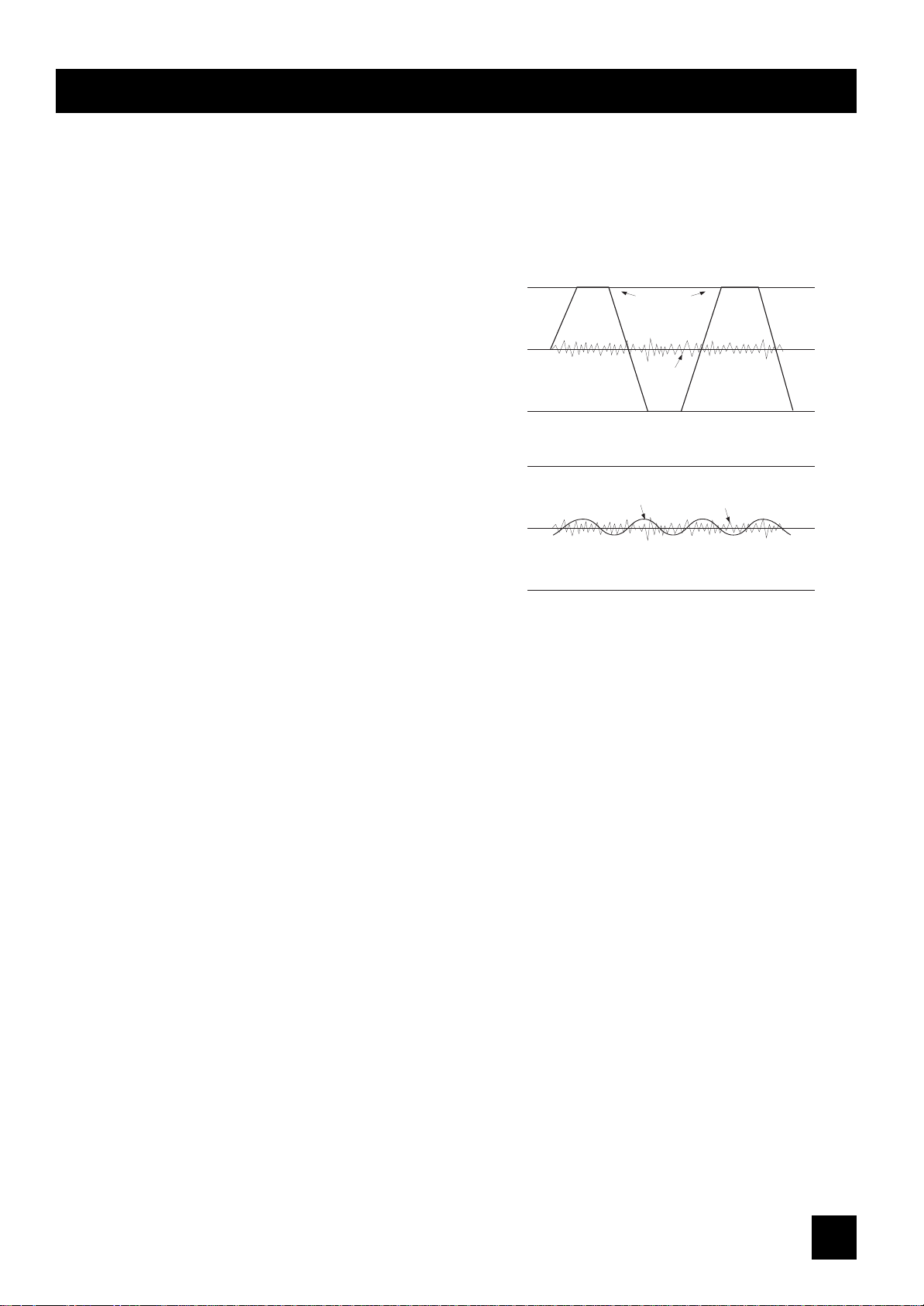
Gesamtpegel des Mischpults zu niedrig.- Sehen Sie sich dazu auch die veranschaulichenden Grafiken an.
Stellen Sie die einzelnen Mono-Eingang folgendermaßen ein:
o Gewünschte Signalquellen anschließen (üblicherweise die
Mikrofone an die MIC-Eingänge und alles andere an die
LINE-Eingänge). Stecken Sie erst Mikrone mit Phantom-
Speisespannung in die MIC-Buchsen und schalten erst dann
die Phantomspeisespannung ein.
o Drehen Sie die Master- und Gruppen-Fader ganz herunter.
o Drücken Sie den PFL-Taster, um das PFL-Signal auf den
Monitorweg und die Aussteuerungsanzeige zu legen.
o Stellen Sie einen typischen Signalpegel bei der jeweiligen
Signalquelle ein und halten den den PFL-Taster am Fader
gedrückt. Der Pegel des Signals wird nun auf der
Aussteuerungsanzeige sichtbar. Stellen Sie die
Vorverstärkung (GAIN) so ein, daß auf der
Aussteuerungsanzeige die gelbfarbende LED (0 dB) bei
ständig anliegendem Signal als ein maximaler Signalpegel
anliegt. Falls eine Signalquelle viele Obertöne besitzt (wie
z.B. Drums), ist eine weitaus höhere Aussteuerung von
+6/+9 erforderlich, um einen mittleren gleichmäßigen
Pegel zu erhalten.Hierbei bleibt genügend Verstärkungsreserve (Headroom), um Signalspitzen ohne Verzerrungen zu
verarbeiten.
o Wie zuvor beschrieben, stellen Sie die weiteren Eingangskanäle ebenso ein.
o Falls Sie feststellen sollten, daß Sie keine brauchbaren Pegel mit dem GAIN-Regler eingestellt bekommen, während Sie
den MIC-Eingang benutzen, versuchen Sie es mit dem LINE-Eingang.
Die Stereo-Eingänge können in gleicher Weise behandelt werden. Für professionelles Audio-Equipment mit einem +4 dB
Ausgangssignal drehen Sie das Gain-Poti ganz nach links. Eine höhere Eingangsverstärkung wird hingegen für
semiprofessionelle Geräte mit einem Ausgangspegel von -10 dB gewählt.
Sie haben nun Anfangseinstellungen für jede Eingangsquelle vorgenommen und können jetzt anfangen einen Mix
aufzubauen.
o Schließen Sie Ihren Verstärker (mit Lautsprechern) an die MIX- oder MONITOR-Ausgänge an, stellen die Verstärkung
des Verstärkers auf ungefähr 70% ein.Ziehen Sie die Master Fader langsam hoch und achten Sie auf Anzeichen von
Feedback oder Übersteuerung. Wenn Sie meinen, die Eingangsverstärkung müsse herabgestzt werden, nehmen Sie
sie langsam zurück.
o Hören Sie genauestens zu, um eventuelle rückkopplungsartige Sounds ausfindig zu machen. Falls Sie keine
befriedigende Eingangspegel-Einstellung erreichen, versuchen Sie andere Mikrofon- und Lautsprecher-Aufstellungen.
Ein korrekte Mikrofon-Aufstellung und die richtige Wahl eines passenden Mikrofons sind die wichtigsten Voraussetzungen
für einen erfolgreichen PA-Einsatz. Hierbei muß das Mikrofon so nah wie möglich an die Aufnahmequelle gebracht
werden, damit unerwünschte Umgebungsgeräusche vermieden werden. Dadurch kann am Mixer die Eingangsverstärkung
(GAIN) niedriger eingestellt werden und Feedback wird nicht auftauchen. Des weiteren werden Sie feststellen, daß ein gut
aufgestelltes Mikrofon kaum bemerkenswert entzerrt werden muß.
Bei zu geringem Pegel wird das Signal durch
Hintergrundrauschen verdeckt.
Signal
Rauschen
Bei zu hohen Signalpegel können Verzerrungen durch
Clipping auftreten.
abgeschittene
Amplitudenspitze
(Clipping)
Rauschen

1188
Die in den Eingangskanälen vom Folio Lite innewohnende, geringe Rauschentwicklung erlaubt auch ein anderes
Verfahren für die Anfangs-Einstellungen, bei der der gesamte Regelbereich der Eingangsfader ausgenutzt werden kann.
o Drehen Sie den Masterfader ganz nach rechts
o Bewegen Sie alle Eingangsfader auf die 0-Markierung
o Verstärken Sie mit dem TRIM-Poti solange das jeweilige Eingangssignal, bis das gewünschte Mischverhältnis stimmt.
EINSTELLUNGEN FÜRS RECORDING
Für den PA-Einsatz sind die Einstellungen sowie die Verkabelung am FOLIO LITE noch recht problemlos, doch beim
Recording (Aufnahme) werden viel größere Anforderungen an die Mixerausstattung gestellt, da hierbei nicht nur
Eingangssignale abgemischt werden müssen, sondern auch Monitor-Abmischungen für die Musiker aufgebaut werden,
um schon aufgenommene Spuren beim Overdubbing abhören zu können.
Eine typische Einstellung für eine Mehrspur-Aufnahme, die gleichermaßen für eine 2-Spur-Aufnahme gilt:
Schließen Sie die Eingangsquellen an den Mixer an und stellen die Vorverstärkung (GAIN) wie schon erwähnt ein. Die
MIX L/R Ausgänge verbinden Sie mit den Bandmaschinen-Eingängen.
Sie führen das jeweilige Kanal-Signal zu dem gewünschten Bandmaschinen-Eingang, indem Sie den PAN-Regler
entweder nach links oder rechts stellen. Drehen Sie etwa den PAN-Regler entgegen den Uhrzeigesinn ganz nach links, so
wird das Signal nur zum Group Output 1 oder Group Output 3 gelegt. Dadurch können Sie einzelne Kanalsignale zu
unterschiedlichsten Spuren schicken.
o Verbinden Sie nun die Bandmaschinen-Ausgänge mit den 2-TRK-Returns.
o An den AUX 1 schließen Sie einen Stereo-Verstärker (mit Lautsprechern) oder Kopfhörer an und stellen am Verstärker
einen normalen Pegel ein.
o Stellen Sie den 2-TRK-Pegel ganz nach links (-10 dB) oder entsprechend der Signalquellen höher ein.
o Drücken Sie den AUX 1 Pre-Schalter, um alle AUX1-Signale der kanäle Pre-Fade zu schalten.
o Stellen Sie mit den AUX-Send-Reglern der Eingangskanäle die Monitor-Mischung ein. (Stellen Sie dabei sicher, daß
jeweils alle anderen AUX-1-Send-Regler ganz zugedreht sind).
o Wird ein Kompressor verwendet, dann schließen Sie ihn an die Mix-Insert-Punkte an.
o Schließen Sie die anderen Effektgeräte an AUX2 an, und führen deren Ausgangssignale in nicht verwendete
Eingangs-, oder Stereo-/ FX-Return-Kanäle zurück, damit die Effekt-Signale mit den Originalsignalen gemischt
werden können.
Sollte es nötig sein, beim Monitormix zusätzlich das OFF-Tape-Signal zu hören (z.B. beim Overdubbing), dann schließen
Sie die Ausgänge der Bandmaschine an unbelegte Stereo- oder Mono-Eingänge an, die AUX1 addressieren können.
Es ist wichtig, die Ein- und Ausgangspegel von Ihrem Mischpult richtig einzustellen, damit Verzerrungen vermieden
werden und bestmöglich Aufnahmeresultate erzielt werden können.
o Stellen Sie den besten Pegel für Ihr Aufnahmegerät ein, indem Sie den Mix-Ausgängen ein entsprechendes Signal
entnehmen. Mit dem Monitor-Source-Schalter können Sie das Signal kontrollieren, daß zum Recorder geht.
o Machen Sie das Signal hörbar, indem Sie 2TRK mit dem Monitor-Source-Schalter anwählen. Heben Sie den Pegel an,
während Sie zwischen MIX und MONITOR SOURCE laufend und solange hin- und herschalten, bis kein
Pegelunterschied mehr hörbar, oder auf den LED-Ketten sichtbar ist.
 Loading...