


|
|
|
|
|
|
|
|
|
|
|
|
|
|
|
|
|
|
|
|
|
|
|
|
|
|
|
|
|
|
|
|
|
|
|
|
|
|
|
|
Introduction |
|
|
|
1 |
|||||
Safety Precautions |
|
|
|
1 |
|||||
Connections to Folio 4 |
|
|
|
2 |
|||||
The Controls at a glance - |
Mono Input Channel |
3 |
|||||||
|
|
|
|
|
|
Stereo Input Channel |
5 |
||
|
|
|
|
|
|
Groups, Returns & Aux Masters |
7 |
||
|
|
|
|
|
|
Master Section |
9 |
||
Initial Setting Up |
|
|
|
11 |
|||||
Setting Up for Multitrack Recording |
12 |
||||||||
The Controls in More Detail |
|
|
|
13 |
|||||
Applications - |
Stereo PA |
20 |
|||||||
|
|
|
|
|
|
Stereo PA with Centre Feed |
21 |
||
|
|
|
|
|
|
Stereo Recording |
22 |
||
|
|
|
|
|
|
4-Track Recording |
23 |
||
Glossary |
|
|
|
24 |
|||||
Technical Specifications |
|
|
|
25 |
|||||
System Block Diagram |
|
|
|
27 |
|||||
|
|
|
|
|
|
|
|
|
|
|
|
|
|
|
|
|
|
|
|
|
|
|
|
|
|
|
|
|
|

Introduction
Thank you for buying a SPIRIT FOLIO 4 mixer, brought to you with pride by the SPIRIT team of Peter, Graham, Malcolm, Martin, Peter, Brian, George, Colin, Tony, James, Mukesh, Andy, Candy and Simon. We hope you have as much fun as we did!
Owning a SPIRIT console brings you the expertise and support of one of the industry’s leading manufacturers and the results of over 20 years experience supporting some of the biggest names in the business.
Built to the highest standards using quality components, FOLIO 4 has evolved from the acclaimed FOLIO mixer with the addition of 4 Audio Subgroups, 8 Auxiliary Sends, Stereo Effects Returns, Dual VU/PPM Metering and comprehensive monitoring.
We have designed FOLIO 4 to be an instinctive and simple console to operate, but a few minutes spent reading this manual will help you to become familiar with the product away from the pressure of a live session, and allow you to gain full benefit from the superb performance which it offers.
Above all, remember that your SPIRIT mixer is designed to extend your creativity. The more that you explore the controls and the effect they have on the sound output, the more you will appreciate how you can influence and enhance the final sound.
SAFETY PRECAUTIONS
For your own safety and to avoid invalidation of the warranty please read this section carefully.
The FOLIO 4 desk must only be connected through the Power Supply Unit supplied.
The wires in the mains lead are coloured in accordance with the following code:
Green and Yellow: |
Earth |
Blue: Neutral
Brown: Live
As the colours of the wires in the mains lead may not correspond with the coloured markings identifying the terminals in your plug, proceed as follows:
∙The wire which is coloured Green and Yellow must be connected to the terminal in the plug which is marked with the letter E or by the earth symbol.
∙The wire which is coloured Blue must be connected to the terminal in the plug which is marked with the letter N or coloured Black.
∙The wire which is coloured Brown must be connected to the terminal in the plug which is marked with the letter L or coloured Red.
Ensure that these colour codings are followed carefully in the event of the plug being changed.
To avoid the risk of fire replace the mains fuse only with the correct value fuse, as indicated on the label on the power transformer unit.
1 |
SPIRIT FOLIO 4 |
|
|
|
|

These sockets accept 3-pole `A' gauge (TRS) jacks. Use these inputs for sources such as keyboards, drum machines, synths, tape machines or as returns from processing units. The inputs are BALANCED for low noise and immunity from interference, but you can use UNBALANCED sources by wiring up the jacks as shown, although you should then keep cable lengths as short as possible to minimise interference pick-up.
These jacks are an ideal place to connect the playback
of a tape machine or the output of an effects unit, without using up any of the LINE inputs. The input is unbalanced.
Connects to the Folio 4
Power Supply.
These independent unbalanced outputs are post Mix Insert, pre-fader, and are ideal for recording concerts to -10dBV tape inputs.
The mic input socket at the rear of the mixer accepts XLR-type connectors and is designed to suit a wide range of BALANCED or UNBALANCED low-level signals. Professional dynamic, condenser or ribbon mics are best because these will be LOW IMPEDANCE and therefore offer best noise immunity. Each mic input has a switch to turn on +48V PHANTOM POWER providing a suitable powering voltage for professional condenser mics. DO NOT use unbalanced sources with the phantom power switched on. The voltage on pin s 2 & 3 of the XLR connector may cause serious damage. Unplug any mics if you want to use the corresponding LINE Input to avoid the load presented by the mic from affecting the Line Input gain.
LINE INPUT Accepts 3-pole `A' gauge (TRS) jacks. Use this input for sources other than mics, such as keyboards, drum machines, synths, tape machines or guitars. The input is BALANCED for low noise and immunity from interference, but you can use UNBALANCED sources by wiring up the jacks as shown below, although you should then keep cable lengths as short as possible to minimise interference pick-up on the cable. Unplug anything in the MIC input if you want to use this socket.
These are pairs of unbalanced inputs suitable for tape playback or outputs from reverb units or other effects. The inputs are suitable for signals at -10dBV level (gain clockwise) to +4dBu.
SPIRIT FOLIO 4 |
2 |
|
|
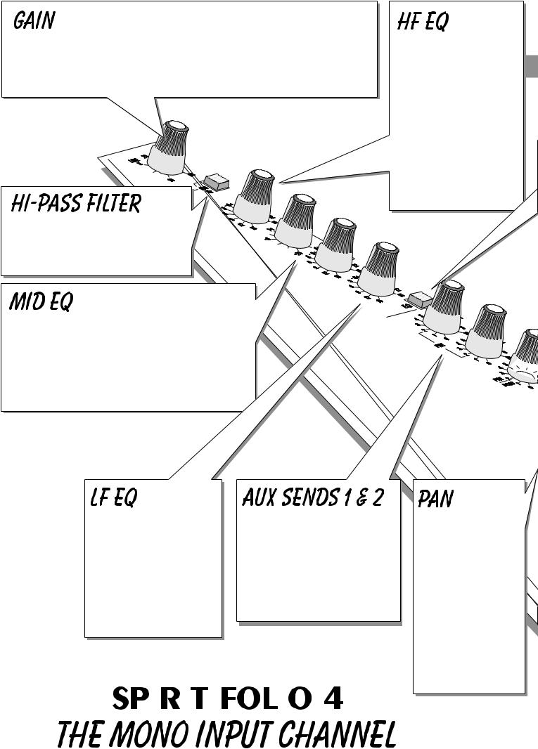
This knob sets how much of the source signal is sent to the rest of the mixer. Too high, and the signal will distort as it overloads the channel (shown by illumination of the PEAK LED), and causes clipping. Too low, and the level of any background hiss will be more noticeable and you may not be able to get enough signal level to the output of the mixer. Setting the knob to the `U' mark gives unity gain for the LINE input.
Pressing this switch reduces the level of bass frequencies only, and is a real bonus on a compact mixer.
Use this in live PA situations to reduce stage rumble or `popping' from microphones.
There are two knobs which work together to form a SWEPT MID EQ. The lower knob provides 15dB of boost and cut, just like the HF EQ knob, but the frequency at which this occurs can be set by the upper knob over a range of 250Hz to 6kHz. This allows some truly creative improvement of the signal in live situations, because this mid band covers the range of most vocals. Set the lower knob to the centre-detented position when not required.
Turn to the right to boost low (bass) frequencies by up to 15dB, adding warmth to vocals or extra punch to synths, guitars and drums. Turn to the left to cut low frequencies by up to 15dB for reducing hum, stage rumble or to improve a mushy sound. Set the knob to the centre-detented position when not required.
These sends are always PRE-FADE, PRE EQ and are unaffected by the ON switch. They would typically be used for Foldback or Monitor feeds, for which it is important that the send should be independent of the fader so that, for instance, the mix to artists headphones or monitor wedge is not affected by changes in fader level.
Turn to the right to boost high (treble) frequencies by up to 15dB, adding crispness to cymbals, vocals and electronic instruments. Turn to the left to cut these frequencies by up to 15dB, reducing hiss or over-emphasis of high-frequency consonants, which can
types of knob in position
is required
This control sets the amount of the channel signal feeding the Right and Left MIX or GROUP outputs, allowing you to move the source smoothly across the stereo image. Rotation fully anticlockwise feeds the signal solely to the Left mix bus, Group 1 or Group 3, while rotation clockwise sweeps the image to the right bus, Group 2 or Group 4.
|
|
|
|
|
|
|
|
|
e Forsee furtherpage13detail |
|
|
|
|
|
|
|
|
|
|
3 |
|||||||||
|
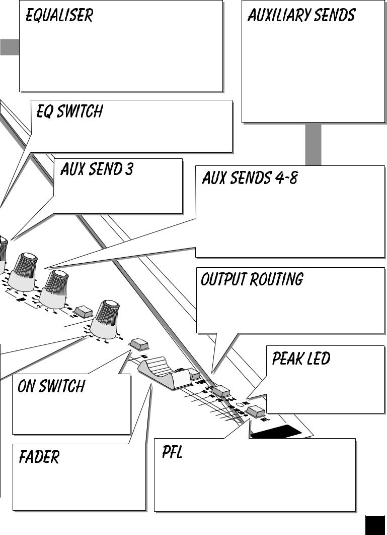
The Equaliser (EQ) allows precise manipulation of the sound, particularly to improve the sound in live PA applications where the original signal is often far from ideal. There are three sections, HF, MID and LF giving the sort of control usually only found on much larger mixers. The EQ knobs can have a dramatic effect, so use them sparingly and listen carefully as you change any settings so that you get to know how they affect the sound.
The EQ switch bypasses the Equalisation section when released and places it into the channel path when pressed. It would typically be used for simple comparison of the equalised and unequalised signal.
These controls route the input channel signal to any one or more of eight Auxiliary busses, which combine the sends from each channel, mixing them to separate outputs on the rear of the mixer. Since they are independent of the main outputs they can provide additional sources for foldback, effects processors or extra loudspeaker `fills'. Leave the knobs turned fully anticlockwise when not in use.
The ON switch turns on all post-fade outputs from the channel when pressed. Note that the Insert point is unaffected by the ON switch.
The linear FADER gives you smooth control of the overall signal level in the channel strip, allowing precise balancing of the various source signals being mixed to the Master Section.
always POST-FADE and would normally be used to processing units which are fed back into the mixer must fade out with the input channel. Aux 4 is an
individual mono send, while the 5/6 STE knob feeds the channel signal via the PAN control (see below) as a stereo pair to either Aux output s 5 & 6 or, with the 7-8 switch pressed, to Aux outputs 7 & 8.
The input channel signal is always routed to MIX or GROUPS as selected by the two ROUTING switches. The upper switch selects MIX when released or GROUPS when pressed, while the lower switch chooses between Groups 1-2 when released or Groups 3-4 when pressed.
This LED indicator warns when an excessively high signal level is present in the channel and will illuminate approximately 4dB before clipping
When the latching PFL switch is pressed, the pre-fade signal is fed to the headphones or monitor outputs, replacing the selected source (either Mix or Tape Return). The signal is also displayed on the right PPM meter. This is a useful way of listening to any one or more signals without interrupting the main mix, for adjusting signal quality or to set the input GAIN.
4
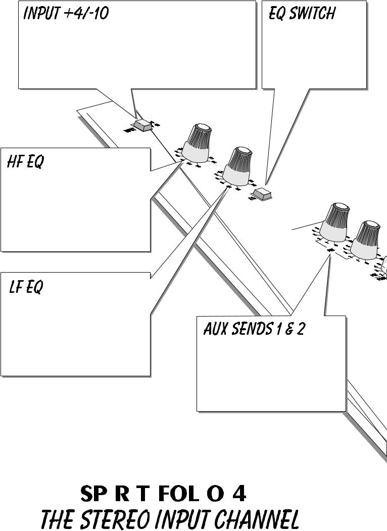
Most professional equipment uses input and output levels of +4dBu, but semi-professional tape machines or hi-fi systems use a lower level of -10dBV. This switch allows you to match the sources connected to the Stereo input jacks to either standard, which is important to ensure the best possible sound quality. If you are not sure what input level is appropriate, start with the switch UP to select +4dBu. If you are unable to achieve an adequate signal level, press the switch in for -10dBV.
HF EQ Turn to the right to boost high (treble) frequencies, adding crispness to percussion from drum machines, synths and electronic instruments. Turn to the left to cut these frequencies, reducing hiss or excessive brilliance. Set the knob in the centre-detented position when not required. The control has a shelving response giving 15dB of boost or cut at a fixed frequency.
The EQ switch disables the equaliser when released and activates it when pressed. It would typically be used for simple comparison of the equalised and unequalised signals.
LF EQ Turn to the right to boost low (bass) frequencies, adding extra punch to synths, guitars and drums. Turn to the left to reduce hum, boominess or improve a mushy sound. Set the knob to the centre-detented position when not required. The control has a shelving response giving 15dB of boost or cut at a fixed frequency.
These sends are always PRE-FADE, POST EQ and are not affected by the position of the ON switch. They would typically be used for Foldback or Monitor feeds, for which it is important that the send should be independent of the fader so that, for instance, the mix to artists headphones is not affected by changes in fader level.
|
|
|
|
|
|
|
|
|
e Forsee furtherpage16detail |
|
|
|
|
|
|
|
|
|
|
5 |
|||||||||
|
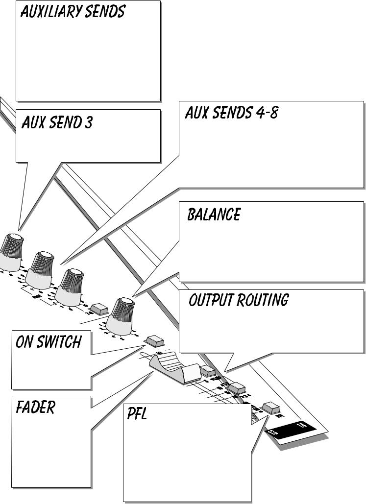
These controls route the input channel signal to any one or more of eight Auxiliary busses, which combine the sends from each channel, mixing them to separate outputs on the rear of the mixer. Since they are independent of the main outputs they can provide additional sources for foldback, effects processors or extra loudspeaker `fills'. Leave the knobs turned down when not in use.
|
These are always POST-FADE and would normally be used to |
|
This send can be set pre or post-fade as required |
drive effects processing units which are fed back into the mixer |
|
and which must fade out with the input channel. Aux 4 is an |
||
by the AUX 3 PRE switch on the Master Section. |
||
individual mono send, while the 5/6 STE knob feeds the |
||
|
||
|
channel signal via the BAL control (see below) as a stereo pair |
|
|
to either Aux output s 5 & 6 or, with the 7-8 switch pressed, to |
|
|
Aux outputs 7 & 8. This is particularly useful to feed the |
|
|
growing number of stereo effects units now available. |
This control sets the amount of the channel signal feeding the Right and Left MIX outputs, allowing you to balance the source in the stereo image. When the control is turned fully right or left you feed only that side of the signal to the mix. Unity gain is provided by the control in the centre-detented position.
The input channel signal is always routed to MIX or GROUPS as selected by the two ROUTING switches. The upper switch selects MIX when released or GROUPS when pressed, while the lower switch chooses between Groups 1-2 when released
or Groups 3-4 when pressed.
The ON switch turns on all post-fade outputs from the channel when pressed.
The linear FADER gives |
PFL When the latching PFL switch is |
|
you smooth control of the |
|
|
pressed, a pre-fade mono sum of the |
|
|
overall signal level in the |
|
|
channel signals is fed to the headphones or |
|
|
channel strip, allowing |
|
|
monitor outputs, replacing the selected |
|
|
precise balancing of the |
|
|
source (either Mix or Tape Return) and is |
|
|
various source signals |
|
|
also shown on the right PPM meter. This is |
|
|
being mixed to the |
|
|
a useful way of listening to any one or |
|
|
Master Section. |
|
|
more signals without interrupting the main |
|
|
|
|
|
|
mix, for adjusting signal quality or to check |
|
|
the input level. |
|
|
6 |
|
|
|
|
|
|
|
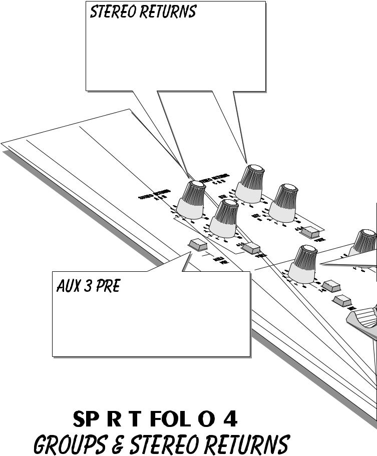
Two Stereo Return sections each comprise a pair of unbalanced inputs suitable for -10dBV or +4dBu sources. A mono signal may be plugged into the Left socket only for each pair to be fed equally to left and right busses. Each section is provided with a routing switch to select between a pair of Groups (switch released) or MIX (switch pressed). Stereo Return s A & B feed Groups 1 and 2, while Returns C & D feed Groups 3-4.
AUX 3 PRE The input channels provide both Preand Post-Fade AUX 3 sends which may be selected desk-wide on the Master Section. Press the AUX 3 PRE switch to make all of the AUX 3 Sends on the channel strips PRE-FADE. This means that they will all be unaffected by the position of the channel faders, making them ideal for FOLDBACK or MONITORING.
|
|
|
|
|
|
|
|
|
e Forsee furtherpage18detail |
|
|
|
|
|
|
|
|
|
|
7 |
|||||||||
|
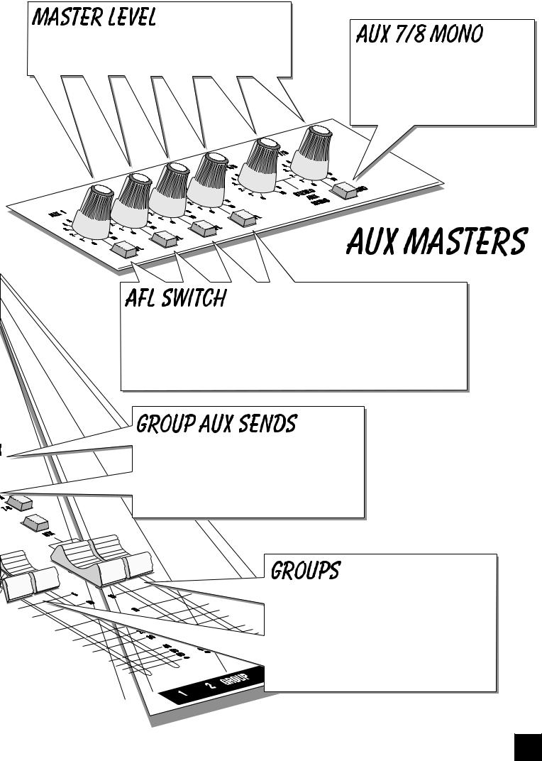
MASTER LEVEL Each of the Auxiliary Send busses is provided with a rotary master level control. Aux 1-4 are individual controls, while Aux 5/6 and Aux 7/8 are stereo pairs.
A MONO switch is provided to turn Aux 7/8 into summed mono outputs if a greater number of mono sends is required. Note that in this instance the position of the channel PAN and BAL controls may affect the Aux 7/8 output level.
Just like the PFL switches on the channels, you can monitor the AUX 1-4 outputs by pressing the AFL (After Fade Listen) switch, routing the AUX output signal to the MONITOR or PHONES.
The RIGHT PPM METER also switches from the selected source to display the PFL/AFL signal and the PFL/AFL LED lights to warn that a PFL or AFL switch is pressed. When you let go of the switch the Monitor returns to the previous source.
Each pair of Groups may feed post-fade to two Aux busses as a stereo pair, with a choice of Aux 5/6 or 7/8 depending on the position of the 7-8 switch. These controls will be found particularly useful for sending to reverb units, chained reverb effects, side fill feeds, alternate PA stacks or individual zones in clubs.
Two pairs of audio GROUPS may be fed from the Channels or Stereo Returns to form subgroups or separate controllable outputs..
MIX routes the Groups as a stereo pair to Mix Left/Right (Grou p 1 & 3 to Mix Left, Groups 2 & 4 to Mix Right).

 The FADERS control overall GROUP level to the chosen destination.
8
 Loading...