


 Loading...
|
|
|
|
|
|
|
|
|
|
|
|
|
|
|
|
GHOST Contents |
1 |
||

Manual written by Dominick¨ J. Fontana
© Harman International Industries Ltd. 1999 All rights reserved
Parts of the design of this product may be protected by worldwide patents.
Part No. ZM0168
Issue 5
Soundcraft is a trading division of Harman International Industries Ltd.
Information in this manual is subject to change without notice and does not represent a commitment on the part of the vendor. Soundcraft shall not be liable for loss or damage whatsoever arising from the use of information or any error contained in this manual.
No part of this manual may be reproduced, stored in a retrieval system, or transmitted, in any form or by any means, electronic, electrical, mechanical, optical, chemical, including photocopying and recording, for any purpose without the express written permission of Soundcraft.
It is recommended that all maintenance and service on the product should be carried out by Soundcraft or its authorised agents. Soundcraft cannot accept any liability whatsoever for any loss or damage caused by service, maintenance or repair by unauthorised personnel.
Harman International Industries Limited.
Cranborne House,
Cranborne Road,
Cranborne Industrial Estate,
Potters Bar,
Herts.,
EN6 3JN
UK.
Tel: 01707 665000
Fax: 01707 660482
2 |
GHOST Contents |

GHOST
Contents
1 |
Introduction |
1.1 |
|
|
|
Features of Ghost and Ghost LE |
1.3 |
2 |
Installation |
2.1 |
|
|
|
Optional Meterbridge |
2.3 |
|
|
User Modifications to Ghost |
2.4 |
|
|
Connections |
2.7 |
|
|
Din Connectors |
2.8 |
|
|
Hookup Diagrams |
2.9 |
|
|
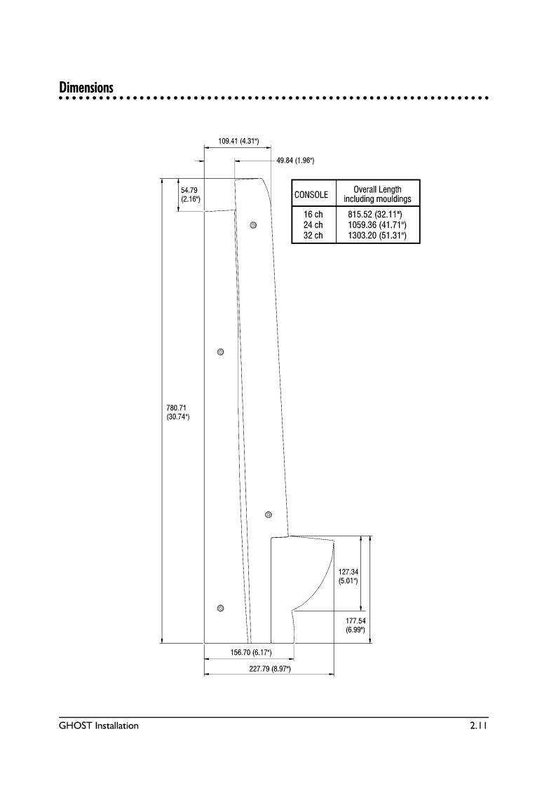
Dimensions |
2.11 |
3 |
Quick Start Guide |
3.1 |
|
|
|
Control Room Monitoring |
3.6 |
|
|
Studio Monitoring |
3.7 |
|
|
Adding Effects and Processors |
3.9 |
4 |
Block Diagram |
4.12 |
|
|
|
Block Diagram Explanation |
4.3 |
|
|
Signal Flow |
4.6 |
|
|
Overview of Main Signal Paths |
4.12 |
5 |
Back and Rear Panel Description |
5.1 |
|
|
|
Back Panel |
5.2 |
6 |
Functional Description |
6.1 |
|
|
|
The Mono Input Module |
6.2 |
|
|
Output and Master section |
6.15 |
7 |
Tutorial |
7.1 |
|
|
|
Multitrack Tutorial |
7.2 |
|
|
Studio Monitoring |
7.8 |
GHOST Contents |
i |

8 Application Notes |
8.1 |
|
|
Overview |
8.2 |
9 CPU Application Guide |
9.1 |
|
|
(NOT APPLICABLE TO GHOST LE) |
|
10 Troubleshooting |
10.1 |
|
|
General |
10.2 |
|
Troubleshooting Chart |
10.3 |
11 Specifications |
11.1 |
|
12 Glossary |
12.1 |
|
Appendix A |
A.1 |
|
|
Notes for Machine Control |
A.2 |
Appendix B |
B.1 |
|
|
MIDI Controller Numbers |
B.2 |
Appendix C |
C.1 |
|
|
MIDI Note Numbers to Mutes Conversion Chart |
C.2 |
|
MIDI Note Numbers to Expander Mutes Conversion Chart |
C.3 |
|
MIDI Note Numbers by Octave |
C.4 |
Appendix D |
D.1 |
|
|
MIDI Implementation Chart |
D.2 |
Appendix E |
E.1 |
|
|
Upgrading the Software |
E.2 |
ii |
GHOST Contents |

GHOST
1Introduction
GHOST Introduction |
1.1 |

Introduction
Thank you for purchasing the Soundcraft Ghost Music Production console. It has been designed to give you many years of trouble-free service. Please read this entire guide before using the console and then retain it for future reference. The terms console, mixer, and board are used interchangeably throughout this guide.
This guide covers two versions of the Ghost console, namely Ghost (with a CPU section containing a Timecode reader/generator, MIDI Machine Control, MIDI Mute Automation, and MIDI Controller Faders) and Ghost LE (with no CPU section). Both Ghost and Ghost LE are identical, except that Ghost LE does not have a CPU section above the Group faders. The top panel views in this guide sometimes show Ghost and sometimes Ghost LE. Except for the sections dealing with the CPU, which applies to Ghost only, everything else in this guide applies to both Ghost and Ghost LE.
This guide is composed of a Table of Contents, 12 chapters, 5 appendices, and an index. Following is an overview of the guide:
Chapter |
Title |
Description |
- |
Table of Contents |
Allows you to find broad topics easily. |
1 |
Introduction |
What you are currently reading. |
|
|
Contains basic information about Ghost. |
2 |
Installation |
Contains information about installing |
|
|
Ghost and modifying some of its default |
|
|
settings. Also has detailed hookup and |
|
|
connections diagrams. |
3 |
Quick Start |
Allows you to quickly get up and running |
|
|
Guide with Ghost. |
4 |
Block Diagram |
Contains a standard pictorial block diagram, |
|
|
as well as a plain English signal flow explana |
|
|
tion of that diagram. |
5 |
Back and Rear |
Contains a detailed description of all of |
|
|
Panel Description Ghost’s back and rear |
|
|
panel jacks. |
6 |
Functional |
Contains a detailed description of all of |
|
Description |
Ghost’s controls. |
7 |
Tutorial |
Explains in detail how to use Ghost for |
|
|
tracking, overdubbing, monitoring, adding |
|
|
effects and processors, punching in/out, |
|
|
bouncing tracks, and mixing down. |
8 |
Application |
Explains some of Ghost’s more advanced |
|
Notes |
uses. |
9 |
CPU Application |
Explains how to use the CPU section of |
|
Guide |
Ghost. (Not Applicable to Ghost LE.) |
1.2 |
GHOST Introduction |

10 |
Troubleshooting |
Contains some common problems, causes, |
|
|
and solutions. |
11 |
Specifications |
Lists complete specifications of Ghost. |
12 |
Glossary |
Contains some common audio terms and |
|
|
their definitions. |
- |
Appendices |
Contain information on MIDI Machine |
|
A through E: |
Control, Controller Numbers, Note |
|
|
Numbers, MIDI Implementation Chart, and |
|
|
upgrading Ghost’s software. |
- |
Index |
Contains a detailed index, which allows |
|
|
you to find a specific topic. |
It is suggested that you read this entire manual. If you’re the type that doesn’t like to read manuals, then we suggest the following:
For Advanced Users: Read the Introduction (up to "The Basics of In-Line Consoles"), Installation, Block Diagram, Back and Rear Panel Description, and Functional Description chapters, and the Appendices.
For Intermediate Users: Read the Introduction (up to "The Basics of In-Line Consoles"), Installation, Quick Start Guide, Block Diagram, Back and Rear Panel Description, Functional Description, and Application Notes chapters, and the Appendices.
For Beginning Users: You should read the entire manual, but at the very least you should read the entire Introduction, Installation, Block Diagram, Back and Rear Panel Description, Functional Description, Tutorial, Application Notes chapters, and the Appendices. Refer to the Troubleshooting and Glossary chapters, as needed.
For All Users: If you have the Ghost console with the CPU (not Ghost LE), then you should also read the CPU Application Guide chapter.
GHOST Introduction |
1.3 |

Features of Ghost and Ghost LE
Ghost is a professional 8-bus mixing console, primarily designed for multitrack recording and music production applications. It is an In-Line console, having a main input path and a secondary Mix B input path on each channel. This doubles the number of inputs at mixdown, yet the console remains compact. Following are some of Ghost’s features:
lSoundcraft’s ProMic ultra-low-noise mic preamp, with +60dBu input sensitivity, is included on every channel.
lEvery channel features a mic input, a line input, individually switched phatom power, mic/line switch, phase reverse, and 100Hz Low-Cut Filter.
lMulti-busing on every channel allows Direct Outs on each channel to also be used as Group Outs, allowing you to send a signal from any channel to any of 32 tape tracks (24 tape tracks with 24 channel Ghost).
lPowerful 4-band "British" EQ, featuring high/low shelving EQ and two fullyparametric mid EQs, with continuously variable Q (bandwidth) control and EQ In/Out switch.
l6 mono (4 usable at once per channel) and 2 stereo auxiliary sends. Sends 1/2 are switchable as a pair between pre-fader and post-fader. Sends 3/4 can be routed as a pair to Sends 5/6.
l100mm faders and inserts for channels, groups, and main L/R mix.
lVariable brightness Signal Present LED for each channel.
lPeak LED for each channel.
lAutomated/Manual Mutes (Cut) for each channel. (Mutes cannot be automated on Ghost LE.)
lSolo (either PFL or Solo-in-Place) for each channel.
lMix B section on each channel features a line input, source select (tape or channel), rotary fader, pan, PFL Solo, and automated/manual Mutes (Cut). (Mutes cannot be automated on Ghost LE.)
lTape Input Trim pot for the Mix B line input.
lHigh/Low shelving EQ and Auxs 3/4 (5/6) may be switched into the Mix B path.
lReverse switch allows you to route the channel input to the Mix B path and the Mix B input to the channel path.
l8 Group buses with AFL solo and routing to the L/R bus.
l4 stereo effects returns, each with PFL Solo and routing to the L/R bus or any of the group buses.
l2 separate Studio Foldback monitoring sections with AFL Solo.
lControl Room monitoring section with headphone jack, mono check, provisions for two stereo line inputs (DAT deck, two-track deck, CD player, etc.), and two sets of control room monitors.
lA 2-frequency oscillator.
lTalkback section with built-in mic.
l8 Aux Send Master pots with AFL Solo.
1.4 |
GHOST Introduction |

lMix B Master pot with provision for routing Mix B to the L/R bus.
lPFL/AFL Trim pot with Solo LED and Solo-in-place switch with LED.
l12-segment vertical peak LED meters for the 8 Groups and for the Control Room/Solo outputs.
lBy using the channel inputs, Mix B inputs, and 4 stereo FX returns at mixdown, you have a total of 56 inputs from the 24 channel Ghost and a total of 72 inputs from the 32 channel Ghost.
lOptional 24 channel expander module is available.
lOptional meterbridge is available.
Additional features of Ghost (Not Found on Ghost LE)
lMIDI In/Out/Thru jacks.
lSMPTE timecode In/Out jacks and Sony 9-pin connector.
lSMPTE/MTC timecode reader/generator/converter.
lMIDI Machine Control transport control buttons with jog/shuttle wheel for controlling external tape machines, video machines, hard disk recorders, and MIDI sequencers.
l4 mute groups.
l128 snapshots for MIDI muting, which may be recalled manually, from timecode, or from MIDI Program Change Messages.
lDynamic Mute Automation (with an external MIDI sequencer).
l4 MIDI Controller Faders for controlling external MIDI effects and other MIDI parameters by transmitting MIDI Control Change data.
Frame Sizes & Expander Module
Ghost is available in two frames sizes:
l24 Input Channels
l32 Input Channels
There is also an optional 24 channel expander module available, which allows you to expand Ghost to 48 channels or 56 channels. With the 4 stereo FX returns, this will give you either 104 or 120 inputs at mixdown.
Meterbridge
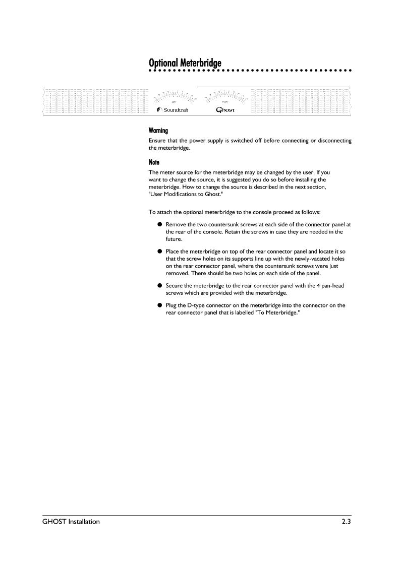
There is an optional meterbridge for each console size and for the expander module. The meterbridge contains a vertical 12 segment peak LED meter for each channel, which can be internally configured to show either the Mix B (tape) inputs or the channel inputs. It also includes two
20-segment LED VU meters for the Control Room/Solo outputs.
Power Supply
Use only the power supply that comes with the console and make sure it is configured for the country you will be using it in.
GHOST Introduction |
1.5 |

Contact Information
You may write, phone, fax, or EMAIL Soundcraft at the following places:
In Europe: |
|
Soundcraft |
Telephone: +44 (0) 1707 665000 |
Harman International Industries LTD. |
FAX: +44 (0) 1707 660742 |
Cranborne House, Cranborne Rd., |
EMAIL: info@soundcraft.co.uk |
Potters Bar, Herts, EN6 3JN, UK. |
|
In the United States: |
|
Soundcraft USA |
Telephone: 1(615) 360-0471 |
1449 Donelson Pike |
FAX: 1(615) 360-0273 |
Nashville, Tennessee 37217 |
|
The Basics of In-Line Consoles
When using a console for traditional multitrack recording, it is necessary to be able to record the console’s channel inputs to tape, while at the same time monitoring previously recorded tape tracks. When you’re finished recording, you must be able to play the finished multitrack master tape through the console, make adjustments to the tape tracks, and then record your mix to your 2-track mixdown deck. This means that the outputs of the mixer (group outs or direct outs) have to be connected to the inputs of the multitrack deck for recording purposes, while at the same time the outputs of the multitrack deck have to be connected to the inputs of the mixer (tape returns) for monitoring and mixdown purposes. However, the requirements for simply monitoring tape tracks while overdubbing are different than what is needed when mixing down those tracks.
Before in-line consoles, split console designs were used. Since this is not a primer on split consoles, just the basics will be given here. With split consoles the channel strips and the tape returns were split, with the channels on the left side and the tape returns located above the group masters on the right side of the board. While tracking and overdubbing, the channel outputs were routed to the multitrack inputs and the multitrack outputs were routed to the tape returns. The channels were used for recording and the tape returns were simply used to monitor previously recorded tape tracks. This meant that if you wanted to monitor 32 tape tracks, you had to have 32 separate tape returns located apart from the channel strips. And those returns might have only provided level and pan controls for each track. Since the tape returns didn’t offer all the features of the channel strip (such as EQ and Aux Sends), and didn’t provide a way to route the tape tracks to the mixdown deck, when it came time for mixdown, the multitrack outputs had to be repatched from the tape returns to the channel strip inputs. This allowed you to use all of the features of the channel strip and to route the tape tracks to the
2-track deck during mixdown. While this is an oversimplification of the process, it is sufficient to illustrate the point.
The drawbacks of a split console design are as follows: the console usually has to be very wide to accommodate all the tape returns; as the number of tape returns increases on a console, so do the number of channel strips, so if you need 32 tape returns, you might have to buy a console with 64 or more channel strips; you have to repatch when you want to mixdown and then repatch again when you want to track and overdub; while mixing down, the tape returns are unused; and split console designs cost more than an equivalent in-line design.
An in-line console solves these problems, while remaining compact and affordable. With today’s digital multitrack recorders, hard disk recorders, and MIDI sequencers, many studios have 24 or more tracks (whether tape, disk, or sequenced) that need to be monitored, yet not as many channel inputs are needed for recording purposes. With an in-line console, the tape return controls are physically located right in the channel strip, or "in-line" with the channel strip, hence,
1.6 |
GHOST Introduction |
the name. You have as many tape returns as you have channel strips, yet no extra width is added to the console regardless of the number of returns, although there is a slight increase in the depth of the console.
As mentioned, Ghost is an in-line console. There are 2 separate inputs for each channel strip. The main channel input is called "Channel" and the tape return input is called "Mix B." Note that you can connect any line level source to Mix B; it does- n’t have to be the output of a tape deck. Normally, whatever is connected to the mic or line input on the rear panel is routed to the channel strip and you use the channel strip’s controls to process that input. And whatever is connected to the Mix B/Tape Ret jack on the rear panel is routed to the Mix B section, located within the same channel strip, and you use Mix B’s controls to process the Mix B input separately from the channel input.
Generally speaking, while recording basic tracks and overdubbing, you connect the sources you want to record to the channel inputs and you connect the sources you want to monitor to the Mix B inputs. You’ll usually want to monitor previously recorded tape tracks, hard disk tracks, and MIDI sequenced tracks. At mixdown, you’ll press the Reverse switch on each channel, which will route the Mix B inputs to the channel strip and the channel inputs to Mix B. You’ll also be able to route all of the Mix B outputs as a group to the L/R bus for mixdown to a 2-track recorder. This is how you double the number of inputs at mixdown. By doing this, all of your tape tracks are now routed to the channel strips, with the full complement of channel strip controls available to the tape tracks for mixdown, while at the same time allowing you to connect sources, such as MIDI tracks, that don’t need as much processing, to the Mix B inputs, which can also be recorded to the 2-track deck. This means that Mix B, which is normally used as a tape return, can also be used for recording during mixdown. In addition, Mix B has access to some of the channel EQ and Aux Sends.
Complete descriptions of all the features, a Quick Start Guide, and a Tutorial follow later in this guide.
GHOST Introduction |
1.7 |

1.8 |
GHOST Introduction |


GHOST
3Quick Start Guide
GHOST Quick Start Guide |
3.1 |

Quick Start Guide
We suggest that you read this entire manual before using Ghost; but for those who want to get started right away, we have provided this QUICK START GUIDE. This will get you up and running quickly. The basic procedures given here are taken from the TUTORIAL chapter, which contains much more detailed information. If you don’t understand something in this chapter, then refer to the TUTORIAL. However, to get the full benefit of Ghost’s many features, it is suggested that at some point you read this entire manual.
Recording Basic Tracks (Tracking)
Procedure:
1.Reset Console. "Zero Out" or reset the console. That means to set all controls to their off or neutral positions.
2.Connections. Connect your input sources to the channel MIC and LINE inputs.
3.Select Inputs. Use the MIC/LINE switch to select the appropriate input for each channel. Press the 48V switch for condenser mics, where required. Make sure the REV switch is not depressed.
4.Recording methods. There are 3 methods you can use to send the channel signal to a multitrack tape recorder (MT), and they are outlined below:
a.Using the Group Output jacks. Use this method if the GRP 1-8 output jacks are connected to the inputs of your multitrack recorder. The group number should match the tape input number. In the channel strip, press the assign switch for the tape track(s) you want to record on. Next, use the pan pot to send the signal to the Group output jack for the track(s) you wish to record on. Pan left for odd-numbered tracks; right for even-num- bered tracks; and centre for both tracks. Then, turn up the channel fader to its nominal position, as indicated by the fader marking 3/4 of the way up. Finally, turn up the appropriate Group fader(s) to its nominal position.
b.Using the DIR/TAPE SND jack as a Group Output. Use this method if the DIR/TAPE SND jacks are connected to the inputs of your multitrack recorder, and you wish to use the Groups for recording. The channel number should match the tape input number.
First, press the DIR/GRP n switch (on the rear connector panel) on the channel that represents the tape track you wish to record on. Then note the GRP n number on the switch. For instance, both channels 2 and 10 will have a switch that reads DIR/GRP 2. This means that the channel 2 and channel 10 DIR/TAPE SND jacks will act as Group 2 output jacks, when their DIR/GRP 2 switches are pressed.
Next assign all the inputs you’re recording to the appropriate Group number(s) and use the pan pot to send the signal to the appropriate Group bus. Pan left for odd-numbered groups; right for even-numbered groups; and centre for both groups.
Then, turn up the channel fader to its nominal position, as indicated by the fader marking 3/4 of the way up. Finally, turn up the Group fader(s) to its nominal position.
c.Using the DIR/TAPE SND jack as a Direct Output: Use this method if the DIR/TAPE SND jacks are connected to the inputs of your multitrack recorder, and you wish to record directly from the channel outputs. The channel number should match the tape input number.
3.2 |
GHOST Quick Start Guide |

This method differs from method (b), above, because you’re using the DIR/TAPE SND jack as a Direct Output from the channel and the Group buses are not involved at all. The channel signal, post-fader and post-mute, will be routed to this jack for direct recording to your multitrack.
To use this method, first make sure the DIR/GRP n switch (on the rear connector panel) is in the DIR (UP) position for all channels that you wish to record. Then, turn up the channel fader to its nominal position, as indicated by the fader marking 3/4 of the way up. The pan pot and assign switches will have no effect on the Direct Output signal.
Select one of the above three recording methods and then proceed to step 5.
5.Setting Up The MT. On the MT, insert a tape, wind to where you wish to begin recording, set the counter to zero, put the appropriate tracks into RECORD-READY mode, and set the recording level controls of the MT, if any, to their nominal positions.
6.Monitoring. To learn how to listen to the sound you are recording, see the section below entitled, "Control Room Monitoring." To learn how to send the sound you are recording to the musicians in the studio, see the section below entitled, "Studio Monitoring."
With the musicians playing, set up preliminary monitor mixes for the Control Room and Studio.
7.Gain Structure. If you have the optional meterbridge and it’s set for channel input monitoring, then gradually turn up the Input Sensitivity knob until the meterbridge channel input meter indicates 0.
In all other instances, press the channel SOLO switch. Make sure the SIP switch in the master section is off. This will display the channel signal on the CRM/SOLO-L/R meters in the master section. Gradually turn up the Input Sensitivity knob until the meters indicate 0, then turn the SOLO switch off.
In either case, the Signal Present LED should be brightly lit, and the PK LED should light only occasionally, if at all.
8)LCF & Phase. Use the Low-Cut Filter (LCF) switch to get rid of low frequency noise. The Phase switch should be in the up position, unless you know your input cables are wired incorrectly or if you’re employing M-S recording techniques.
9.EQ. If you want to add EQ to the channel inputs, first press the EQ IN switch and make sure the EQ MIX B button is up. Then apply the EQ as needed. The HF/LF shelving EQ can be boosted or cut 15dB. The HMF/LMF EQ are true parametrics and allow you to select the centre frequency, the bandwidth of that frequency (with the Q control), and apply boost or cut of 15dB.
10.Effects & Processing. If you want to add effects or processing, then see the section below, entitled, "Adding Effects and Processors."
11.Adjust Faders. Adjust the channel and group faders, as required, so that the multitrack’s meters display the desired recording level.
12.Recording. Set up your final monitor mixes, and then have the musicians stop playing. Put the MT into RECORD mode and have the musicians play the song. When the song is over, STOP the multitrack and rewind the tape to zero.
13.Playback. Play back the tracks you have just recorded. To let the musicians in the Studio hear the take, select CRM as the Source in the appropriate Studio Foldback section.
GHOST Quick Start Guide |
3.3 |

14.Record Another Take. If dissatisfied, record over the first take or add another take after it. Before recording again, remember to unselect CRM and select AUX 1-2 as the Studio Foldback Source, if necessary.
15.Proceed With Overdubbing. When you are satisfied with the take of the basic tracks, you can proceed to "Overdubbing," below.
Overdubbing
Procedure:
1.Tape Channels. On all channels that contain the outputs of previously recorded tape tracks, press the REV switch and set the MIX B SRCE switch to CHAN. This routes the Tape Returns to both the Channel and MIX B paths. These are your Tape channels and are for monitoring purposes only.
2.Connections. Connect your input sources for the overdub to the channel MIC and LINE inputs. Do not connect them to any Tape channels. These are your Input channels.
3.Select Inputs. On the Input channels, use the MIC/LINE switch to select the appropriate input for each channel. Press the 48V switch for condenser mics, where required. Make sure the REV switch is not depressed and set the MIX B SRCE switch to TAPE.
4.Select Recording Method. Select one of the 3 recording methods, from above, and follow the directions for signal routing and channel/group fader positioning for each Input channel.
5.Setting Up The MT. On the MT, rewind the tape to the beginning of the song, or to a point before the overdub will be recorded, set the counter to zero, and put the appropriate track(s) into RECORD-READY mode. Make sure that all previously recorded tracks are not in RECORD-READY mode. Then set the recording level controls of the MT, if any, to their nominal positions and start playing the tape.
6.Monitoring And Gain Structure. With the musicians playing along with the tape, set up Control Room and Studio preliminary monitor mixes of the overdub being recorded and of previously recorded tape tracks. (See Control Room/Studio Monitoring, below.) Then use the INPUT SENSITIVITY knob to set your input gain structure for the overdub, using the optional meterbridge or the CRM/SOLO-L/R meters, and the SIG and PK LEDs. (See "Recording Basic Tracks," above.)
7.LCF & Phase. Use the LCF and PHASE switches, as required. (See above.)
8.EQ. Apply EQ, as required. (See above.)
9.Effects & Processing. If you want to add effects or processing, then see the section below, entitled, "Adding Effects and Processors."
10.Adjust Faders. Adjust the channel and group faders, as required, so that the multitrack’s meters display the desired recording level.
11.Recording. Set up your final monitor mixes, of both the live signal and of previously recorded tape tracks, and then have the musicians stop playing. Put the MT into RECORD mode and have the musicians play the overdub. When the overdub is over, STOP the multitrack and rewind the tape to zero or to a point right before the overdub.
12.Playback. Play back the overdub you have just recorded. To let the musicians in the Studio hear the take, select CRM as the Source in the appropriate Studio Foldback section.
3.4 |
GHOST Quick Start Guide |

13.Record Another Take. If dissatisfied, record over the first take of the overdub. Before recording again, remember to unselect CRM and select AUX 1-2 as the Studio Foldback Source, if necessary.
14.Proceed With Overdubs & Mixing Down. When you are satisfied with the take of the overdub, proceed to record the next overdub. When you’re satisfied with all the tracks on the tape, you can proceed to "Mixing Down", below.
Mixing Down
Procedure:
1.Inputs. "Zero Out" the console and then press the REV switches to route all your tape tracks to the channel path. Channel inputs on those channels will be routed to the MIX B path. If you have additional input sources, such as MIDI tracks, and extra channels available (that are not being used for tape tracks), then route the additional sources to the channel path. If you have more input sources than channels, then connect some to the channel inputs and some to the MIX B inputs. Then decide where best to route those extra sources, between the channel and MIX B paths. You can also use the Effects Returns as line level source inputs, but remember that you’ll probably also need inputs for the outputs of your effects devices. Make sure the MIX B SRCE switch is set to TAPE (UP) on all channels, unless you wish to use it as a pre-fader send for the channel path.
2.Assignment & Master Levels. Assign all channels and Effects Returns that are in use to the L/R MIX by pressing the L/R assign switch on the channels and the MIX assign switch on the Effects Returns. Press the MIX B TO MIX switch in Ghost’s MIX B master section and set the MIX B rotary master fader about 75% up. Set the MIX L/R master fader to the top of its travel.
3.Using Groups. If you’re grouping some sources, assign them to the appropriate Group buses and then assign the Group buses to the L/R MIX, using the TO MIX- L, R, and L+R switches in the Group master section. Turn the appropriate Group faders about 75% up.
4.Monitoring. Set the CRM SRCE to monitor MIX A only, turn up the level control, and make sure MONO CHECK is off. To send the mix to the studio, select CRM as the source in the appropriate Studio Foldback section and turn up its level control.
5.Input Gain. Adjust the INPUT SENSITIVITY and TAPE TRIM knobs, if needed. (See above.)
6.Setting Up The MT. Rewind the MT tape, set the counter to zero, and start playback. If the MT has an output level control, set it to its nominal position. If you’re syncing a sequencer to the tape, make sure it’s set up properly, so that the MIDI tracks are also playing.
7.Practice The Mix. As the tape plays, set the relative levels of the tape/MIDI tracks using the channel and MIX B faders, (and the FX level controls, if they are being used as inputs). Use the PAN and BAL controls to set the stereo perspective. USE EQ, effects, and processors, as needed. (See "Effects and Processors," below.) Use the MUTE Automation system, as needed. (Not Ghost LE). (See the "CPU Application Guide" in this manual.) Use the MONO CHECK switch periodically to check for mono compatibility. Listen to the mix through your main speakers, your alternate speakers, if any, and headphones. Keep practicing the mix, until you’re happy with it, then rewind the MT tape to the beginning of the song.
GHOST Quick Start Guide |
3.5 |

8.Setting Up The 2-Track. Insert a new tape in your 2-track recorder and rewind it to the beginning. Roll about one minute into the tape and use the TO TAPE switches in the Talkback and Oscillator sections to record any announcements and tones that are needed. Allow the tape to roll a bit past the tones, stop the 2-track, and set the counter to zero. Then, set the deck to RECORD-READY mode and set its input level control to its nominal position.
9.Setting Levels. Play the MT tape again, and adjust the MIX L/R Master fader, MIX B Master fader, and Group Master faders, to retain the proper balance of your mix, while at the same time, achieving the proper level on your 2-track recorder’s meters. The proper recording level should be achieved with the 2-track’s input control at its nominal position. Then rewind the MT tape to the beginning of the song.
10.Recording The Mix. To commit your final mix to tape, start the 2-track in RECORD mode and then start playback of the MT tape. Make any mix moves that are necessary and when the song is completed, stop the 2- track, then stop the MT. Press the appropriate 2-TK switch in the CRM SRCE section, unselect MIX A, and then rewind and play back the 2-track tape. If you’re not satisfied with the final mix, then unselect the 2-TK CRM SRCE switch, select MIX A, and try the mix again. If you are satisfied with the mix, then make a dub of the 2-track master and play the dub on as many systems as you can. If you’re not satisfied, then mix it again. If the mix meets with your approval on these other systems, then make a backup copy of the 2-track master and label everything. This final 2-track stereo master tape is now ready for mastering and/or duplication.
3.6 |
GHOST Quick Start Guide |
Loading...