


User Guide v1.4
 ®
®
®
Vi3000 USER MANUAL |
IMPORTANT INFORMATION |
IMPORTANT
Please read this manual carefully before using your mixer for the first time.
This equipment complies with the EMC directive 2004/108/EC and LVD 2006/95/EC
This product is approved to safety standards IEC 60065:2001 (Seventh Edition) +A2:2010
EN60065:2002 +A1:2006 +A2:2010 +A11:2008 +A12:2011 UL60065 2012 7th Edition
CAN/CSA-E60065-03 + A2: 2012 And EMC standards EN55103-1: 2009
EN55103-2: 2009
Warning: Any modification or changes made to this device, unless explicitly approved by Harman, will invalidate the authorisation of this device. Operation of an unauthorised device is prohibited under Section 302 of the Communications act of 1934, as amended, and Subpart 1 of Part 2 of Chapter 47 of the Code of Federal Regulations.
NOTE: This equipment has been tested and found to comply with the limits for a Class B digital device, pursuant to Part 15 of the FCC Rules. These limits are designed to provide reasonable protection against harmful interference in a residential installation. This equipment generates, uses and can radiate radio frequency energy and, if not installed and used in accordance with the instructions, may cause harmful interference to radio communications. However, there is no guarantee that interference will not occur in a particular installation. If this equipment does cause harmful interference to radio or television reception, which can be determined by turning the equipment off and on, the user is encouraged to try to correct the interference by one or more of the following measures:
*Reorient or relocate the receiving antenna
*Increase the separation between the equipment and the receiver
* Connect the equipment into an outlet on a circuit different from that to which the receiver is connected.
* Consult the dealer or an experienced radio/TV technician for help
© Harman International Industries Ltd. 2014 All rights reserved
Parts of the design of this product may be protected by worldwide patents. Part No. 5042292
Rev 1.0
E&OE September 2014
Soundcraft is a trading division of Harman International Industries Ltd. Information in this manual is subject to change without notice and does not represent a commitment on the part of the vendor. Soundcraft shall not be liable for any loss or damage whatsoever arising from the use of information or any error contained in this manual. No part of this manual may be reproduced, stored in a retrieval system, or transmitted, in any form or by any means, electronic, electrical, mechanical, optical, chemical, including photocopying and recording, for any purpose without the express written permission of Soundcraft.
Harman International Industries Limited
Cranborne House, Cranborne Road, Potters Bar, Hertfordshire, EN6 3JN, UK
Tel: +44 (0)1707 665000
Fax: +44 (0)1707 660742 http://www.soundcraft.com
IMPORTANT INFORMATION

®
Vi3000 USER MANUAL: CONTENTS
1.0 INTRODUCTION |
12.0: METERING |
1.1: Saftey Notices & Warnings |
12.1: Inputs |
1.2: Product Warranty |
12.2: Busses |
|
13.0: EDIT SYSTEM |
2.0: SPECIFICATIONS |
(COPY, PASTE, AND LIBRARY) |
2.1: Console block diagram |
13.1: Copy, Paste, Undo |
3.0: QUICK START GUIDE |
13.2: Library Basics |
13.3: Library File Screen |
|
4.0: HARDWARE OVERVIEW |
14.0: SNAPSHOTS, CUELISTS, GLOBAL FILTER |
4.1: Local I/O |
14.1: Console Controls |
4.2: MADI / DANTE Sources / Switching |
14.2: Cuelist Control |
5.0 OPERATIONS OVERVIEW |
14.3: Cue Details |
14.3.1: Cue Number & Timecode |
|
5.1: Manual Conventions |
14.3.2: Snapshot/Cue Name |
5.2: Vistonics II |
14.3.3: MIDI |
5.3: Console Bays |
14.3.4: GPIO |
5.4: FaderGlow™ |
14.4: Snapshot Filters |
5.5: Buttons |
14.4.1: Snapshot Filter Scope |
5.6: Encoders |
14.4.2: Global Filter |
5.7: Gangs |
15.0: TALKBACK & OSCILLATOR |
5.8: Labelling |
|
6.0: INPUTS |
15.1: Console Controls |
15.2: Oscillator Setup & Use |
|
6.1: Navigation - Fader Pages |
15.3: Talkback Setup |
6.2: The Channel Strip |
15.4: Talkback Return Setup |
6.3: Encoder Mode |
16.0: MAIN MENU |
6.4: VST Control |
|
6.5: Touchscreen / Signal Path |
16.1: Main (Screen, Security) |
6.5.1: Input Section |
16.2: Shows |
6.5.2: EQ |
16.2.1: Show File Data |
6.5.3: Dynamics |
16.3: GPIO |
6.5.4: Busses |
16.4: Sync |
6.5.5: Output Section |
16.5: Tielines |
7.0: OUTPUTS |
16.6: FX |
16.7: MIDI |
|
7.1: LCR Mix Masters |
16.8: Log |
7.2: Bus Configuration |
16.9: Settings |
7.3: Bus Master Control |
16.10: System |
7.3.1: Master Vistonics Control |
17.0: LEXICON FX |
7.3.2: Channel Strip |
|
7.3.3: Processing Chain |
17.1: Using The FX Processors |
7.3.4: Graphic EQs |
17.1.1: Tap Tempo Functionality |
8.0: MATRIX SYSTEM |
17.2: FX Algorithms & Parameters |
17.2.1: Reverbs |
|
9.0: MUTE & VCA GROUPS |
17.2.1: Delays |
17.2.1: Misc |
|
9.1: Mute Groups |
18.0: VM² WIreless Status Monitoring / HiQnet |
9.2: VCA Groups |
|
9.3: Aux VCA Groups |
18.1: HiQnet Network Configuration |
10.0: MONITORING |
18.1.1: VM ² Device List |
18.2: Status Displays |
|
10.1: Console Controls |
18.2.1: Channel Strip Status |
10.2: Setup |
18.2.2: VST Status |
10.2.1: MON Setup |
|
11.0: SOLO SYSTEM |
|
11.1: Primary Behaviour |
|
11.2: Input Priority Mode |
|
11.3: Autocancel Behaviour |
|
11.4: Follow Output Solo Mode |
|
CONTENTS
®
Vi3000 USER MANUAL |
1.0: Introduction |
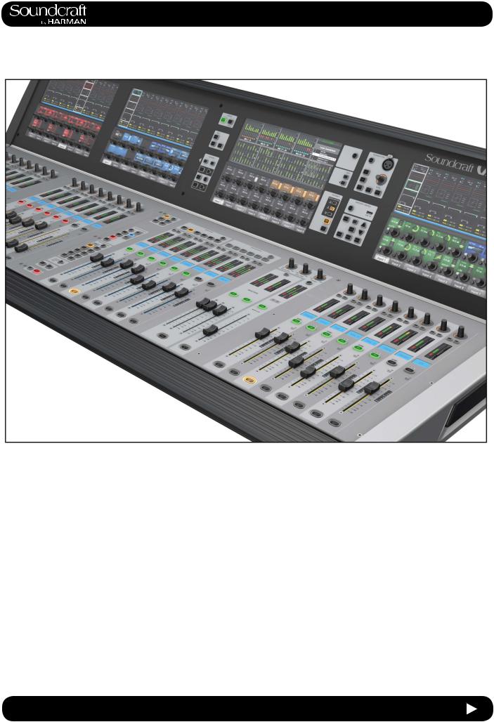
Welcome To The Vi3000!
New Look
The Soundcraft Vi3000 features an all-new appearance with a more efficiently designed control surface, 36 faders, 24 mono/stereo busses and a sweeping black screen panel with four Vistonics II™ touchscreen interfaces with sleek, updated 3D graphics. Because the Vi3000 has four touchscreens, it’s the only console in its class that can be used by two engineers at the same time. And at show time... Settings libraries, copy/paste functions, sophisticated automation and radio mic status monitoring, FaderGlow™, processing from dbx, BSS, Lexicon and Universal Audio (Optional Realtime Rack), and more will not let you down.
SpiderCore DSP
The Vi3000 is a console with friends in high places. Sound quality is assured by Soundcraft SpiderCore - a brand new 40-bit floating point DSP engine that mixes FPGA and DSP technology in a unique combination that maximises I/O routing and DSP mixing capability in a footprint small enough for inclusion within a control surface.
FX
Internal FX come courtesy of 4 independent stereo Lexicon multi effects units, each providing a choice of 14 reverbs, 7 delays and 8 pitch shifting effects, patchable to input channels, aux outputs and channel inserts. BSS third-octave Graphic EQ is available on every bus output, with fader bays illuminating in red to indicate GEQ mode.
...And More FX
The Vi3000 can also accommodate the new Soundcraft
Realtime Rack, a hardware/software unit designed in collaboration with plug-in manufacturer Universal Audio that provides access to 74 industry-standard UAD plug-ins.
DANTE As Standard
The Vi3000 is the first Soundcraft console to incorporate a Dante interface as standard, for seamless digital audio networking with Dante-enabled devices.
Connectivity
In addition to a full complement of analog and digital inputs and outputs, the console provides MIDI, USB, Ethernet, DVI out, Dante/MADI record feed outputs, redundant power supply and other connections. The Vi3000 has two expansion bays that can be fitted with MADI Stagebox cards, to connect multiple Soundcraft Stagebox input expander modules.
Shine A Light
Along with its greatly expanded functionality, the Vi3000 retains all the features that have made the Soundcraft Vi
Series the consoles of choice for live sound engineers worldwide, such as FaderGlow™ - illuminated faders that display different colors according to function, the ability to store and recall snapshots and cues, compatibility with Soundcraft’s ViSi app that allows remote control from an iPad.
Optional 64 channel stagebox
With up to 48 on-board mic inputs, Vi3000 is happy to work with existing analogue multicore systems. Also available is an optional remote stagebox housing 64 analogue mic/line inputs and 32 analogue line outputs, with 48V phantom power and a 80Hz HPF before the A-D converters. Mic amp gain can be controlled remotely from the console surface.
1.0 |
1.0 Introduction |
|
®
Vi3000 USER MANUAL |
1.1: INTRODUCTION > SAFETY |
SAFTEY NOTICES
For your own safety and to avoid invalidation of the warranty please read this section carefully.
THIS UNIT MUST BE EARTHED
Under no circumstances should the mains earth be disconnected from the mains lead.
The wires in the mains lead are coloured in accordance with the following code:
Earth: Green and Yellow (Green/Yellow - US)
Neutral: Blue (White - US)
Live: Brown (Black - US)
As the colours of the wires in the mains lead may not correspond with the coloured markings identifying the terminals in your plug, proceed as follows:
The wire which is coloured Green and Yellow must be connected to the terminal in the plug which is marked with the letter E or by the earth symbol.
The wire which is coloured Blue must be connected to the terminal in the plug which is marked with the letter N.
The wire which is coloured Brown must be connected to the terminal in the plug which is marked with the letter L.
Ensure that these colour codings are followed carefully in the event of the plug being changed.
The internal power supply unit contains no user serviceable parts. Refer all servicing to a qualified service engineer, through the appropriate Soundcraft dealer.
1.1 |
1.1: INTRODUCTION > SAFETY |

®
Vi3000 USER MANUAL |
1.1: INTRODUCTION > SAFETY |
WARNINGS
•Read these instructions.
•Keep these instructions.
•Heed all warnings.
•Follow all instructions.
•Clean the apparatus only with a dry cloth.
•Do not install near any heat sources such as radiators, heat resistors, stoves, or other apparatus (including amplifiers) that produce heat.
•Do not block any ventilation openings. Install in accordance with the manufacturer’s instructions.
•Do not use this apparatus near water.
•Do not defeat the safety purpose of the polarized or grounding type plug. A polarized plug has two blades with one wider than the other. A grounding type plug has two blades and a third grounding prong. The wide blade or the third prong are provided for your safety. When the provided plug does not fit into your outlet, consult an electrician for replacement of the obsolete outlet.
•Protect the power cord from being walked on or pinched particularly at plugs, convenience rececta - cles and the point where they exit from the apparatus.
•Only use attachments/accessories specified by the manufacturer.
•Unplug this apparatus during lightning storms or when unused for long periods of time.
•Refer all servicing to qualified service personnel. Servicing is required when the apparatus has been damaged in any way such as power-supply cord or plug is damaged, liquid has been
spilled or objects have fallen into the apparatus, the apparatus has been exposed to rain or moisture, does not operate normally or has been dropped.
•Use only with the cart, stand, tripod, bracket or table specified by the manufacturer, or sold
with the apparatus. When the cart is used, use caution when moving the cart/apparatus combination to avoid injury from tip-over.
•No naked flame sources, such as lighted candles or cigarettes etc., should be placed on the apparatus.
•Warning: To reduce the risk of fire or electric shock, do not expose this apparatus to rain or moisture. Do not expose the apparatus to dripping or splashing and do not place objects filled with liquids, such as vases, on the apparatus.
•No user serviceable parts. Refer all servicing to a qualified service engineer, through the appropri - ate Soundcraft dealer.
•Ventilation should not be impeded by covering the ventilation openings with items such as newspapers, table cloths, curtains etc.
•It is recommended that all maintenance and service on the product should be carried out by Sound - craft or its authorised agents. Soundcraft cannot accept any liability whatsoever for any loss or damage caused by service, maintenance or repair by unauthorised personnel.
1.1 |
1.1: INTRODUCTION > SAFETY |

®
Vi3000 USER MANUAL |
1.2: INTRODUCTION > WARRANTY |
WARRANTY
1 Soundcraft is a trading division of Harman International Industries Ltd.
End User means the person who first puts the equipment into regular operation.
Dealer means the person other than Soundcraft (if any) from whom the End User purchased the Equipment, pro - vided such a person is authorised for this purpose by Soundcraft or its accredited Distributor.
Equipment means the equipment supplied with this manual.
2 If within the period of twelve months from the date of delivery of the Equipment to the End User it shall prove defective by reason only of faulty materials and/or workmanship to such an extent that the effectiveness and/or usability thereof is materially affected the Equipment or the defective component should be returned to the Dealer or to Soundcraft and subject to the following conditions the Dealer or Soundcraft will repair or replace the defec - tive components. Any components replaced will become the property of Soundcraft.
3 Any Equipment or component returned will be at the risk of the End User whilst in transit (both to and from the Dealer or Soundcraft) and postage must be prepaid.
4 This warranty shall only be available if:
a)The Equipment has been properly installed in accordance with instructions contained in Soundcraft’s manual.
b)The End User has notified Soundcraft or the Dealer within 14 days of the defect appearing; and
c)No persons other than authorised representatives of Soundcraft or the Dealer have effected any replacement of parts maintenance adjustments or repairs to the Equipment; and
d)The End User has used the Equipment only for such purposes as Soundcraft recommends, with only such operating supplies as meet Soundcraft’s specifications and otherwise in all respects in accordance Soundcraft’s recommendations.
5 Defects arising as a result of the following are not covered by this Warranty: faulty or negligent handling, chem - ical or electro-chemical or electrical influences, accidental damage, Acts of God, neglect, deficiency in electrical power, airconditioning or humidity control.
6.The benefit of this Warranty may not be assigned by the End User.
7.End Users who are consumers should note their rights under this Warranty are in addition to and do not affect any other rights to which they may be entitled against the seller of the Equipment.
1.2 |
1.2: INTRODUCTION > WARRANTY |

® |
|
Vi3000 USER MANUAL |
2.0: Vi 3000 Specifications |
|
Vi3000 Specifications |
Frequency Response |
|
Stagebox or Local Mic input to Line output |
+0/-1dB, 20Hz-20kHz |
AES/EBU In to AES/EBU Out +0/-0.2dB, 20Hz-20kHz |
|
T.H.D. & Noise
(22Hz-22kHz, unweighted)
Stagebox or Local Mic In (min gain) to Local Line Out <0.004% @ 1kHz
Stagebox Mic In (max gain) to Local Line Out <0.035% @ 1kHz
Mic Input E.I.N. |
<-127dBu (150Ω source) |
(22Hz-22kHz bandwidth, unweighted) |
|
Residual Noise |
-95dBu |
(Stagebox line output; no inputs routed, Mix fader @0dB)
CMRR |
80dB @ 1kHz |
|
(Stagebox Mic input) |
|
|
Sampling Frequency |
48kHz |
|
Latency |
< 2ms @48kHz |
|
(Stagebox Mic Input to Local Line output)
AES/EBU Input Sample Rate 32–108kHz (with SRC enabled)
DSP Resolution 40-bit floating point
Internal Clock
Accuracy < +/- 50ppm
Jitter < +/- 2ns
2.0 |
2.0: Vi 3000 Specifications |

®
Vi3000 USER MANUAL |
2.0: Vi3000 Specifications |
External Sync BNC Wordclock, Dante network clock
Input & Output Levels
Mic/line Inputs |
+28dBu max |
Line Outputs |
+22dBu max |
Nominal Operating Level |
+4dBu (-18dBFS) |
Input & Output Impedances
Mic Inputs |
|
|
2k7Ω |
|
All other analogue Inputs |
>10kΩ |
|
||
Line Outputs |
|
|
<75Ω |
|
AES/EBU Outputs |
|
110Ω |
|
|
Oscillator |
20Hz to 20kHz/Pink/White Noise, variable level |
|||
Channel Filters |
|
|
|
|
Mic In HP Filter |
|
80Hz fixed, 12dB per octave |
||
Channel HP Filter |
20Hz-600Hz, 18dB per octave |
|||
Channel LP Filter |
1kHz-20kHz, 18dB per octave |
|||
EQ (Inputs and Bus Outputs) |
|
|||
HF |
20Hz-20kHz, +/-18dB, Q= 0.3-8.7 or shelving |
|||
Hi-Mid |
20Hz-20kHz, +/-18dB, Q=0.3-8.7 |
|||
Lo-Mid |
20Hz-20kHz, +/-18dB, Q=0.3-8.7 |
|||
LF |
20Hz-20kHz, +/-18dB, Q= 0.3-8.7 or shelving |
|||
Metering |
Internal 20-segment LED bargraphs plus 9-segment gain reduction meters for all inputs and |
|||
|
Outputs Peak hold variable from 0-2s. |
|||
Mains Voltage Operating Range |
90-264V, 47-63Hz, auto-ranging |
|||
2.0 |
2.0: Vi3000 Specifications |
®
Vi3000 USER MANUAL |
2.0: Vi3000 Specifications |
Mains Power Consumption
Console 300W (both PSUs operating)
Stagebox (64in/32out) 150W (both PSUs operating)
Internal Mass Storage |
120GB SSD Hard Drive |
Temperature/Humidity Range |
|
Operating Temperature Range |
0°C – 45°C (32°F – 113°F) |
Relative Humidity 0% – 90%, non-condensing Ta=40°C (104°F)
Storage Temperature Range |
-20°C – 60°C (-4°F – 140°F) |
Weight 54kg
Soundcraft reserves the right to improve or otherwise alter any information supplied in this document or any other documentation supplied hereafter. E&OE 05/2014
2.0 |
2.0: Vi3000 Specifications |
|
1.2
Diagram Block Vi3000 1:.2
INPUTS |
PATCH |
INPUT CHANNELS / MATRIX |
MASTER / MIX / MONITORING |
PATCH |
OUTPUTS |
MIC/LINE LOCAL I/O
a |
PAD |
A |
|
D |
|
|
|
|
|
|
16 |
Up to 3 cards with 16
Channels per card
|
AES USB TB HP |
|
|
|
d |
SFC |
D D |
|
|
d |
|
|||
SFC |
D D |
8 |
||
|
||||
a |
USB |
D D |
|
|
|
D D |
|
||
|
Dante or MADI (IN) |
|
||
d 64 |
D |
|
64 |
|
|
D |
|
|
|
|
|
|
|
|
|
|
|
|
|
|
|
|
|
|
MASTER |
MIX/MTX |
SOLO |
|
|
|
|
|
|
|
|
|
|
|
|
|
|
|
|
|
|
|
|
|
|
|
|
|
|
|
|
|
|
|
|
MASTER L MASTER R MASTER C |
MIX or MTX 1 MIX or MTX 2 |
MIX or MTX 24 |
SOLO L SOLO R |
|
|
|
|
|
|
|
|
|
|
|
|
|
|
|
|
|
|
|
|
|
|
|
|
|
|
|
|
|
|
|
|
|
|
MASTER LEFT |
|
|
|
|
|
|
|
|
|
|
|
|
LINE OUT LOCAL I/O |
|
||
|
|
|
|
|
|
|
PROCESSING |
|
|
|
|
|
|
|
|
|
|
|
|
|
|
|
GRM |
|
|
|
|
|
|
|
a |
|||
|
|
|
|
|
|
|
|
|
|
|
|
|
|
|
|
|
|
|
|
|
|
|
|
|
|
|
|
D |
A |
|
||||
|
|
|
|
|
|
|
|
|
|
|
|
|
|
|
|
|
|
I |
|
DYNAMIC |
I |
|
|
I |
|
LEVEL |
|
|
MASTER L |
|
|
|
||
|
|
|
|
|
|
|
|
|
|
|
|
|
|
|
|
|
|
EQUALIZER |
FADER |
ON |
LOW- |
DELAY |
16 |
|
|
|
|
|||||||
|
|
|
|
|
|
|
|
|
|
|
|
|
|
|
|
|
|
N |
4 band |
Limiter |
N |
N |
CUT |
|
|
|
|
|
|
|
||||
INP 1 |
|
|
|
|
|
|
|
|
|
|
|
|
|
|
MASTER L |
|
|
S |
Compressor |
S |
|
|
S |
|
|
|
|
|
|
Up to 3 cards with 16 |
|
|||
|
|
LOW |
|
|
|
|
|
|
|
|
|
|
|
|
|
|
|
|
|
|
|
|
|
|
|
|
||||||||
INP 2 |
S |
|
I |
|
|
|
DYNAMIC |
|
I |
|
|
I |
|
MASTER R |
|
|
|
|
|
|
|
|
|
|
|
|
|
to MTX |
|
|
Channels per card |
|
||
PHASE |
& |
GATE/Dees |
EQUALIZER |
DELAY |
FADER |
ON |
PAN |
|
|
|
|
ST |
|
|
|
|
|
|
|
|
|
|
|
|
|
|||||||||
|
E |
TRIM |
HI |
N |
4 band param |
Limiter |
N |
N |
|
|
|
SOLO |
|
LINK |
|
PF |
|
PF |
|
|
|
|
|
|
|
|
|
|
||||||
OSC |
L |
S |
|
|
Compressor |
|
S |
|
|
S |
|
|
|
|
|
|
|
|
|
TRIM INS SEND |
|
|
|
|
|
|
||||||||
|
CUT |
|
|
|
|
|
|
|
MASTER C |
|
|
|
|
|
|
AON |
|
AF |
|
|
|
|
|
|
|
|
||||||||
|
|
|
|
|
|
|
|
|
|
|
|
|
|
|
|
|
|
|
|
|
|
AON |
|
|
|
|
|
|
|
|
|
|
||
INS RET |
|
|
|
|
|
|
DYN |
|
LINK (ST) |
PF |
AF |
|
|
Follow/ |
|
|
|
MASTER RIGHT |
|
|
|
|
|
|
|
|
|
|
|
|
AES USB TB HP |
|
||
|
|
|
|
|
|
|
|
to CH Dyn |
|
|
|
|
Bundle |
|
|
|
|
|
|
|
|
|
|
|
|
|
|
|
|
|||||
|
|
|
|
|
|
|
|
|
|
|
|
|
|
|
|
|
|
|
|
|
GRM |
|
|
|
|
|
|
|
|
|||||
|
|
|
|
|
|
|
|
|
|
|
|
|
|
|
|
|
|
|
|
|
|
|
|
|
|
|
|
|
D |
|
|
d |
||
|
|
|
|
|
|
|
|
|
of same |
|
AF |
|
|
|
MIX 1 |
|
|
|
|
|
|
|
|
|
|
|
|
|
|
|
D |
|
||
|
|
|
|
|
|
|
|
|
Bay A/B |
|
PF |
|
|
|
|
|
I |
EQUALIZER |
DYNAMIC |
I |
|
|
I |
LOW- |
LEVEL |
|
|
MASTER R |
|
|
|
d |
||
KEY |
|
|
|
|
|
|
|
|
PE |
|
PP |
|
|
|
|
|
|
N |
Limiter |
N |
FADER |
ON |
N |
DELAY |
|
D |
|
|
||||||
|
|
|
|
|
|
|
|
|
PE |
|
|
|
|
|
|
4 band |
CUT |
|
|
8 |
D |
|
|
|||||||||||
|
|
|
|
|
|
|
|
|
|
|
|
|
|
|
|
|
|
S |
|
Compressor |
S |
|
|
S |
|
|
|
|
|
|
D |
|
USB |
|
|
|
|
|
|
|
GUI |
|
|
|
|
|
|
|
MIX 24 |
|
|
|
|
|
|
|
|
|
|
|
|
|
to MTX |
|
D |
a |
|||
|
|
|
|
|
|
GATE |
Dees |
|
|
|
|
|
|
|
|
|
|
|
|
|
|
|
|
|
|
|
|
|
|
D |
|
p |
||
|
|
|
|
|
|
|
|
|
|
|
|
|
|
|
|
SOLO |
|
|
|
PF |
|
PF |
|
|
TRIM |
|
|
|
A |
|
||||
|
|
|
|
|
|
|
|
|
AF |
|
|
|
|
|
|
|
|
|
|
|
AON |
|
AF |
|
|
|
INS SEND |
|
|
|
|
|
|
|
|
|
|
|
|
|
|
|
|
LEVEL |
PF |
|
|
|
|
|
|
|
|
|
|
|
|
|
AON |
|
|
|
|
|
|
|
|
|
|
|
|
|
|
|
|
|
|
GRM |
PP |
|
|
|
|
DIR OUT |
|
|
|
|
|
|
|
|
|
|
|
|
|
|
|
|
|
|
|
|
|
|
|
|
|
|
|
|
|
|
|
|
|
|
|
|
|
MASTER CENTRE |
|
|
|
|
|
|
|
|
|
|
|
|
|
|
|
||
|
|
|
|
|
|
|
|
|
PP |
|
|
|
|
|
|
|
|
|
|
|
|
|
|
GRM |
|
|
|
|
|
|
|
|
||
|
|
|
|
|
|
|
|
|
|
|
|
|
AFL |
|
|
|
|
|
|
|
|
|
|
|
|
|
|
|
|
|
|
|
||
|
|
|
|
|
|
|
|
|
|
|
|
|
|
SOLO L |
|
|
|
|
|
|
|
|
|
|
|
|
|
|
|
|
|
|
|
|
|
|
|
|
|
|
|
|
|
|
|
|
|
|
|
|
|
I |
|
DYNAMIC |
I |
|
|
I |
|
LEVEL |
|
|
MASTER C |
|
|
|
|
|
|
|
|
|
|
|
|
|
|
|
|
|
To MTX |
|
|
|
|
|
|
EQUALIZER |
|
|
LOW- |
|
|
|
|
|
|
|
||||||
|
|
|
|
|
|
|
|
|
|
|
|
|
|
SOLO R |
|
|
N |
Limiter |
N |
FADER |
ON |
N |
DELAY |
|
|
|
|
|
||||||
|
|
|
|
|
|
|
|
|
|
|
|
|
|
|
|
|
4 band |
CUT |
|
|
|
Dante and MADI (OUT) |
|
|||||||||||
|
|
MONO INPUT |
SC/ES |
|
|
|
|
|
|
|
|
|
|
|
S |
|
Compressor |
S |
|
|
S |
|
|
|
|
|
|
|
||||||
|
|
|
|
|
|
|
|
|
PFL |
|
|
|
|
|
|
|
|
|
|
|
|
|
|
|
64 |
|
|
D |
64 d |
|||||
|
|
SOLO |
|
|
|
|
|
|
|
|
P SOLO |
|
|
|
|
|
|
|
|
|
|
|
|
|
to MTX |
|
|
|
D |
|
||||
|
|
CHANNEL 1 to 96 |
|
|
|
|
|
|
|
TRIM |
|
|
|
SOLO |
|
|
|
PF |
|
PF |
|
|
TRIM INS SEND |
|
|
|
|
|
|
|||||
|
|
|
|
|
|
|
|
|
INS SEND |
|
|
|
|
|
|
AON |
|
AF |
|
|
|
|
|
|
|
|
||||||||
|
|
|
|
|
|
|
|
|
|
|
|
|
|
|
|
|
AON |
|
|
|
|
|
|
|
|
|
|
|||||||
D21m compatible expansion slot
x 64 |
|
64 |
|
X |
X D |
|
D21m compatible expansion |
|
|
|||
|
|
slot |
|
# |
||
x 64 |
|
|
|
|
64 |
|
|
X |
|
X D |
|
|
|
|
|
|
||||
|
|
|
|
|
|
|
FX
LEX 1
LEX 2
LEX 3
LEX 4
CLOCK
Dante
 WCLK
WCLK
48k
MIDI
IN
OUT
|
|
|
|
|
|
|
|
|
|
|
|
|
|
|
DIR OUT |
96 |
MIX BUS 1 |
|
|
|
MASTER L |
|
|
|
|
|
|
|
|
|
|
|
|
BUS FEED 1 |
|
|
MASTER R |
|
|
|
|
|
|
|
|
|
|
INS SEND |
24 |
|
|
|
|
|
|
|
|
|
|
|
|
|
|
||||
|
|
|
MASTER C |
|
|
|
|
|
|
|
|
|
|
|
|
|
|
|
|
|
|
MIX or MTX 1 |
|
|
|
|
|
|
GRM |
|
|
|
|
|
|
|
|
|
|
|
|
|
|
|
|
|
|
|
|
|
MIX BUS 24 |
|
|
|
MASTER L |
I |
EQUALIZER |
DYNAMIC |
I |
|
|
I |
LOW- |
LEVEL |
|
|
MIX BUS 1 |
BUS FEED 24 |
|
|
MASTER R |
N |
Limiter |
N |
FADER |
ON |
N |
DELAY |
||||||
|
|
|
4 band |
CUT |
|
|
||||||||||
|
|
|
MASTER C |
S |
Compressor |
S |
|
|
S |
|
|
|
|
|||
|
|
|
|
|
|
|
ST |
|
|
|
|
|
|
|
|
to MTX |
|
|
|
|
|
SOLO |
|
LINK |
|
PF |
|
PF |
|
|
TRIM |
|
|
|
|
|
|
|
|
|
|
|
|
|
|
|
|
|||
|
|
|
MTX 1 |
|
|
|
|
|
AON |
|
AF |
|
|
|
INS SEND |
|
|
|
|
ON |
|
|
|
|
|
AON |
|
|
|
|
|||
|
|
SEL |
|
|
|
|
|
|
|
|
|
|
|
|
|
|
MTX 1_SRC |
24 |
|
|
|
|
|
|
|
|
|
|
|
|
|
|
|
MTX |
|
|
|
|
|
|
|
|
|
|
|
|
|
|
||
|
|
1 |
MTX 24 |
ON |
|
|
|
|
|
|
|
|
|
|
|
|
|
|
|
|
|
|
|
|
|
|
|
|
|
|
|
|
|
|
|
|
MTX 1 |
|
MIX or MTX 24 |
|
|
|
|
|
|
GRM |
|
|
|
|
|
|
|
ON |
|
|
|
|
|
|
|
|
|
|
|
||
|
|
SEL |
|
I |
|
DYNAMIC |
I |
|
|
I |
|
|
|
|
|
|
MTX 16_SRC |
24 |
|
|
EQUALIZER |
|
|
LOW- |
LEVEL |
|
|
MIX BUS 24 |
|||||
MTX |
|
|
N |
Limiter |
N |
FADER |
ON |
N |
DELAY |
|||||||
|
MATRIX |
24 |
MTX 24 |
|
S |
4 band |
Compressor |
S |
|
|
S |
CUT |
|
|
|
|
|
ON |
|
|
|
|
|
|
|
to MTX |
|||||||
|
|
|
|
|
|
|
|
|
|
|
|
|
|
|||
|
|
|
|
|
SOLO |
|
|
|
PF |
|
PF |
|
|
TRIM INS SEND |
|
|
|
|
|
|
|
|
|
|
|
AON |
|
AF |
|
|
|
||
|
|
|
|
|
|
|
|
|
|
AON |
|
|
|
|
|
|
OSC |
|
OSC |
|
|
|
|
|
|
|
|
|
|
|
|
|
|
TB_SRC |
|
|
TB to BUS / MTX / EXT |
|
|
|
|
|
|
|
|
|
|
|
|
|
TB SEND |
OSC to TB |
|
|
|
|
|
|
|
|
|
|
|
|
|
|
|
|
|
|
|
|
|
|
|
|
|
|
|
|
|
|
||
|
|
SEL |
TB |
|
|
|
|
|
|
|
|
|
|
|
|
|
|
|
TB_MIC |
|
TB |
|
|
|
|
|
|
|
TB EXT |
|
|
|
|
|
|
TB to EXT |
|
|
|
|
|
|
|
|
|
|
|
|
|
|
|
|
|
|
||
|
|
|
|
|
|
|
|
|
|
|
|
|
|
|
|
Source pre BLEND |
A or B |
|
|
|
|
|
|
|
|
|
|
|
|
|
|
|
|
|
|
|
|
|
|
|
|
|
|
|
|
|
|
|
|
|
|
|
|
SOLO pre TRIM |
ENAB A/B |
|
|
|
|
|
|
|
|
|
|
|
|
|
|
|
|
|
|
|
|
|
|
|
|
|
|
|
|
|
|
SOLO TRIM |
|
|
|
|
|
|
|
|
|
|
|
|
|
|
|
|
BLEND |
IN |
BUS 1 |
BUS 24 |
|
|
MON Delay |
MON FADER |
|
|
|
|
|
|
|
|
|
[-inf..- 10 dB] |
|
|
|
|
[+/- 10 dB] |
|
|
0..2000 mS |
ON |
|
|
|
|
|
|
|
|
|
|
|
|
|
|
IN/OUT |
|
|
Logic |
|
MNTR B |
|
|
|
|
|
|
|
|
|
|
|
|
|
|
|
|
|
|
|
||
|
|
|
MONITOR_A |
|
|
|
|
|
|
SOLO |
|
|
|
|
|
|
|
|
|
|
|
|
|
|
|
|
|
Enable |
|
|
|
|
|
|
|
||
|
|
|
|
|
|
|
|
|
|
|
|
|
|
|
|
|
|
|
|
|
|
|
|
|
Left |
+ |
|
|
|
+ |
|
LR/ |
Delay |
TB |
+ |
|
MON_A LEFT |
|
|
|
|
|
|
|
|
|
|
|
DIM |
|
|
|||||
|
|
|
|
|
|
|
|
|
|
|
|
|
|
|
|
|
||
|
|
|
|
MON_A_Source |
SEL |
Right |
|
|
|
|
|
|
RR/ |
|
TB |
|
|
MON_A RIGHT |
MON_A_Source |
|
|
3 |
+ |
|
|
|
|
+ |
LL |
|
+ |
ON |
|||||
3 |
|
|
|
A |
|
|
|
|
|
|
Delay |
DIM |
|
|||||
MON_B_Source |
3 |
|
|
|
|
Center |
|
|
|
|
|
|
|
Delay |
|
|
|
MON_A CENTER |
|
|
|
|
|
|
|
|
|
|
|
|
|
|
|
|
|||
MON_HP_Source |
3 |
|
|
|
|
|
|
|
|
|
|
|
|
|
|
|
|
|
|
|
|
|
|
|
|
|
|
|
|
|
|
|
|
|
|
||
TB RET |
|
|
|
|
|
|
|
|
|
|
IN/OUT |
|
|
|
|
|
|
|
TB from ext |
|
|
|
|
|
|
|
|
|
|
|
|
|
|
|
|
|
|
|
|
MONITOR_B |
|
|
|
|
|
|
SOLO |
|
|
|
|
|
|
|
||
|
|
|
|
|
|
|
|
|
|
|
|
|
|
|
|
|||
|
|
|
|
|
|
|
|
|
|
|
Enable |
|
|
|
|
|
|
|
|
|
|
|
|
|
Left |
+ |
|
|
|
+ |
|
LR/ |
Delay |
TB |
+ |
|
MON_B LEFT |
|
|
|
3 |
MON_B_Source |
SEL |
Center |
|
|
|
|
DIM |
|
|
|||||
|
|
|
|
|
|
|
|
|
|
|
ON |
|
||||||
|
|
|
|
|
|
|
|
|
RR/ |
|
|
|
|
|||||
|
|
|
|
|
B |
Right |
|
|
|
|
|
|
|
TB |
|
MON_B RIGHT |
||
|
|
|
|
|
|
+ |
|
|
|
|
+ |
LL |
Delay |
+ |
|
|||
|
|
|
|
|
|
|
|
|
|
|
|
DIM |
|
|
||||
|
|
|
|
|
|
|
|
|
|
|
|
|
|
|
|
|
|
|
|
OSCILLATOR |
SINUS |
|
|
|
|
|
|
|
|
|
|
|
|
|
|
|
|
|
|
|
|
|
|
|
|
|
|
IN/OUT |
|
|
|
|
|
|
|
|
OSC |
|
PINK NOISE |
MONITOR_HP |
|
|
|
-15 |
|
|
|
|
|
|
|
|
|
||
|
|
|
|
|
|
|
|
|
|
SOLO |
|
|
|
|
|
|
|
|
|
|
WHITE NOISE |
|
|
|
|
|
sidetone |
|
|
Enable |
|
|
|
|
|
|
|
|
|
|
|
|
Left |
|
|
|
|
|
|
|
TB |
|
|
PHONES LEFT |
||
|
|
|
|
|
+ |
+ |
|
|
+ |
|
LR/ |
Delay |
+ |
|
||||
|
|
|
3 MON_HP_Source |
SEL |
Center |
|
|
|
DIM |
|
|
|||||||
|
|
|
|
|
|
|
|
|
|
|
|
|
||||||
|
|
|
|
|
|
|
|
|
RR/ |
|
|
|
|
|
||||
|
|
|
|
|
HP |
Right |
|
|
|
|
|
|
|
|
|
|
PHONES RIGHT |
|
|
|
|
|
|
+ |
+ |
|
|
|
+ |
LL |
Delay |
TB |
+ |
|
|||
|
|
|
|
|
|
|
|
|
|
|
DIM |
|
|
|||||
|
|
|
|
TB from ext |
|
|
|
|
|
|
|
|
|
|
|
|
|
|
|
|
|
|
|
|
|
|
|
|
|
|
|
|
|
|
|
|
|
24 TIE LINE |
|
TIE LINE 24 |
D21m compatible expansion slot
64 |
|
|
D X |
X |
|
64 |
x |
|
|
|
|
|
|
||
|
|
D21m compatible expansion |
|
|
|||
|
|
|
|
slot |
|
|
|
64 |
|
|
|
|
|
64 |
x |
|
|
|
D X |
X |
|
|
|
|
|
GUI OUT |
Meter |
|||
|
|
|
|
|
|
|
|
|
|
|
|
|
|
1..8 |
|
9..16 |
|
|
17..24 |
|
|
|
GUI IN Meter |
||||
|
|
|
|
|
|
|
|
|
|
|
|
|
|
1..8 |
|
9..16 |
|
17..24 |
||
|
|
|
|
|
|
|
|
|
|
|
|
|
|
25..32 33..40 41..48
49..57 58..64 65..72
73..80 81..88 89..96
1.0 |
19.05.14MUS |
|
Vi 3000 |
|
Regensdorf |
|
Switzerland |
|
Audio Block Diagram |
|
(Based on Vi 6 Audio Block Diagram V0.748) |
®
MANUAL USER Vi3000
Diagram Block Vi3000 1:.2
®
Vi3000 USER MANUAL |
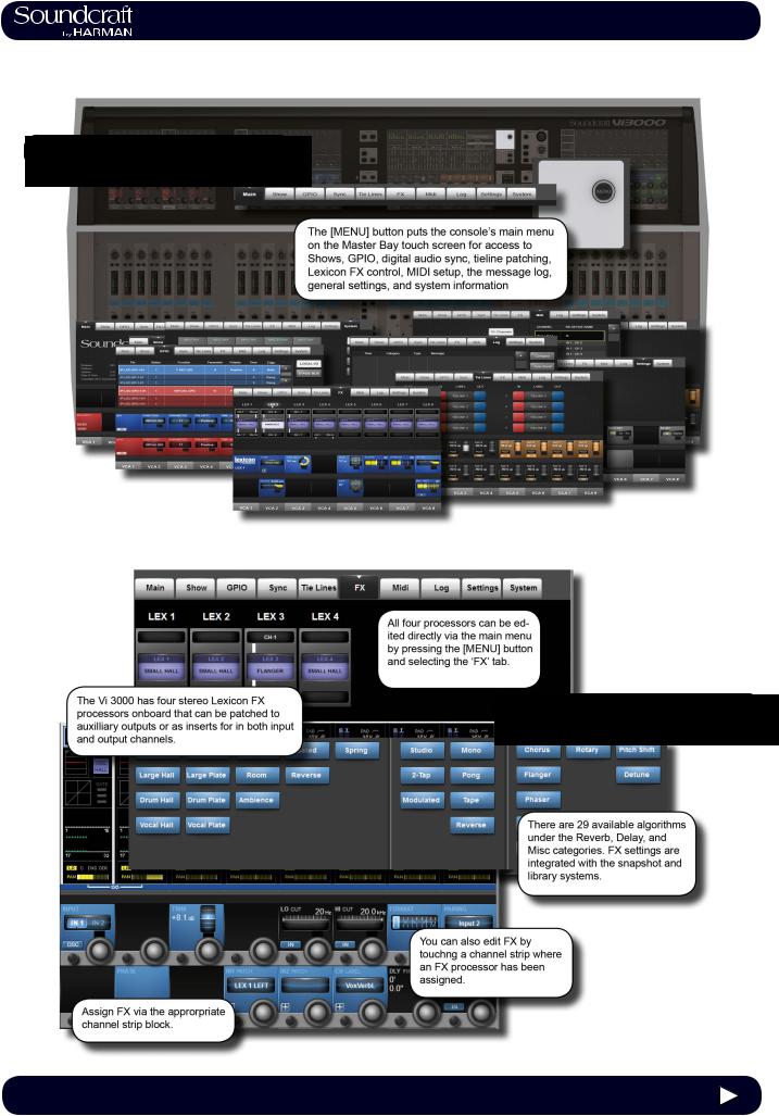
3.0 QUICK START |
Quick Start Guide
This chapter is a pictorial guide through the main concepts and functionality of the Vi3000 console.
Subsequent chapers go into these functions in more detail.
Console Sections
Vistonics II
3.0 - 1 |
3.0 QUICK START |
®
Vi3000 USER MANUAL |
3.0 QUICK START |
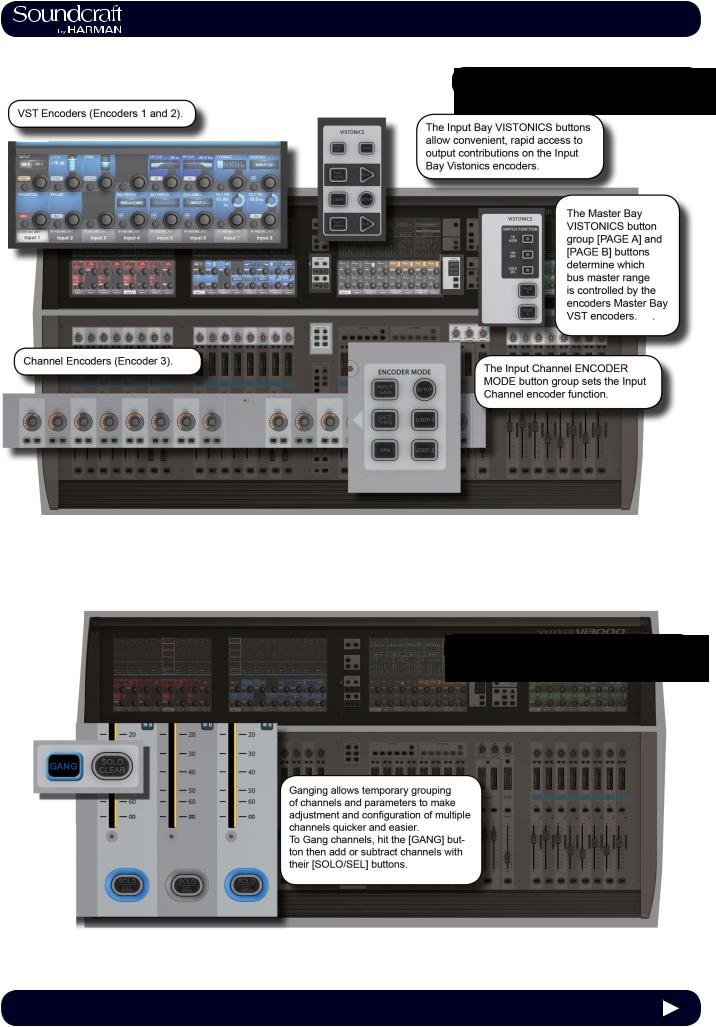
Buttons And Encoders
Ganging
3.0 - 2 |
3.0 QUICK START |
®
Vi3000 USER MANUAL |
3.0 QUICK START |
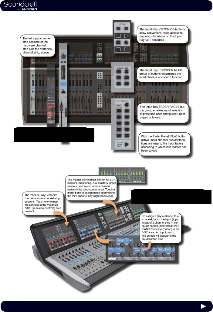
Inputs & Controls
Input Channel Access
3.0 - 3 |
3.0 QUICK START |
®
Vi3000 USER MANUAL |
3.0 QUICK START |
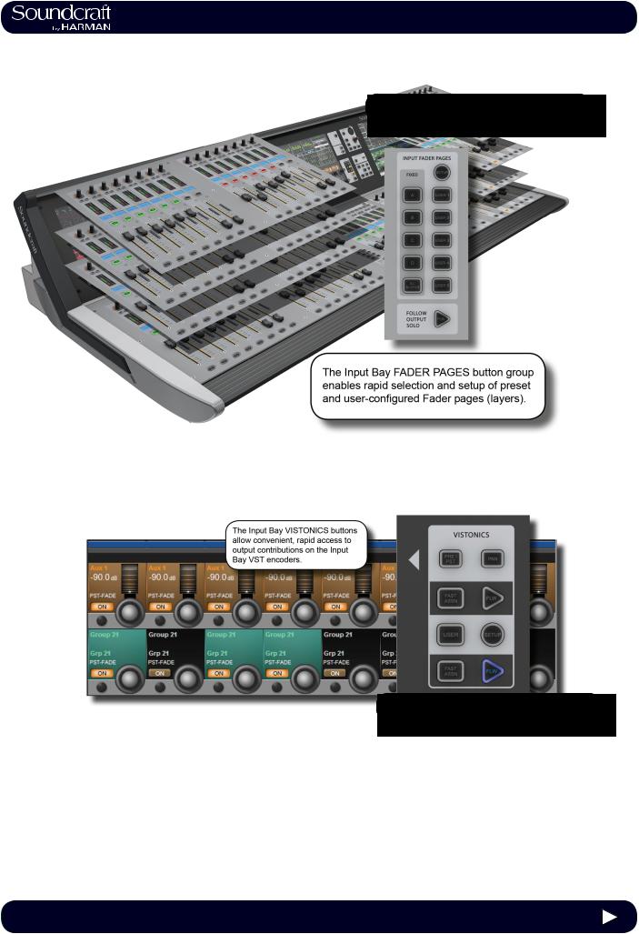
Fader Pages
Output Assignment
3.0 - 4 |
3.0 QUICK START |
®
Vi3000 USER MANUAL |
3.0 QUICK START |
Outputs & Control
3.0 - 5 |
3.0 QUICK START |
®
Vi3000 USER MANUAL |
3.0 QUICK START |
Monitoring
3.0 - 6 |
3.0 QUICK START |
®
Vi3000 USER MANUAL |
3.0 QUICK START |
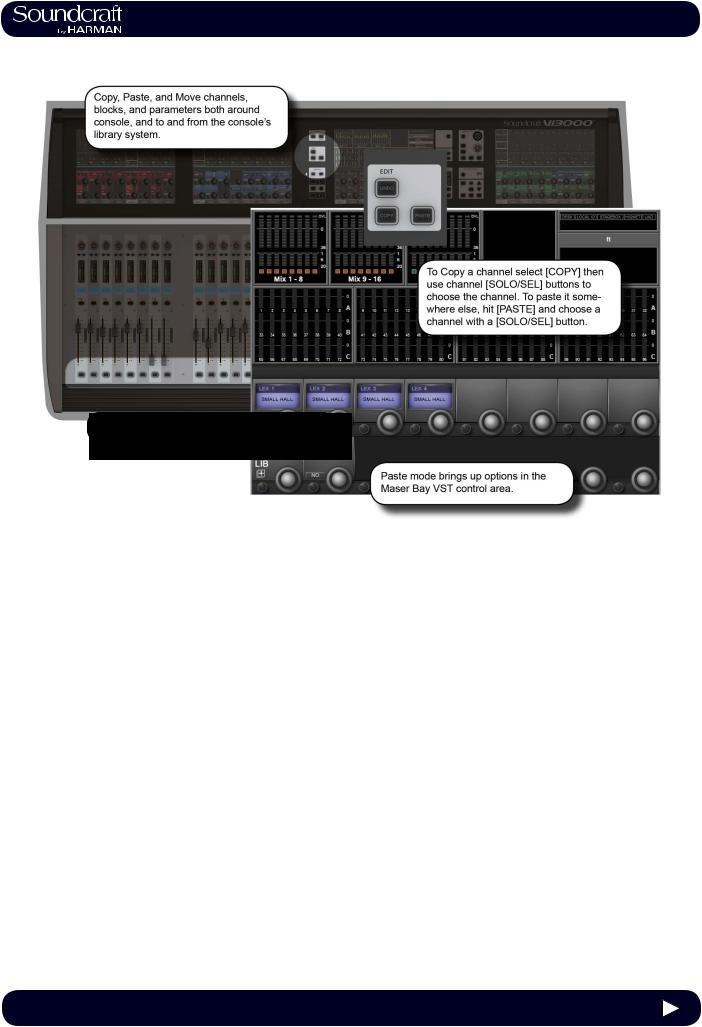
Copy, Paste, Move, LIbrary
3.0 - 7 |
3.0 QUICK START |
®
Vi3000 USER MANUAL |
3.0 QUICK START |
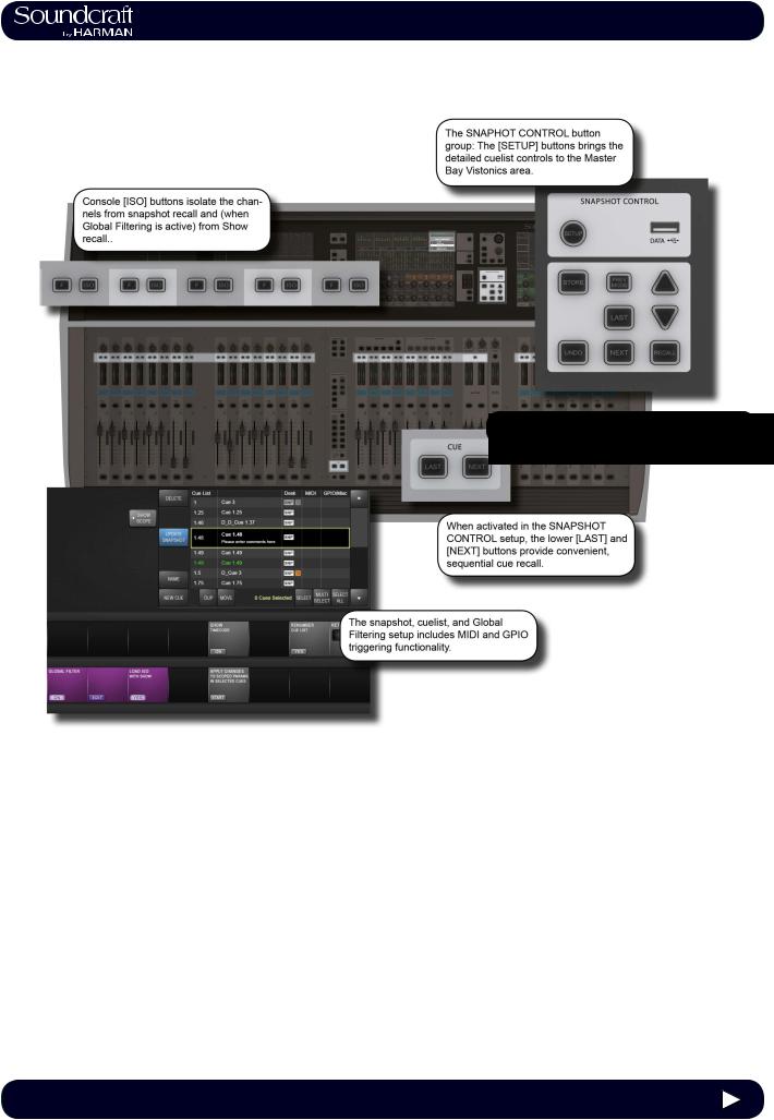
Snapshot & Cuelist
3.0 - 8 |
3.0 QUICK START |
®
Vi3000 USER MANUAL |
3.0 QUICK START |
Main Menu System
Lexicon FX
3.0 - 9 |
3.0 QUICK START |
®
Vi3000 USER MANUAL |
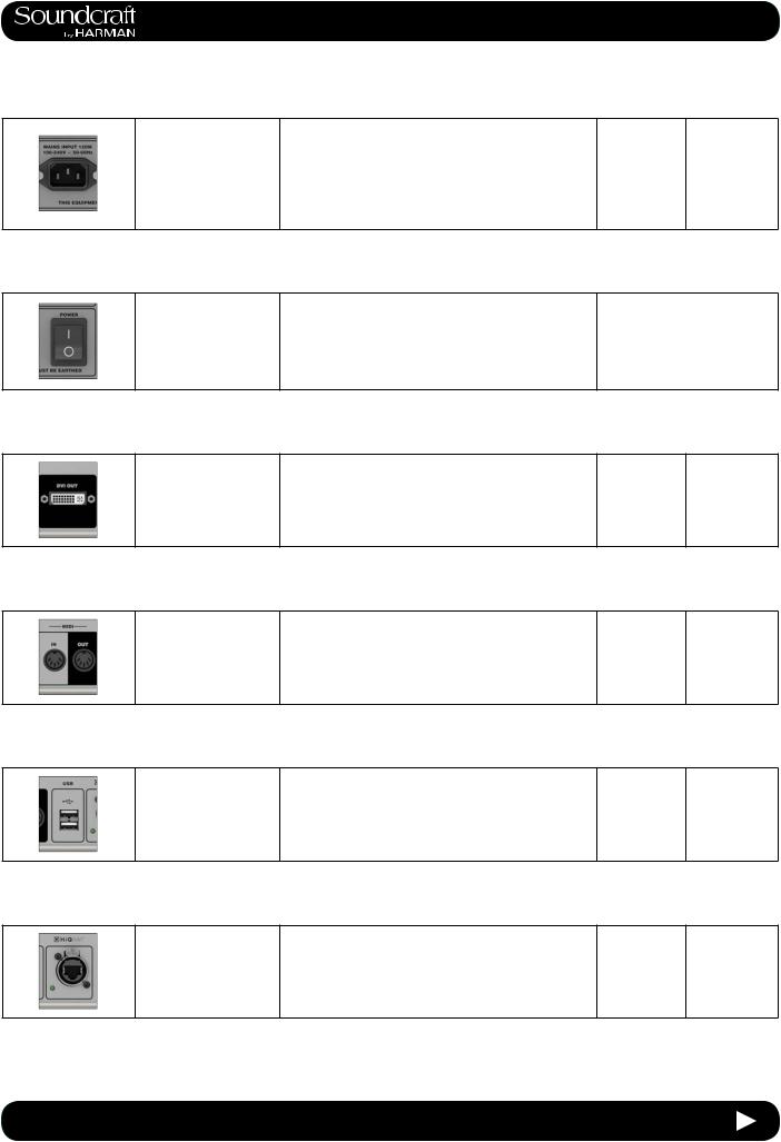
4.1: Hardware > Local I/O |
Hardware - Local I/O
Most of the Vi3000 local I/O is located on the rear panel of the console. The main I/O slots have a variety of possible configurations, inlcuding digital (AES) and analogue input and output cards. However, the monitor / masters output section cannot be changed - this contains the fixed-routing Monitor A and Monitor B outputs, plus the master LCR analogue outputs.
There are also user-configurable D21m I/O expansion slots that can accept any of the available Soundcraft D21m compatible I/O cards. Options for these include MADI (Optical or CAT 5), ADAT, Blu Link, Aviom, Ethersound, Cobranet, Line in, line out, AES/EBU, and mic in. The D21m IO Expansion slots are also used for connecting a Soundcraft Stagebox.
Fixed I/O on the rear panel includes all data/digital connections such as MIDI, USB, HiQnet, AES I/O, DANTE, MADI, Word Clock, and DVI Out, plus the dual redundant power supply connections.
There are also two 12v lamp connections.
The control surface of the console features two additional USB sockets and a talkback microphone XLR connection.
Main I/O Slots
The monitor / masters output section cannot be changed (bottom left of the main picture) as this contains the fixed-routing Monitor A and Monitor B outputs, plus the master LCR analogue outputs.
The main local I/O slots. Configuration options for the other slots are: 32 mic in/32 line outs, 48 mic in / 16 line out (the upper line out card
is replaced by a mic in 33-48 card), 16 mic in / 16 in 16 out AES / 16 line out (the mic in 1-16 card is replaced by a blank, the upper line out module 1-16 is replaced by a 16 in 16 out AES module).
4.1 |
4.1: Hardware > Local I/O |
®
Vi3000 USER MANUAL |
4.1: Hardware > Local I/O |
PSU / Power
Sockets
There are two mains inputs for seamless redundancy for those that require it. The IEC inlets can accept AC inputs from 100V to 240V.
Either socket can be used for a single supply. if both are used then one is a backup. The two sockets are labelled
PSU1 and PSU2, corresponding to indicator lights on the
Menu-System-Local page. The colour of this indicator, and the power button on front panel of the console, indicates the state of these PSUs: RED if only one of them is on, and GREEN if both are on.
Power
Switches
There is a power switch for each of the power supply inputs. Both need to be on for the dual redundancy switching to be effective.
DVI (Digital
Video) output
Inactive Active
Power off |
Power on |
|
|
For future use.
MIDI In / Out
5-Pin DIN connectors for MIDI compatible equipment only.
USB
The console USB connections ca be used for connecting an external keyboard or for USB storage devices.
HiQnet
Interface
XLR-housed EtherCon connector for HiQnet network connection.
For details on HiQnet setup, please refer to reference chapter 18.
4.1 |
4.1: Hardware > Local I/O |
®
Vi3000 USER MANUAL |
4.1: Hardware > Local I/O |
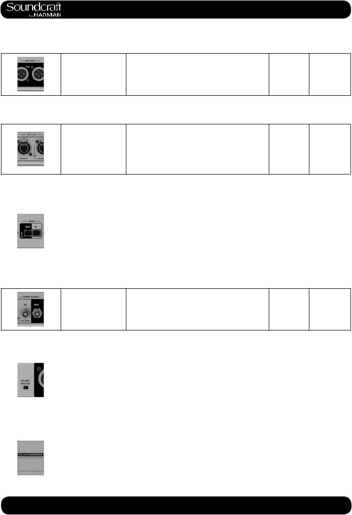
AES I/O
2 x 3-pin XLR AES (twochanel) digital audio input and output.
4 channels of AES/EBU format outputs and 4 channels of inputs.
AES 1-2 and 3-4 Input sockets have associated green confidence LEDs that indicate a valid sync signal is present.
DANTE
Input and output
Interface ports for a a DANTE (Audinate) digital audio network.
Please note, the Vi 3000 MADI local MADI and DANTE ports share an input and so are exclusive. That is, you can choose either a local MADI or DANTE input. The outputs are 'parallel' and a work concurrently. The choice between the MADI and DANTE inputs is determined by the DANTE/MADI global switch in the Setting tab of the main menu - accessed with the [MENU] button.
MADI I/O
|
|
Please note, the Vi 3000 MADI local MADI and DANTE |
|
|
|
|
ports share an input and so are exclusive. That is, you |
|
|
|
Input and output Inter- |
can choose either a local MADI or DANTE input. The |
|
|
|
face ports for connec- |
outputs are 'parallel' and a work concurrently. The choice |
|
|
|
tion to/from MADI-com- |
between the MADI and DANTE inputs is determined by |
|
|
|
patible equipment. |
the DANTE/MADI global switch in the Setting tab of the |
|
|
|
|
main menu - accessed with the [MENU] button. |
|
|
|
|
Connections are via multimode SC connectors. |
|
|
|
|
|
|
|
Wordclock I/O
Outputs console wordclock or syncs to external wordclock at 48kHz.
Talkback Mic
48V |
|
Inactive |
Active |
|
||
|
|
|
|
|
|
|
|
Switch to apply 48V |
|
|
|
|
|
|
phantom power to the |
|
|
phantom |
|
|
|
talkback mix input on |
|
No Power |
|
||
|
|
powered |
|
|||
|
the top panel of the |
|
|
|
||
|
|
|
|
|
|
|
|
console. |
|
|
|
|
|
|
|
|
|
|
|
|
D21m Slots |
|
|
|
|
|
|
|
|
|
|
|
|
|
|
|
These card slots can be used for any available D21m |
|
|
|
|
|
|
option cards of which there is a large range including |
|
|
|
|
|
|
MADI (Cat 5 or Optical) Stagebox connection, ADAT |
|
|
|
|
|
D21m Slots, labelled |
(16ch single slot), Blu Link (32ch single slot), Aviom (16 |
|
|
|
|
|
slots I, J, K, and L. |
ch single slot), Ethersound (64ch double slot), Cobranet |
|
|
|
|
|
|
(32ch single slot), Line in (8ch single slot), line out (8ch |
|
|
|
|
|
|
single slot), AES/EBU (16ch double slot), and mic in (4ch |
|
|
|
|
|
|
single slot). |
|
|
|
|
|
|
|
|
|
|
|
4.1 |
|
4.1: Hardware > Local I/O |
|
|
||
|
|
|||||
®
Vi3000 USER MANUAL 4.2: Hardware > DANTE / MADI Sources
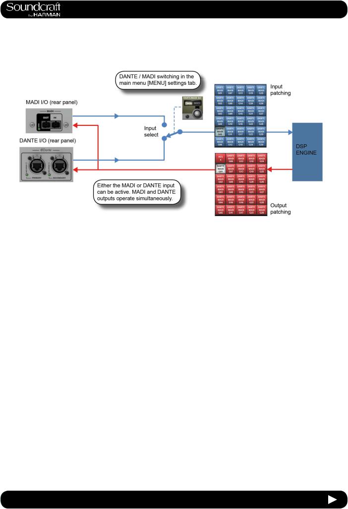
DANTE / MADI Interface and switching notes
The Dante/MADI interface gives the Vi3000 a lot of flexibility for recording shows, Virtual Soundchecking or interfacing with third party MADI or Dante-enabled equipment such as signal routers or system processors.
The interface comprises an input (64ch) in each format and an output (64ch) in each format. The outputs are fed by a common signal source which is available to any channel or bus via the Dante/MADI buttons within the Local tab of the console’s output patching matrix. The patched signal is fed to both Dante and MADI outputs simultaneously.
The inputs are selectable using a global switch in the Menu-Settings page of the console to choose either the Dante or the MADI port as the active input. Whichever of these is selected will appear in the Local tab of the input patch matrix in the console and will be labelled Dante or MADI as appropriate. Only one input can be used at a time.
Recording
64ch recording/replay is possible via the MADI interface using a third-party MADI interface such as RME MADIface, in most cases the recording software can be set to take its clock source from the console’s MADI stream. Alternatively the console’s Wordclock Out can be used to drive the recording software or router, or the console can be slaved to the other equipment’s clock via Wordclock In.
Alternatively, 64ch recording/replay can be achieved via the Dante port, by simply installing a copy of the Dante Virtual Soundcard driver (DVS), available from the Audinate website. A free one-off license token is included with every Vi3000 console -see the documentation packaged with the console. The license token number is used on the Audinate website to enable the issuing of a license key code which is then entered into the DVS boot screen to unlock the software. Dante Virtual Soundcard is available in PC and Mac formats and allows the the standard ethernet port on the computer to become visible as a 64ch input/output low-latency audio interface from any audio recording or processing software.
Interfacing to another Dante-enabled device or network
The Dante interface allows connection to any other Dante-enabled device, either directly or via a network switch, and using either normal or redundant connections depending on how the primary and secondary Dante ports of each device have been configured. Although the patching of signals to/from channels or busses in the console is done via the console’s patch matrix, the routing of those 64 in and out signals within the Dante network has to be set up using a free software application called Dante Controller, available from the Audinate website and running on either a PC or Mac external computer. Using this software it’s possible to make connections on an individual channel basis between the Vi3000’s 64ch Dante interface and all other Dante equipment on the network.
4.2 |
4.2: Hardware > DANTE / MADI Switching |

®
Vi3000 USER MANUAL 4.2: Hardware > DANTE / MADI Sources
Syncing with Dante equipment
Detailed setup of Dante network is beyond the scope of this User Guide (see user-guide documentation for Dante Controller software for more details), but it important to understand the concept of synchronisation within a Dante network, even if there are only two devices in the network. In any audio network there must be one device acting as clock master, the others are then slaves. In the Dante network, this device is known as the Primary Master. There can also be secondary masters - these are devices that are normally slaves but will take over the role of Master clock should the designated Master fail or be disconnected from the network. The status Primary/Secondary Master/Slave must be set for each device, including for the Vi3000, using external Dante Controller software - it cannot be done from within the console’s software. (Note: The Vi3000’s Dante interface is set as factory default to act as Primary Master).
The status of the Vi3000’s clock config must be setup to work correctly with the Dante interface, depending on whether the console is acting as Master or Slave on the network:
Console acting as Primary Master |
Select INT 48kHz clock in Menu-Sync page of console. Check ‘Slave to ext |
|
wordclock’ in Dante Controller software for Vi3000 Dante interface |
Console acting as Slave on Dante |
Select DANTE external clock in Menu-Sync page of console. Check ‘Slave to |
network. |
ext wordclock’ in Dante Controller software for Vi3000 Dante interface. |
Note: The option ‘Slave to External Wordclock’ in Dante Controller software is confusingly named as far as Vi3000 is concerned, it actually refers to whether the Dante interface itself within the Vi3000 is locked to an ‘external’ clock - in this case meaning the INTERNAL w/clock of the Vi3000 itself. If the Slave to Ext Worclock box is NOT checked, then it means the Dante I/F will sync to network clock, ie the clock of the Primary Master.
See Chapter 16: Main Menu, Sync page for further info.
4.2 |
4.2: Hardware > DANTE / MADI Sources |
®
Vi3000 USER MANUAL |
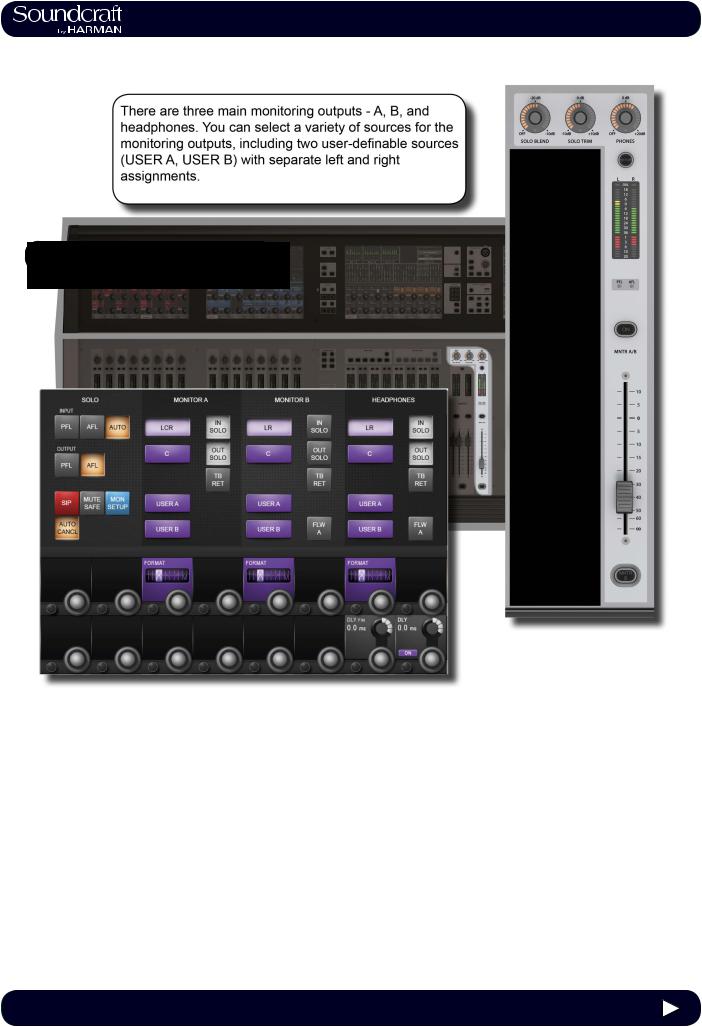
5.0 Operations Overview |
5.0: Operations Overview
5.0 |
5.0 Operations Overview |
®
Vi3000 USER MANUAL |
5.1 Operations Overview > Conventions |
5.1: Conventions And Colours
This manual, and the console uses certain conventions to make things significantly easier for the user. This includes the unique FaderGlow technology that can dynamically colour code console faders depending on their current assignment.
Conventions used in this manual
Three types of brackets are used to indicate the type of control being refered to.
[ ] is used to indicate a panel-mounted key or encoder.
{ } is used to indicate a Vistonics™ (VST) key or encoder.
( ) is used to indicate a button on a touch-screen.
COLOURS
The following table shows colours used in the VISTONICS screens, and in the headers and footers of the pages in this manual:
Audio Processing
Input Functions |
Blue |
|
Equaliser |
Red |
|
Filter |
Blue |
|
Gate,Comp,Lim,De- |
Green |
|
ess |
|
|
Pan, Dir Out, Insert |
Yellow |
|
Oscillator |
Gold |
|
Monitoring |
Lilac |
|
Busses |
|
|
|
|
|
Aux |
Orange |
|
Audio Group |
Green |
|
Matrix |
Cyan |
|
|
|
|
VCA/MG Indication
VCA 1..8 |
Blue |
VCA 9..16 |
Pink |
Aux VCA Master 1..16 |
White |
Mute Group |
Red |
Patching & Misc
Input Patch |
Blue |
Output Patch |
Red |
5.1 |
5.1 Operations Overview > Conventions |
|
®
Vi3000 USER MANUAL |
5.2 Operations Overview > Vistonics II |
5.2: Visonics Overview
Vistonics II is a unique control and display technology derived from the Studer Vistonics technology and exclusive to Soundcraft. The Vi3000 uses Vistonics II as a core technology for console operation because of its significant user-in- terface benefits.
The Vistonics screens are divided into two main areas. The top section is the touch screen area and serves a number of functions. For instance, in the default input chanel mode, the input touch screens show the Input, EQ, Dynamics, Bus outputs, and panning sections of input channel strip. Touching one of these opens that channel section onto the
Vistonics VST area.
The VST area is the lower section of the Vistonics screens, each with two rows of eight VST Fields. Each VST Field contains an encoder, a button, and a display area. VST Fields are normally used for individual parameter control. For instance, the default input Vistonics screen uses the upper row of encoders to control a channel’s contribution level to the Aux 1 bus, and the upper row of buttons to turn those contributions on and off.
5.2 |
5.2 Operations Overview > Vistonics II |
®
Vi3000 USER MANUAL |
5.2 Operations Overview > Vistonics II |
Buttons On/Off
If a function is assigned to a button it is displayed as shown. The 'active' state shows the button highlighted in a lighter colour.
Open Touch
Page
If the button can open a configuration page in the Touch area it shows a '+' sign on the button. If the configuration page is already open, the button will be labelled with a
'-' sign. Pressing the button in that state will exit the configuration page.
Inactive Fields
If an audio function block is disabled, with the background of the field changed to grey, the button indication will change to a darker colour.
5.2 |
5.2 Operations Overview > Vistonics II |
|
®
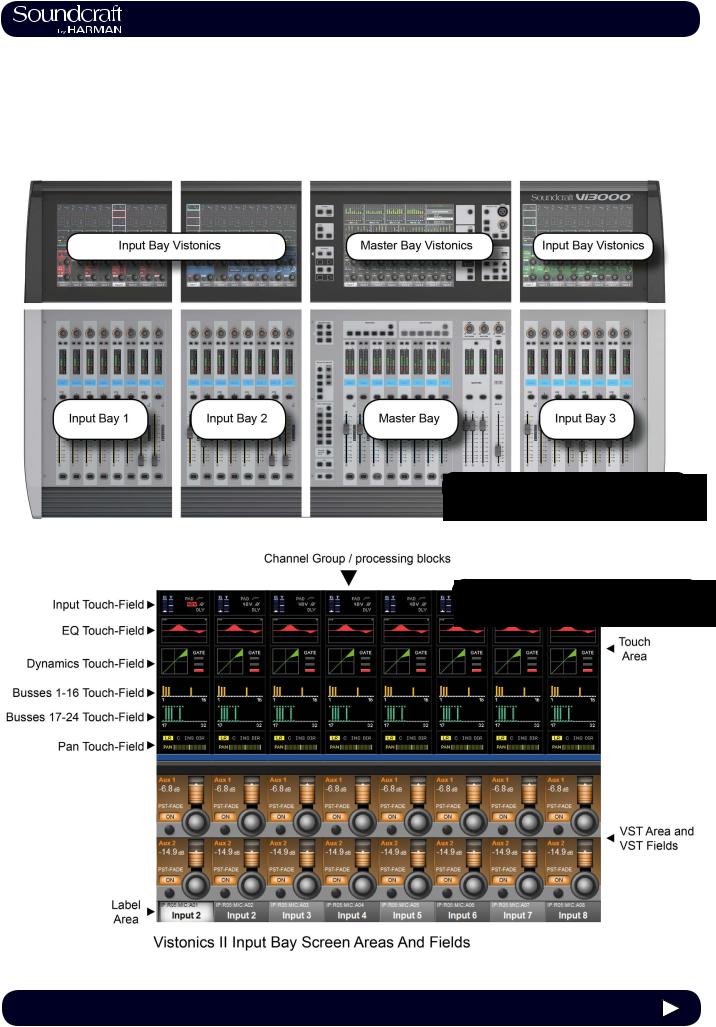
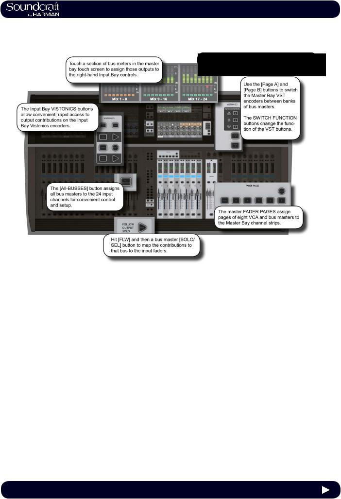
Vi3000 USER MANUAL 5.3 Operations Overview > Console Bays
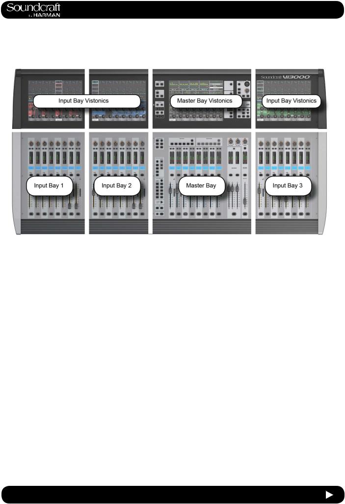
5.3: Console Bays
The Console is divided into four main bays. Counting from the left, the first, second, and fourth bays are Input Bays. The third bay is the Master Bay.
Input bays normally control input channels, however, they can have other functions mapped to them depending on how the console is being used. For example, you can map the bus masters, graphic EQ bands, matrix mix sources, aux bus contribtions, and more to the input faders.
The input bay vistonics touch screen areas normally show eight channel-strip processing blocks for the eight corresponding faders. You can touch those processing blocks to focus the VST section (bottom part of screen populated with encoders and buttons) on that selection.
The input bay VST areas normally show Aux 1 and 2 contributions, though the functions of these encoders are also determined by the input channel VISTONICS button group.
The Master Bay contains asignable faders for the bus masters, plus the mix master (L, R, C) faders and the assignable monitor fader.
The Master Bay touch screen default display is an overview of metering for all input and output channels, as well as an as system message area and cue list.
The Master Bay VST area’s default mapping is the first 16 bus masters. The next eight masters can be accessed with the [PAGE 2] button in the Master Bay VISTONICS button group.
5.3 |
5.3 Operations Overview > Console Bays |
 Loading...