


EFX8

1
User GuideUser Guide
User GuideUser Guide
User Guide
TM
TM

2
© Harman International Industries Ltd. 2007
All rights reserved
Parts of the design of this product may be protected by worldwide patents.
Part No. ZM0356-02
Soundcraft is a trading division of Harman International Industries Ltd. Informa-
tion in this manual is subject to change without notice and does not represent
a commitment on the part of the vendor. Soundcraft shall not be liable for any
loss or damage whatsoever arising from the use of information or any error
contained in this manual.
No part of this manual may be reproduced, stored in a retrieval system, or
transmitted, in any form or by any means, electronic, electrical, mechanical,
optical, chemical, including photocopying and recording, for any purpose with-
out the express written permission of Soundcraft.
Harman International Industries Limited
Cranborne House
Cranborne Road
POTTERS BAR
Hertfordshire
EN6 3JN
UK
Tel: +44 (0)1707 665000
Fax: +44 (0)1707 660742
http://www.soundcraft.com
E & OE.
IMPORTANT
Please read this manual carefully before using
your mixer for the first time.

3
Contents
SAFETY SYMBOL GUIDE 4
IMPORTANT SAFETY INSTRUCTIONS 5
INTRODUCTION 7
OVERVIEW 8
THE 60-SECOND GUIDE 8
WIRING UP 10
BLOCK DIAGRAM 14
MONO INPUT CHANNEL 15
STEREO INPUT CHANNELS 18
MASTER SECTION 21
Lexicon® FX PROCESSOR OVERVIEW 22
FX OPERATION 22
FX PROCESSOR CONTROLS 23
REVERBS 24
REVERB CONTROLS 25
DELAYS 26
DELAY CONTROLS 26
MODULATED EFFECTS 27
FACTORY RESET 29
EFFECTS DATA CHART 30
USING YOUR EFX CONSOLE 31
APPLICATIONS 33
GLOSSARY 36
TYPICAL CONNECTING LEADS 38
MARK-UP SHEETS 40
FITTING OPTIONAL RACKMOUNT EARS 42
TYPICAL SPECIFICATIONS 43
WARRANTY 44

4
For your own safety and to avoid invalidation of the warranty please read this
section carefully.
SAFETY SYMBOL GUIDE
For your own safety and to avoid invalidation of the warranty all text marked
with these symbols should be read carefully.
WARNINGS
The lightning flash with arrowhead symbol, is intended to
alert the user to the presence of un-insulated “dangerous
voltage” within the product’s enclosure that may be of suffi-
cient magnitude to constitute a risk of electric shock to
persons.
CAUTIONS
The exclamation point within an equilateral triangle is in-
tended to alert the user to the presence of important operat-
ing and maintenance (servicing) instructions in the literature
accompanying the appliance.
NOTES
Contain important information and useful tips on the opera-
tion of your equipment.
HEADPHONES SAFETY WARNING
Contain important information and useful tips on headphone
outputs and monitoring levels.
Recommended Headphone Impedance >= 150 Ohms.

5
IMPORTANT SAFETY INSTRUCTIONS
Read these instructions.
Keep these instructions.
Heed all warnings.
Follow all instructions.
Do not use this apparatus near water.
Clean only with a dry cloth.
Do not block any ventilation openings. Install in accordance with the manufacturer’s
instructions.
Do not install near any heat sources such as radiators, heat registers, stoves, or other
apparatus (including amplifiers) that produce heat.
Do not defeat the safety purpose of a polarised or grounding type plug. A polarised
plug has two blades with one wider than the other. A grounding type plug has two
blades and a third grounding prong. The wide blade or the third prong are provided for
your safety. If the provided plug does not fit into your outlet, consult an electrician for
replacement of the obsolete outlet
Protect the power cord from being walked on or pinched particularly at plugs, conven-
ience receptacles and the point where they exit from the apparatus.
Only use attachments/accessories specified by the manufacturer.
Use only with the cart, stand, tripod, bracket or table specified by the manufacturer, or
sold with the apparatus. When a cart is used, use caution when moving the cart/
apparatus combination to avoid injury from tip-over.
Unplug this apparatus during lightning storms or when unused for long periods of time.
Refer all servicing to qualified service personnel. Servicing is required when the appa-
ratus has been damaged in any way, such as power-supply cord or plug is damaged,
liquid has been spilled or objects fallen into the apparatus, the apparatus has been
exposed to rain or moisture, does not operate normally, or has been dropped.

6
NOTE: This equipment has been tested and found to comply with the limits for a Class A
digital device, pursuant to Part 15 of the FCC Rules. These limits are designed to provide
reasonable protection against harmful interference when the equipment is operated in a
commercial environment. This equipment generates, uses and can radiate radio frequency
energy and, if not installed and used in accordance with the instruction manual, may
cause harmful interference to radio communications. Operation of this equipment in a
residential area is likely to cause harmful interference in which case the user will be
required to correct the interference at his own expense.
This Class A digital apparatus meets the requirements of the Canadian Interference-Caus-
ing Equipment Regulations.
Cet appareil numérique de la Classe A respecte toutes les exigences du Règlement sur le
matériel brouilleur du Canada.
Note: It is recommended that all maintenance and service on the product should be
carried out by Soundcraft or its authorised agents. Soundcraft cannot accept any liability
whatsoever for any loss or damage caused by service, maintenance or repair by unauthor-
ised personnel.
WARNING: To reduce the risk of fire or electric shock, do not expose this apparatus to rain
or moisture.
Do not expose the apparatus to dripping or splashing and do not place objects filled with
liquids, such as vases, on the apparatus.
No naked flame sources, such as lighted candles, should be placed on the apparatus.
Ventilation should not be impeded by covering the ventilation openings with items such as
newspapers, table cloths, curtains etc.
THIS APPARATUS MUST BE EARTHED. Under no circumstances should the safety earth be
disconnected from the mains lead.
The mains supply disconnect device is the mains plug. It must remain accessible so as to
be readily operable when the apparatus is in use.
If any part of the mains cord set is damaged, the complete cord set should be replaced.
The following information is for reference only.
The wires in the mains lead are coloured in accordance with the following code:
Earth (Ground): Green and Yellow (US - Green/Yellow)
Neutral: Blue (US - White)
Live (Hot): Brown (US - Black)
As the colours of the wires in the mains lead may not correspond with the coloured
markings identifying the terminals in your plug, proceed as follows:
The wire which is coloured Green and Yellow must be connected to the terminal in
the plug which is marked with the letter E or by the earth symbol.
The wire which is coloured Blue must be connected to the terminal in the plug
which is marked with the letter N
The wire which is coloured Brown must be connected to the terminal in the plug
which is marked with the letter L
Ensure that these colour codes are followed carefully in the event of the plug being
changed
This unit is capable of operating over a range of mains voltages as marked on the rear
panel.

7
INTRODUCTION
Thank you for purchasing a Soundcraft EFX mixer. The EFX range is our most
cost-effective mixing solution, bringing you all the features and performance
that you expect from a Soundcraft product, at an extraordinarily low price.
The packaging, which your EFX arrived in, forms part of the product and must be
retained for future use.
Owning a Soundcraft console brings you the expertise and support of one of the
industry’s leading manufacturers, and the results of nearly 3 decades of sup-
porting some of the biggest names in the business. Our knowledge has been
attained through working in close contact with leading professionals and insti-
tutes to bring you products designed to get the best possible results from your
mixing.
Built to the highest standards using quality components and surface mount
technology, the EFX is designed to be as easy to use as possible. We have spent
years researching the most efficient methods of control for two key reasons:
1) Engineers, musicians, writers and programmers all need to have very few
interruptions to the creative process; our products have been designed to be
almost transparent, allowing this process to breathe.
2) Whether performing or recording, time is a very expensive and rare commod-
ity. Our products have a user interface which is recognised by millions to be the
industry standard because of its efficiency.
The sonic qualities of our products are exemplary - some of the same circuits
which are used on our most expensive consoles are employed in the EFX, bring-
ing you the great Soundcraft quality in a small format console without compro-
mise.
You will also be glad to know you have a one year warranty with your product
from the date of purchase. The EFX has been designed using the latest high-
end software based engineering packages. Every console from Soundcraft has
been proven to stand up to all the stress and rigours of modern day mixing
environments.
The entire EFX is manufactured using some of the most advanced techniques in
the world, from high density surface mount PCB technology, to computer aided
test equipment able to measure signals well outside the range of normal hear-
ing. As each console passes through to be quality checked before packing,
there is also a human listening station. Something we have learnt over the years
is that the human touch counts - and only by using people can you ensure the
product meets the high demands of the user.
ADVICE FOR THOSE WHO PUSH THE BOUNDARIES
Although your new console will not output any sound until you feed it signals, it
has the capability to produce sounds which when monitored through an ampli-
fier or headphones can damage hearing over time.
Please take care when working with your audio - if you are manipulating controls
which you don’t understand (which we all do when we are learning), make sure
your monitors are turned down. Remember that your ears are the most impor-
tant tool of your trade, look after them, and they will look after you.
Most importantly - don’t be afraid to experiment to find out how each parameter
affects the sound - this will extend your creativity and help you to get the best
from your mixer and the most respect from your artists and audience.
8
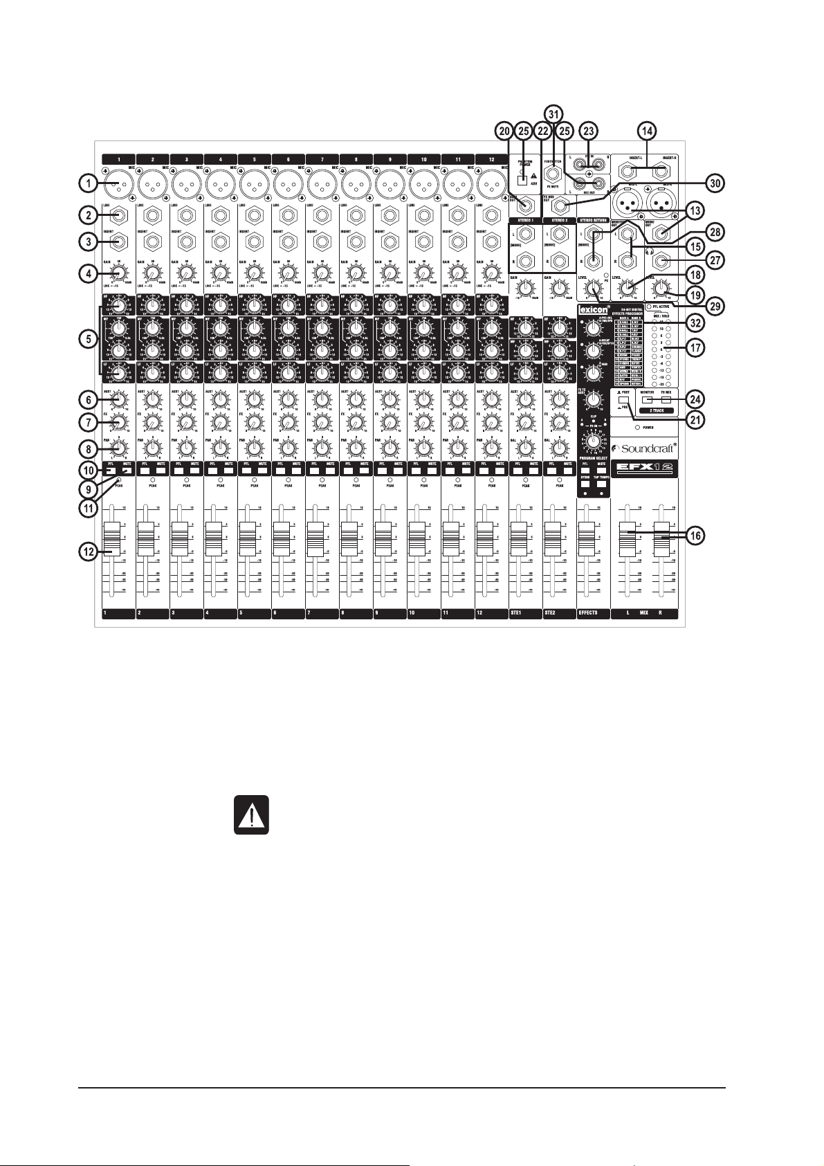
OVERVIEW
THE 60-SECOND GUIDE
1 MIC INPUT (XLR) Connect Microphones here. If you are using a condenser mic, ensure phan-
tom power is supplied by pressing the switch at the top of the master sec-
tion.
WARNING: Do Not apply Phantom Power before connecting a microphone.
2 LINE INPUT (¼” Jack) Connect Line level sources here, e.g. Synth, Drum Machine, DI etc.
3 INSERT POINT (¼” Jack) Connect Signal processors here, e.g. Compressor, Gate etc.
4 GAIN CONTROL Adjust this to increase or decrease the level of the incoming signal.
5 EQ STAGE Adjust these controls to change the signal tone (the character of the signal).
6 AUX 1 SEND Adjust this control to change the level of the signal to an artist’s monitors
(headphones/in-ear/stage monitors). Aux 1 is globally switchable pre/post
fade.
7 FX SEND This control sets the level of the post-fade signal being sent to the FX bus;
from there it is routed to the FX processor.
8 PAN CONTROL Use this control to position the signal within the stereo field.
9 MUTE SWITCH When this is pressed you will hear no signal from the channel (post-mute
signals).
To get you working as fast as possible, this manual begins with a 60-second guide. Here you can find quick
information on any feature of the console.

9
10 PFL When pressed the signal will appear on the monitor and headphone outputs
- use this to monitor the post-EQ signal from the channel.
11 PEAK LED This is used to indicate that the signal is close to distorting (clipping) on a
specific channel.
12 INPUT CHANNEL FADER This is used to control the level fed to the Mix Bus and post-fade sends.
13 MIX OUTPUTS (XLR) & MONO OUT (¼” Jack) Connect these to your analogue recording device, or to
your amplification system.
14 MIX INSERTS (¼” Jack) This is a pre-fade break in the signal path which can be used to feed a
dynamics or mastering device. The signal is sent from the tip of the jack plug
and the return path comes back in on the ring of the jack plug.
15 MONITOR O/Ps (¼” Jack) These are used to feed your monitoring system. This can be directly con-
nected to powered monitors, or indirectly via an amplifier to standard moni-
tors.
16 MASTER FADERS These faders control the overall level of the mix outputs.
17 MAIN METERS These show the level of the mix outputs. When the PFL ACTIVE LED is lit, the
meters show the level of the selected PFL signal.
18 MONITOR CONTROL This controls the level of the signal sent to your monitoring system.
19 PHONES CONTROL This controls the level of the signal sent to the headphones jack socket.
20 AUX 1 OUTPUT (¼” Jack) This output can be used to send the channel signal to an artist’s monitors
(headphones/in-ear/stage monitors). It is switchable pre/post fade.
21 AUX CONTROL This switch globally switches the AUX1 feed on all the input modules to be
either pre or post-fade.
22 STEREO INPUTS (¼” Jack) These two inputs can be used to connect line level stereo inputs from key-
boards, sound modules, samplers, computer based audio cards etc. These
inputs pass through a normal channel strip, with EQ, Auxes and a Balance
control.
23 2-TRACK INPUTS
(RCA Phono)
Here you can connect the playback from your recording device.
24 2-TRACK CONTROLS Use these to control the 2 Track signal. The MONITOR switch sends the signal
to the monitor outputs and phones, whilst the TO MIX switch sends it to the
main mix.
25 RECORD OUTPUTS
(RCA Phono)
You can connect these to the inputs of your recording device.
26 PHANTOM POWER Press this to switch the phantom power (48V) on for condenser microphones.
WARNING: Do Not apply Phantom Power before connecting a microphone.
27 HEADPHONES (¼” Jack) Plug your headphones into this socket. Recommended headphones imped-
ance is 150 ohms or greater.
28 STEREO RETURN INPUTS This pair of inputs accept 3-pole ‘A’ gauge (TRS) jacks. Use these inputs for
sources such as keyboards, drum machines, synths or CDs. The inputs are
BALANCED. Mono sources may be used by plugging into the left jack only.
29 STEREO RETURN CONTROL This control sets the level of signal routed to the main mix busses. There is
an associated PK LED to warn of signals which are too high.
30 FX BUS OUTPUT This output carries the signal from the FX bus. It could be used as a second
Aux Output if desired, if the FX Processor is not needed at the time. The FX
sends on the inputs channels to the FX bus are always post-fade.
31 FOOTSWITCH CONNECTOR This is used by the FX Processor, see page 23.
32 LEXICON® FX PROCESSOR See the information starting on page 22.
10
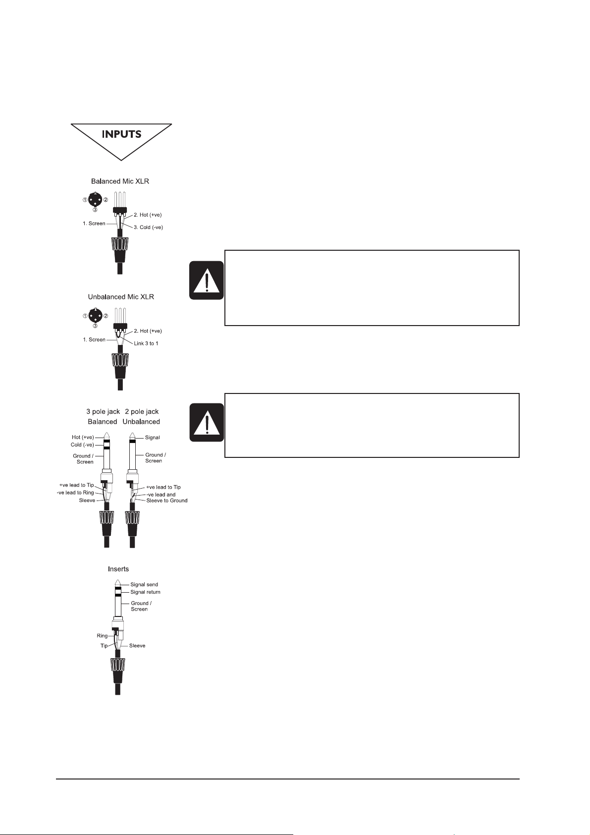
WIRING UP
Please refer to pages 38/39 for additional wiring details.
Mic Input
The MIC input accepts XLR-type connectors and is designed to suit a wide
range of BALANCED or UNBALANCED low-level signals, whether from deli-
cate vocals requiring the best low-noise performance, or drum kits needing
maximum headroom. Professional dynamic, condenser or ribbon mics are
best because these will be LOW IMPEDANCE. While you can use low-cost
HIGH IMPEDANCE mics, you do not get the same degree of immunity to
interference on the microphone cable and as a result the level of back-
ground noise may be higher. If you turn the PHANTOM POWER on, the socket
provides a suitable powering voltage for professional condenser mics.
The input level is set using the input GAIN knob.
The LINE input offers the same gain range as the MIC input, but at a higher
input impedance, and is 20dB less sensitive. This is suitable for most line
level sources.
Line Input
Accepts 3-pole ‘A’ gauge jacks, or 2-pole mono jacks which will automatically
ground the ‘cold’ input. Use this input for sources other than mics, such as
keyboards, drum machines, synths, tape machines or DI boxes. The input is
BALANCED for low noise and immunity from interference, but you can use
UNBALANCED sources by wiring up the jacks as shown, although you should
then keep cable lengths as short as possible to minimise interference pick-
up on the cable. Note that the ring must be grounded if the source is unbal-
anced. Set the input level using the GAIN knob, starting with the knob turned
fully anticlockwise. Unplug any MIC connection when using the LINE input.
Insert Point
The unbalanced, pre-EQ insert point is a break in the channel signal path,
allowing limiters, compressors, special EQ or other signal processing units
to be added in the signal path. The Insert is a 3-pole ‘A’ gauge jack socket
which is normally bypassed. When a jack is inserted, the signal path is
broken, just before the EQ section.
The signal from the channel appears on the TIP of the plug and is returned on
the RING, with the sleeve as a common ground.
The Send may be tapped off as an alternative pre-fade, pre-EQ direct output
if required, using a lead with tip and ring shorted together so that the signal
path is not interrupted.
WARNING !
Start with the input GAIN knob turned fully anticlockwise when
plugging high level sources into the LINE input to avoid overloading
the input channel or giving you a very loud surprise!
DO NOT use UNBALANCED sources with the phantom power
switched on. The voltage on pins 2 & 3 of the XLR connector may
cause serious damage. BALANCED dynamic mics may normally be
used with phantom power switched on (contact your microphone
manufacturer for guidance)
11
Stereo Inputs STEREO 1/2
These accept 3-pole ‘A’ gauge jacks, or 2-pole mono jacks which will automati-
cally ground the ‘cold’ input. Use these inputs for sources such as keyboards,
drum machines, synths, tape machines or as returns from processing units.
The input is BALANCED for low noise and immunity from interference, but you
can use UNBALANCED sources by wiring up the jacks as shown, although you
should then keep cable lengths as short as possible to minimise interference
pick-up on the cable. Note that the ring must be grounded if the source is
unbalanced.
Mono sources can be fed to both paths by plugging into the Left jack only.
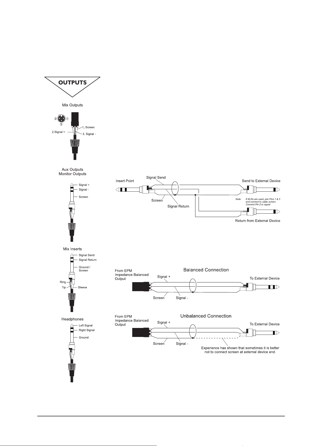
Mix Inserts
The unbalanced, pre-fade Mix insert point is a break in the output signal path
to allow the connection of, for example, a compressor/limiter or graphic equal-
iser. The Insert is a 3-pole ‘A’ gauge jack socket which is normally bypassed.
When a jack is inserted, the signal path is broken, just before the mix fader.
The mix signal appears on the TIP of the plug and is returned on the RING. A
‘Y’ lead may be required to connect to equipment with separate send and
return jacks as shown below:
Mix Outputs
The MIX outputs are on XLR’s, wired as shown, and incorporate impedance
balancing, allowing long cable runs to balanced amplifiers and other equip-
ment.
Aux & FX Bus Outputs
The Aux & FX Bus outputs are on 3-pole ‘A’ gauge jack sockets, wired as shown
on the left, and are balanced, allowing long cable runs to balanced amplifiers
and other equipment.
12
Headphones
The PHONES output is a 3-pole ‘A’ gauge jack, wired as a stereo output as shown,
ideally for headphones of 150Ω or greater. 8Ω headphones are not recommended.
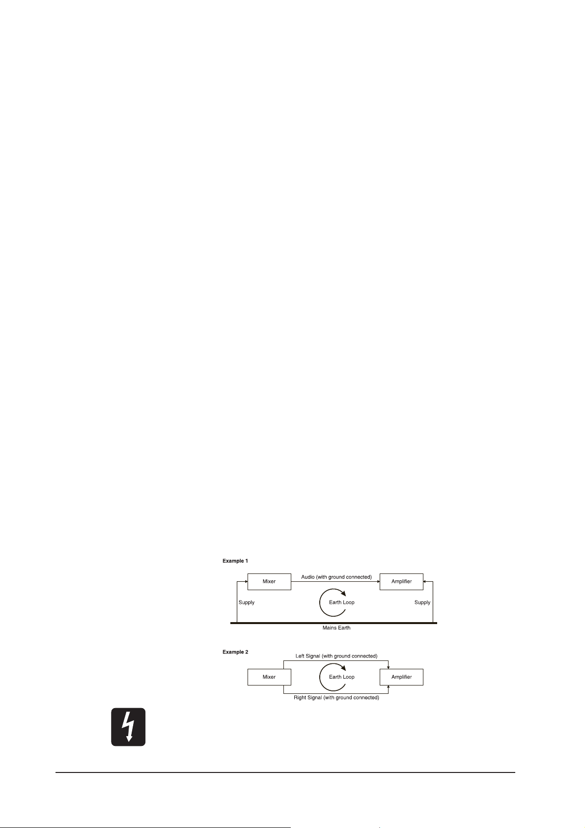
Polarity (Phase)
You will probably be familiar with the concept of polarity in electrical signals and this is
of particular importance to balanced audio signals. Just as a balanced signal is highly
effective at cancelling out unwanted interference, so two microphones picking up the
same signal can cancel out, or cause serious degradation of the signal if one of the
cables has the +ve and -ve wires reversed. This phase reversal can be a real problem
when microphones are close together and you should therefore always take care to
connect pins correctly when wiring audio cables.
Grounding and Shielding
For optimum performance use balanced connections where possible and ensure that
all signals are referenced to a solid, noise-free earthing point and that all signal cables
have their screens connected to ground. In some unusual circumstances, to avoid earth
or ground ‘loops’ ensure that all cable screens and other signal earths are connected to
ground only at their source and not at both ends.
If the use of unbalanced connections is unavoidable, you can minimise noise by follow-
ing these wiring guidelines:
• On INPUTS, unbalance at the source and use a twin screened cable as though it
were balanced.
• On OUTPUTS, connect the signal to the +ve output pin, and the ground of the
output device to -ve. If a twin screened cable is used, connect the screen only at
the mixer end.
• Avoid running audio cables or placing audio equipment close to thyristor
dimmer units or power cables.
• Noise immunity is improved significantly by the use of low impedance sources,
such as good quality professional microphones or the outputs from most modern
audio equipment. Avoid cheaper high impedance microphones, which may suffer
from interference over long cable runs, even with well-made cables.
Grounding and shielding is still seen as a black art, and the suggestions above are only
guidelines. If your system still hums, an earth/ground loop is the most likely cause. Two
examples of how an earth loop can occur are shown below.
Warning!
Under NO circumstances must the AC power mains earth be disconnected from the
mains lead.
13
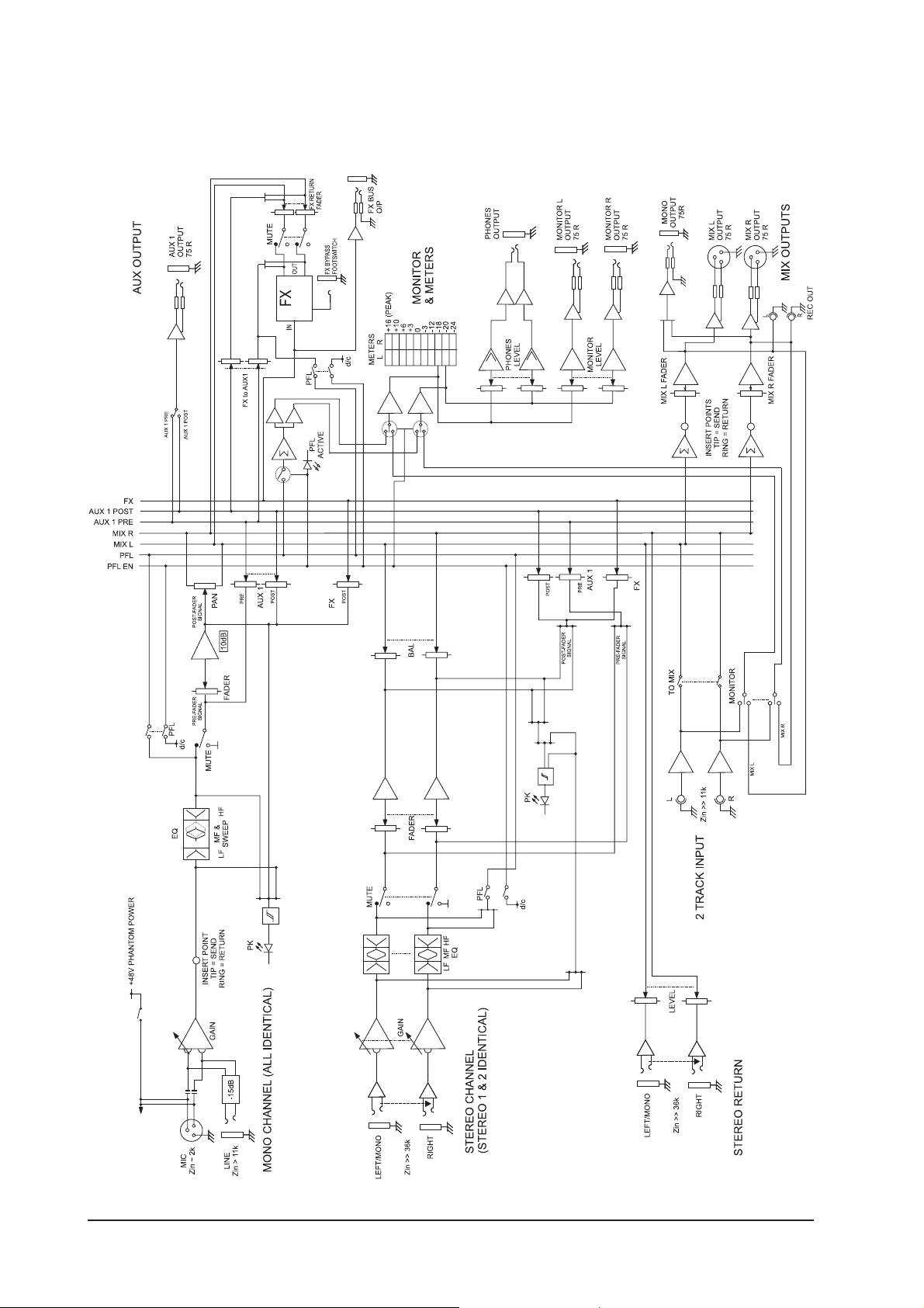
PROBLEM SOLVING
Basic problem solving is within the scope of any user if a few basic rules are followed.
• Get to know the Block Diagram of your console (see page 14).
• Get to know what all controls and/or connections in the system are supposed
to do.
• Learn where to look for common trouble spots.
The Block Diagram is a representative sketch of all the components of the console,
showing how they connect together and how the signal flows through the system.
Once you have become familiar with the various component blocks you will find the
Block Diagram is quite easy to follow and you will have gained a valuable understand-
ing of the internal structure of the console.
Each component has a specific function and only by getting to know what each part is
supposed to do will you be able to tell if there is a genuine fault! Many “faults” are the
result of incorrect connection or control settings which may have been overlooked.
Basic Troubleshooting is a process of applying logical thought to the signal path through
the console and tracking down the problem by elimination.
• Swap input connections to check that the source is really present. Check both
Mic and Line inputs.
• Eliminate sections of the channel by using the insert point to re-route the signal
to other inputs that are known to be working.
• Route channels to different outputs or to auxiliary sends to identify problems
on the Master section.
• Compare a suspect channel with an adjacent channel which has been set up
identically. Use PFL to monitor the signal in each section.
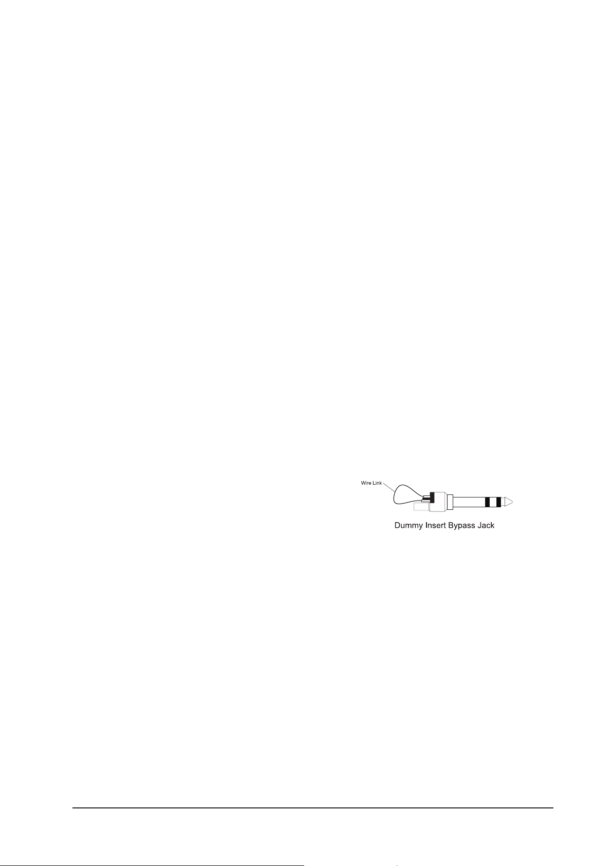
• Insert-point contact problems may be checked by using an insert bypass jack
with tip and ring shorted together as shown below. If the signal appears when
the jack is inserted it shows that there is a problem with the normalling con-
tacts on the jack socket, caused by wear or damage, or often just dirt or dust.
Keep a few in your gig tool box.
If in doubt please contact Soundcraft customer support.
PRODUCTS UNDER WARRANTY
UK customers should contact their local dealer.
Customers outside the UK are requested to contact their territorial distributor who is
able to offer support in the local time zone and language. Please see the distributor
listings on our website (www.soundcraft.com) to locate your local distributor.
OUT-OF-WARRANTY PRODUCTS
For out-of-warranty consoles purchased in the United Kingdom, please contact the
Customer Services Department (e-mail: csd@soundcraft.com) at the factory in Pot-
ters Bar, Hertfordshire: Telephone +44 (0)1707 665000.
For all other out-of-warranty consoles, please contact the appropriate territorial dis-
tributor.
When mailing or faxing please remember to give as much information as possible.
This should include your name, address and a daytime telephone number. Should you
experience any difficulty please contact Customer Services Department (e-mail:
csd@soundcraft.com)
14
BLOCK DIAGRAM
 Loading...