


Soundcraft Vi4™
User Guide
®
Soundcraft Vi4™ User Guide |
i |

IMPORTANT
Please read this manual carefully before using your mixer for the first time.
This equipment complies with the EMC directive 2004/108/EC and LVD 2006/95/EC
This product is approved to safety standards
IEC 60065:2001 (Seventh Edition) +A1:2005
EN60065:2002 +A11:2008
UL60065-03
CAN/CSA-E60065-03
And EMC standards
EN55103-1: 1996 (E2)
EN55103-2: 1996 (E2)
Warning: Any modification or changes made to this device, unless explicitly approved by Harman, will invalidate the authorisation of this device. Operation of an unauthorised device is prohibited under Section 302 of the Communications act of 1934, as amended, and Subpart 1 of Part 2 of Chapter 47 of the Code of Federal Regulations.
NOTE: This equipment has been tested and found to comply with the limits for a Class B digital device, pursuant to Part 15 of the FCC Rules. These limits are designed to provide reasonable protection against harmful interference in a residential installation. This
equipment generates, uses and can radiate radio frequency energy and, if not installed and used in accordance with the instructions, may cause harmful interference to radio communications. However, there is no guarantee that interference will not occur in a particular installation. If this equipment does cause harmful interference to radio or television reception, which can be determined by turning the equipment off and on, the user is encouraged to try to correct the interference by one or more of the following measures:
*Reorient or relocate the receiving antenna
*Increase the separation between the equipment and the receiver
*Connect the equipment into an outlet on a circuit different from that to which the receiver is connected.
*Consult the dealer or an experienced radio/TV technician for help
For further details contact
Harman International Industries Ltd, Cranborne House, Cranborne Road, Potters Bar, Hertfordshire EN6 3JN, UK Telephone +44(0) 1707 665000 Fax +44 (0)1707 660742 email: soundcraft@harman.com
© Harman International Industries Ltd. 2010 All rights reserved
Parts of the design of this product may be protected by worldwide patents. Part No. Part No. ZM0353-01 Rev3 Issue 0910
E&OE September 2010
Soundcraft is a trading division of Harman International Industries Ltd. Information in this manual is subject to change without notice and does not represent a commitment on the part of the vendor. Soundcraft shall not be liable for any loss or damage whatsoever arising from the use of information or any error contained in this manual.
No part of this manual may be reproduced, stored in a retrieval system, or transmitted, in any form or by any means, electronic, electrical, mechanical, optical, chemical, including photocop-
ying and recording, for any purpose without the express written permission of Soundcraft.
Harman International Industries Limited
Cranborne House, Cranborne Road, Potters Bar, Hertfordshire, EN6 3JN, UK Tel: +44 (0)1707 665000
®Fax: +44 (0)1707 660742 http://www.soundcraft.com
ii |
Soundcraft Vi4™ User Guide |

Contents |
|
INTRODUCTION |
1-1 |
SAFETY NOTICES ................................................................................................................ |
1-1 |
SAFETY SYMBOL GUIDE ..................................................................................................... |
1-1 |
IMPORTANT SAFETY WARNINGS ......................................................................................... |
1-2 |
WARNINGS ......................................................................................................................................... |
1-3 |
WORKING SAFELY WITH SOUND.......................................................................................... |
1-4 |
WARRANTY ........................................................................................................................ |
1-4 |
Soundcraft Vi4™ FEATURES AND SPECIFICATIONS .............................................................. |
1-5 |
Audio Channels .................................................................................................................................. |
1-5 |
I/O Capability .................................................................................................................................... |
1-5 |
Miscellaneous .................................................................................................................................... |
1-6 |
Channel Processing ............................................................................................................................ |
1-6 |
Control Surface .................................................................................................................................. |
1-7 |
CONSOLE OVERVIEW .......................................................................................................... |
1-8 |
Bays ................................................................................................................................................... |
1-8 |
Layers ................................................................................................................................................ |
1-9 |
Encoders .......................................................................................................................................... |
1-10 |
Master Audio Functions .................................................................................................................... |
1-11 |
Master Control ................................................................................................................................. |
1-12 |
SYSTEM COMPONENTS |
2-1 |
SYSTEM HARDWARE OVERVIEW ......................................................................................... |
2-2 |
NOTE ON INSTALLATION OF THE COOLING FANS/FILTERS .................................................... |
2-3 |
THE CONSOLE REAR CONNECTORS ..................................................................................... |
2-4 |
Mains Power Supply Inlet .................................................................................................................... |
2-4 |
Audio And Data Rearcon ..................................................................................................................... |
2-4 |
LOCAL RACK ...................................................................................................................... |
2-6 |
Local Rack Description ....................................................................................................................... |
2-6 |
How It Works ...................................................................................................................................... |
2-6 |
Front Panel ......................................................................................................................................... |
2-6 |
Local Rack Rear ................................................................................................................................. |
2-7 |
Card Function Overview ..................................................................................................................... |
2-10 |
STAGE BOX ...................................................................................................................... |
2-13 |
Stage Box Description ....................................................................................................................... |
2-13 |
Card Function Overview ..................................................................................................................... |
2-13 |
Redundant MADI Cable Operation ..................................................................................................... |
2-14 |
Front Panel ....................................................................................................................................... |
2-15 |
CONNECTING THE PARTS OF THE SYSTEM ......................................................................... |
2-16 |
OPERATION OVERVIEW |
3-1 |
GENERAL RULES ................................................................................................................ |
3-1 |
CONVENTIONS USED IN THIS MANUAL ................................................................................ |
3-1 |
SCREENS .......................................................................................................................... |
3-1 |
Input Screens ..................................................................................................................................... |
3-1 |
Screen Colour Codes .......................................................................................................................... |
3-2 |
VISTONICS II™ KNOBS ....................................................................................................... |
3-3 |
AUDIO FUNCTION STATES ................................................................................................... |
3-3 |
MOMENTARY/LATCHING CONTROL ACTION ......................................................................... |
3-3 |
SOLO/SEL KEYS ................................................................................................................ |
3-4 |
LABELLING ........................................................................................................................ |
3-4 |
General .............................................................................................................................................. |
3-4 |
Channel Labels ................................................................................................................................... |
3-5 |
Soundcraft Vi4™ User Guide |
iii |

BUS CONFIGURATION ........................................................................................................ |
3-6 |
GANG ................................................................................................................................ |
3-7 |
General .............................................................................................................................................. |
3-7 |
Creating A Gang ................................................................................................................................. |
3-7 |
Switching-Off Gang Mode ................................................................................................................... |
3-7 |
Clearing A Gang .................................................................................................................................. |
3-7 |
Gang All Input Channels ..................................................................................................................... |
3-7 |
INPUT |
4-1 |
SIGNAL FLOW .................................................................................................................... |
4-1 |
INPUT CHANNEL STRIP ...................................................................................................... |
4-2 |
INPUT CHANNEL TOUCH FIELDS ......................................................................................... |
4-3 |
Change A Parameter Of An Input Channel ............................................................................................ |
4-3 |
INPUT ................................................................................................................................ |
4-4 |
INPUT field ......................................................................................................................................... |
4-4 |
GAIN field .......................................................................................................................................... |
4-5 |
TRIM field .......................................................................................................................................... |
4-5 |
LO CUT field ....................................................................................................................................... |
4-5 |
HI CUT field ........................................................................................................................................ |
4-5 |
FORMAT field ...................................................................................................................................... |
4-5 |
PAIRING field ..................................................................................................................................... |
4-5 |
PHANTOM field ................................................................................................................................... |
4-5 |
PHASE field ........................................................................................................................................ |
4-5 |
IN1 PATCH field .................................................................................................................................. |
4-5 |
IN2 PATCH field .................................................................................................................................. |
4-5 |
CH Label field ..................................................................................................................................... |
4-5 |
DLY field ............................................................................................................................................. |
4-5 |
STEREO CONFIGURATION ................................................................................................... |
4-6 |
Pairing of input channels .................................................................................................................... |
4-6 |
Pair An input Channel ......................................................................................................................... |
4-6 |
Stereo Busses .................................................................................................................................... |
4-7 |
EQUALISER ........................................................................................................................ |
4-8 |
General .............................................................................................................................................. |
4-8 |
Equaliser Band Highlight .................................................................................................................... |
4-9 |
BAND Field ......................................................................................................................................... |
4-9 |
SHELF Switch ..................................................................................................................................... |
4-9 |
EQUALISER Field ................................................................................................................................ |
4-9 |
DYNAMICS....................................................................................................................... |
4-10 |
General ............................................................................................................................................ |
4-10 |
GATE Function .................................................................................................................................. |
4-10 |
DE-ESS Function ............................................................................................................................... |
4-12 |
COMPRESSOR Function .................................................................................................................... |
4-13 |
LIMITER Function .............................................................................................................................. |
4-13 |
MKUP ............................................................................................................................................... |
4-13 |
BUS ................................................................................................................................ |
4-14 |
General ............................................................................................................................................ |
4-14 |
AUX (Mono) ...................................................................................................................................... |
4-14 |
AUX (Stereo) .................................................................................................................................... |
4-14 |
GRP (Mono) ..................................................................................................................................... |
4-14 |
GRP (Stereo) .................................................................................................................................... |
4-14 |
Empty ............................................................................................................................................... |
4-14 |
PANNING ......................................................................................................................... |
4-15 |
General ............................................................................................................................................ |
4-15 |
PAN Function LR Mode ...................................................................................................................... |
4-15 |
PAN Function LCR Mode ................................................................................................................... |
4-16 |
........................................................................................................................................................ |
4-16 |
AUDIO FORMAT ................................................................................................................ |
4-17 |
General ............................................................................................................................................ |
4-17 |
iv |
Soundcraft Vi4™ User Guide |
Input Channels ................................................................................................................................. |
4-17 |
Mix Busses ....................................................................................................................................... |
4-17 |
Masters ............................................................................................................................................ |
4-17 |
PAN/BAL .......................................................................................................................................... |
4-18 |
INSERT Function ............................................................................................................................... |
4-19 |
Direct Out Function ........................................................................................................................... |
4-19 |
OUTPUTS |
5 - 1 |
SIGNAL FLOW .................................................................................................................. |
5 - 1 |
GENERAL ......................................................................................................................... |
5 - 2 |
L,R & C Master Processing ................................................................................................................ |
5 - 3 |
MASTER EQ LINKING (V2.0 Software and above) .............................................................. |
5 - 4 |
Default settings ................................................................................................................................ |
5 - 4 |
MASTER BAY OUTPUT STRIPS........................................................................................... |
5 - 5 |
Bus Master Processing ..................................................................................................................... |
5 - 6 |
INPUT BAY STRIP USING [ALL BUSSES]............................................................................ |
5 - 7 |
MASTER BAY VISTONICS™ ENCODERS & KEYS ................................................................. |
5 - 8 |
VST Key Function .............................................................................................................................. |
5 - 8 |
CHANGING OUTPUT BUS PARAMETERS ............................................................................ |
5 - 9 |
Changing A Parameter Of A Bus ........................................................................................................ |
5 - 9 |
EQUALISER .................................................................................................................... |
5 - 10 |
DYNAMIC ....................................................................................................................... |
5 - 11 |
PAN ............................................................................................................................... |
5 - 12 |
LOW CUT Field ................................................................................................................................ |
5 - 12 |
PHASE Field ................................................................................................................................... |
5 - 12 |
DLY Field ........................................................................................................................................ |
5 - 12 |
MATRIX |
6-1 |
SIGNAL FLOW .................................................................................................................... |
6-1 |
FUNCTION ......................................................................................................................... |
6-1 |
Adjusting A Matrix Send Level ............................................................................................................. |
6-3 |
MATRIX CONFIGURATION ................................................................................................... |
6-3 |
SOURCE field ..................................................................................................................................... |
6-3 |
MTX Point Field .................................................................................................................................. |
6-4 |
ENCODERS |
7-1 |
GENERAL INTRODUCTION ................................................................................................... |
7-1 |
CHANNEL ENCODERS ........................................................................................................ |
7-2 |
CHANNEL VST ENCODER 1& 2 ............................................................................................ |
7-3 |
VST Encoder Priority ............................................................................................................................ |
7-3 |
Changing Encoder Function ................................................................................................................ |
7-4 |
MASTER BAY PANEL ENCODERS ......................................................................................... |
7-5 |
MASTER BAY VST ENCODERS ............................................................................................. |
7-5 |
Master Vistonics Switch Function Panel .............................................................................................. |
7-6 |
LAYERING (FADER PAGES) |
8-1 |
GENERAL ........................................................................................................................... |
8-1 |
INPUTS .............................................................................................................................. |
8-1 |
Temporary Layer .................................................................................................................................. |
8-2 |
OUTPUTS ........................................................................................................................... |
8-3 |
Master Fader section .......................................................................................................................... |
8-3 |
ALL Busses ......................................................................................................................................... |
8-4 |
VST Master Area ................................................................................................................................. |
8-5 |
VCA & MUTE GROUPS |
9-1 |
VCA/MUTE GROUP INDICATION ......................................................................................... |
9-1 |
MUTE GROUP MASTER SWITCHES ...................................................................................... |
9-2 |
VCA CONTROL GROUP BEHAVIOUR ..................................................................................... |
9-2 |
|
|
Soundcraft Vi4™ User Guide |
v |

AUDIO BEHAVIOUR ............................................................................................................ |
9-2 |
ASSIGNING VCAs ............................................................................................................... |
9-3 |
ASSIGNING MUTE GROUPS ................................................................................................ |
9-3 |
ASSIGNING VCAS AND MUTE GROUPS TO OUTPUT CHANNELS ............................................. |
9-3 |
VCA GROUPS WHEN AUX SENDS ARE CONTROLLED BY CHANNEL FADERS ........................... |
9-3 |
Procedure ........................................................................................................................................... |
9-4 |
PATCH SYSTEM |
10-1 |
SIGNAL FLOW .................................................................................................................. |
10-1 |
OVERVIEW ....................................................................................................................... |
10-2 |
GENERAL RULES .............................................................................................................. |
10-2 |
INPUT .............................................................................................................................. |
10-3 |
Patch A Source To An Input Channel .................................................................................................. |
10-4 |
Using A Spare Mic For Several Inputs ................................................................................................ |
10-4 |
OUTPUT ........................................................................................................................... |
10-5 |
Patch a BUS to an OUTPUT ............................................................................................................... |
10-5 |
INSERT ............................................................................................................................ |
10-6 |
Patching An Insert Point To An Input Channel ................................................................................... |
10-6 |
Patching Insert Send Or Return Signals To The Connectors Or MADI Channels ............................................ |
|
10-7 |
|
Stereo Inserts ................................................................................................................................... |
10-7 |
DIRECT OUT ..................................................................................................................... |
10-8 |
KEY SIGNAL ..................................................................................................................... |
10-9 |
MATRIX ......................................................................................................................... |
10-10 |
TIE LINES ...................................................................................................................... |
10-11 |
MONITORING |
11-1 |
SIGNAL FLOW .................................................................................................................. |
11-1 |
FUNCTION ....................................................................................................................... |
11-1 |
DESK VIEW ...................................................................................................................... |
11-2 |
SOLO TRIM ....................................................................................................................................... |
11-2 |
SOLO BLEND ..................................................................................................................................... |
11-2 |
PHONES Volume ................................................................................................................................ |
11-2 |
SETUP .............................................................................................................................................. |
11-2 |
Level Meter ...................................................................................................................................... |
11-3 |
PFL/AFL Indication ........................................................................................................................... |
11-3 |
ON ................................................................................................................................................... |
11-3 |
Monitor Volume................................................................................................................................. |
11-3 |
Monitor B ......................................................................................................................................... |
11-3 |
MONITOR SETUP PAGE ..................................................................................................... |
11-4 |
SOLO Section ................................................................................................................................... |
11-4 |
MNTR A Section ................................................................................................................................ |
11-5 |
MNTR B and HP Sections .................................................................................................................. |
11-6 |
DLY Field .......................................................................................................................................... |
11-7 |
MONITOR SETUP SUB-PAGE ............................................................................................. |
11-8 |
Output Solo Selection ..................................................................................................................... |
11-10 |
SOLO SYSTEM ............................................................................................................... |
11-11 |
Solo Operation Logic ....................................................................................................................... |
11-12 |
Input Priority Mode ......................................................................................................................... |
11-13 |
Autocancel Behaviour ..................................................................................................................... |
11-14 |
Follow Output Solo Mode ................................................................................................................ |
11-15 |
TALKBACK & OSCILLATOR |
12-1 |
DESK VIEW ...................................................................................................................... |
12-1 |
Setup Key ......................................................................................................................................... |
12-1 |
TB Mic XLR ....................................................................................................................................... |
12-1 |
TB /Osc Level control ....................................................................................................................... |
12-1 |
Routing the TB signal ........................................................................................................................ |
12-1 |
vi |
Soundcraft Vi4™ User Guide |

SETUP ............................................................................................................................. |
12-2 |
OSC Section ..................................................................................................................................... |
12-2 |
TB Send Section ............................................................................................................................... |
12-5 |
TB Return Section ............................................................................................................................. |
12-6 |
METERING |
13-1 |
Input Channel Meter ....................................................................................................... |
13-1 |
Bus Master Meters .......................................................................................................... |
13-2 |
Master Output Meters ..................................................................................................... |
13-2 |
Monitor Meters ............................................................................................................... |
13-2 |
Scale .............................................................................................................................. |
13-2 |
Meters On The Master Section Screen ............................................................................. |
13-3 |
Touch Selection ................................................................................................................................ |
13-3 |
Peak Hold ....................................................................................................................... |
13-4 |
Ballistics ......................................................................................................................... |
13-4 |
MAIN MENU |
14-1 |
MAIN ............................................................................................................................... |
14-1 |
SECURITY Field ................................................................................................................................. |
14-1 |
BRIGHTNESS Control ........................................................................................................................ |
14-1 |
SHOW.............................................................................................................................. |
14-2 |
GPIO ............................................................................................................................... |
14-3 |
SYNC ............................................................................................................................... |
14-4 |
TIE LINES ........................................................................................................................ |
14-5 |
FX ................................................................................................................................... |
14-6 |
MIDI................................................................................................................................ |
14-7 |
LOG ................................................................................................................................. |
14-8 |
SETTINGS ........................................................................................................................ |
14-9 |
POINT ............................................................................................................................................... |
14-9 |
DEACTIVATE FADER TOUCH ................................................................................................................ |
14-9 |
SYSTEM MONITORING .................................................................................................... |
14-10 |
Overview ......................................................................................................................................... |
14-10 |
DESK .............................................................................................................................................. |
14-11 |
LOCAL IO ........................................................................................................................................ |
14-12 |
STAGE BOX ..................................................................................................................................... |
14-13 |
HiQNET ........................................................................................................................................... |
14-14 |
SNAPSHOTS AND CUES |
15-1 |
FRONT PANEL DISPLAY AND CONTROLS ............................................................................ |
15-1 |
SETUP .............................................................................................................................................. |
15-2 |
DATA Socket ..................................................................................................................................... |
15-2 |
STORE .............................................................................................................................................. |
15-2 |
UNDO ............................................................................................................................................... |
15-2 |
PREV MODE ...................................................................................................................................... |
15-2 |
LAST ................................................................................................................................................. |
15-2 |
NEXT ................................................................................................................................................ |
15-2 |
The Arrow Keys and RECALL .............................................................................................................. |
15-2 |
SETUP ............................................................................................................................. |
15-3 |
Snapshop Pool ................................................................................................................................. |
15-3 |
Cue List ............................................................................................................................................ |
15-3 |
MANAGING SHOWS.......................................................................................................... |
15-4 |
Hard Drive ........................................................................................................................................ |
15-4 |
Memory Stick ................................................................................................................................... |
15-5 |
Exporting A Show To A Memory Stick. ................................................................................................ |
15-5 |
Importing A Show From A Memory Stick. ........................................................................................... |
15-5 |
RECORDED DATA.............................................................................................................. |
15-6 |
Settings Recorded Within A Show Snapshot’s Show Settings .............................................................. |
15-6 |
Soundcraft Vi4™ User Guide |
vii |
Settings Recorded Within Audio Settings ........................................................................................... |
15-7 |
|
Settings Not Recorded ...................................................................................................................... |
|
15-7 |
GPIO |
|
16-1 |
CONFIGURATION .............................................................................................................. |
|
16-1 |
Screen Touch-Pads ............................................................................................................................ |
|
16-1 |
GPI VST Keys & Encoders .................................................................................................................. |
|
16-2 |
GPO VST Keys & Encoders ................................................................................................................. |
|
16-2 |
HARDWARE ..................................................................................................................... |
|
16-4 |
Schematic Diagram .......................................................................................................................... |
|
16-4 |
Pin Lists ........................................................................................................................................... |
|
16-5 |
SOUNDCRAFT FaderGlow ™ |
|
17-1 |
GENERAL ......................................................................................................................... |
|
17-1 |
Colour Code ...................................................................................................................................... |
|
17-1 |
EDIT SYSTEM: COPY/PASTE/MOVE & LIBRARIES |
18 - 1 |
|
COPY/PASTE & LIBRARIES |
INTRODUCTION ................................................................... |
18 - 1 |
CONSOLE CONTROL KEYS .............................................................................................. |
|
18 - 1 |
COPY & PASTE PRINCIPLES |
........................................................................................... |
18 - 2 |
DATA SELECTION & INDICATORS ..................................................................................... |
18 - 2 |
|
PARAMETERS NOT INCLUDED IN CHANNEL & BUS COPY MODES .................................... |
18 - 3 |
|
COPYING CHANNEL OR BUS PARAMETERS ..................................................................... |
18 - 3 |
|
COPYING A BUS MASTER INCLUDING ALL CHANNEL SEND LEVELS .................................. |
18 - 3 |
|
CHANNEL COPY: ITEMS NOT INCLUDED IN COPY WITH SEL BUTTON ................................ |
18 - 4 |
|
BUS OUTPUT COPY: ITEMS NOT INCLUDED IN COPY WITH SEL BUTTON ........................... |
18 - 4 |
|
EXAMPLE: COPYING A WHOLE CHANNEL, INCLUDING THE ‘IN1 PATCH’ PARAMETER ......... |
18 - 4 |
|
COPYING FX PARAMETERS ............................................................................................. |
|
18 - 5 |
LIBRARIES..................................................................................................................... |
|
18 - 7 |
NAVIGATING AND MANAGING LIBRARIES ........................................................................ |
18 - 9 |
|
COPY TO LIBRARY ........................................................................................................ |
|
18 - 11 |
PASTE FROM LIBRARY ................................................................................................. |
|
18 - 12 |
EXPORTING AND IMPORTING LIBRARIES ...................................................................... |
18 - 13 |
|
SOUNDCRAFT Vi4™ FEATURES AND SPECIFICATIONS |
19-1 |
|
AUDIO CHANNELS............................................................................................................ |
|
19-1 |
Max number of simultaneous mixing channels ................................................................................... |
19-1 |
|
Insert points ..................................................................................................................................... |
|
19-1 |
Direct Outputs .................................................................................................................................. |
|
19-1 |
Busses ............................................................................................................................................. |
|
19-1 |
I/O CAPABILITY ............................................................................................................... |
|
19-1 |
Local Rack Inputs ............................................................................................................................. |
|
19-1 |
Local Rack Outputs ........................................................................................................................... |
|
19-1 |
Stagebox Inputs ................................................................................................................................ |
|
19-1 |
Stagebox Outputs ............................................................................................................................. |
|
19-1 |
MISCELLANEOUS ............................................................................................................. |
|
19-2 |
Connection from local rack to stagebox ............................................................................................. |
19-2 |
|
Max distance, local rack to stagebox: ................................................................................................ |
19-2 |
|
GPIO facility ..................................................................................................................................... |
|
19-2 |
MIDI ................................................................................................................................................. |
|
19-2 |
CHANNEL PROCESSING ................................................................................................... |
|
19-2 |
Inputs .............................................................................................................................................. |
|
19-2 |
Ouputs ............................................................................................................................................. |
|
19-2 |
CONTROL SURFACE .......................................................................................................... |
|
19-3 |
Inputs .............................................................................................................................................. |
|
19-3 |
Outputs ............................................................................................................................................ |
|
19-3 |
Misc ................................................................................................................................................. |
|
19-3 |
Vi4 TYPICAL SPECIFICATIONS ........................................................................................... |
19-4 |
|
|
|
|
viii |
Soundcraft Vi4™ User Guide |
|

BLOCK DIAGRAM |
20 - 1 |
|
Vi Processor™ Card |
21 - 1 |
|
General ......................................................................................................................... |
21 |
- 1 |
LEXICON® Effects ........................................................................................................................... |
21 - 1 |
|
BSS® Graphic Equalisers ................................................................................................................ |
21 - 1 |
|
LEXICON® Effects Format............................................................................................... |
21 |
- 1 |
FX Overview Page........................................................................................................... |
21 |
- 2 |
Snapshot integration ..................................................................................................... |
21 |
- 2 |
TAP ............................................................................................................................... |
21 |
- 3 |
ASSIGNING F1-6 KEYS TO FX TAP TEMPO (V2.0 Software and above) .............................. |
21 |
- 3 |
Changing the assignment of F-keys to TAP function ......................................................................... |
21 - 4 |
|
ASSIGNING FX PROCESSORS ......................................................................................... |
21 |
- 4 |
Channel Insert ................................................................................................................................ |
21 - 4 |
|
Master Insert .................................................................................................................................. |
21 - 7 |
|
Return in Channel section ............................................................................................................... |
21 - 9 |
|
FX TYPE ....................................................................................................................... |
21 - 11 |
|
FX DESCRIPTIONS........................................................................................................ |
21 - 13 |
|
REVERBS ...................................................................................................................................... |
21 - 13 |
|
DELAYS ........................................................................................................................................ |
21 - 15 |
|
MISC EFFECTS .............................................................................................................................. |
21 - 17 |
|
BSS® GRAPHIC EQUALISERS ....................................................................................... |
21 - 21 |
|
Soundcraft Vi4™ User Guide |
ix |

x |
Soundcraft Vi4™ User Guide |
INTRODUCTION
SAFETY NOTICES
For your own safety and to avoid invalidation of the warranty please read this section carefully.
SAFETY SYMBOL GUIDE
For your own safety and to avoid invalidation of the warranty all text marked with these symbols should be read carefully.
WARNINGS
The lightning flash with arrowhead symbol, is intended to alert the user to the presence of un-insulated “dangerous voltage” within the product’s enclosure that may be of sufficient magnitude to constitute a risk of electric shock to persons.
CAUTIONS
The exclamation point within an equilateral triangle is intended to alert the user to the presence of important operating and maintenance (servicing) instructions in the literature accompanying the appliance.
NOTES
Contain important information and useful tips on the operation of your equipment.
HEADPHONES SAFETY WARNING
Contain important information and useful tips on headphone outputs and monitoring levels.
NOTE: This equipment has been tested and found to comply with the limits for a Class A digital device, pursuant to Part 15 of the FCC Rules. These limits are designed to provide reasonable protection against harmful interference when the equipmentis operated in a commercial environment. This equipment generates, uses and can radiate radio frequency energy and, if not installed and used in accordance with the instruction manual, may cause harmful interference to radio communications. Operation of this equipment in a residential area is likely to cause harmful interference in which case the user will be required to correct the interference at his own expense.
This Class A digital apparatus meets the requirements of the Canadian Interference-Causing Equipment Regulations. Cet appareil numérique de la Classe A respecte toutes les exigences du Règlement sur le matériel brouilleur du Canada.
Soundcraft Vi4™ User Guide |
Page 1 - 1 |

IMPORTANT SAFETY WARNINGS
THIS UNIT MUST BE EARTHED
Under no circumstances should the mains earth be disconnected from the mains lead.
The wires in the mains lead are coloured in accordance with the following code:
Earth: |
Green and Yellow (Green/Yellow - US) |
||
Neutral: |
Blue (White |
- |
US) |
Live: |
Brown (Black |
- |
US) |
As the colours of the wires in the mains lead may not correspond with the coloured markings identifying the terminals in your plug, proceed as follows:
 The wire which is coloured Green and Yellow must be connected to the terminal in the plug which is marked with the letter E or by the earth symbol.
 The wire which is coloured Blue must be connected to the terminal in the plug which is marked with the letter N.
 The wire which is coloured Brown must be connected to the terminal in the plug which is marked with the letter L.
Ensure that these colour codings are followed carefully in the event of the plug being changed.
The internal power supply unit contains no user serviceable parts. Refer all servicing to a qualified service engineer, through the appropriate Soundcraft dealer.
Page 1 - 2 |
Soundcraft Vi4™ User Guide |

WARNINGS
•Read these instructions.
•Keep these instructions.
•Heed all warnings.
•Follow all instructions.
•Clean the apparatus only with a dry cloth.
•Do not install near any heat sources such as radiators, heat resistors, stoves, or other apparatus (including amplifiers) that produce heat.
•Do not block any ventilation openings. Install in accordance with the manufacturer’s instructions.
•Do not use this apparatus near water.
•Do not defeat the safety purpose of the polarized or grounding type plug. A polarized plug has two blades with one wider than the other. A grounding type plug has two blades and a third grounding prong. The wide blade or the third prong are provided for your safety. When the provided plug does not fit into your outlet, consult an electrician for replacement of the obsolete outlet.
•Protect the power cord from being walked on or pinched particularly at plugs, convenience receptacles and the point where they exit from the apparatus.
•Only use attachments/accessories specified by the manufacturer.
•Unplug this apparatus during lightning storms or when unused for long periods of time.
•Refer all servicing to qualified service personnel. Servicing is required when the apparatus has been damaged in any way such as power-supply cord or plug is damaged, liquid has been spilled or objects have fallen into the apparatus, the apparatus has been exposed to rain or moisture, does not operate normally or has been dropped.
•Use only with the cart, stand, tripod, bracket or table specified by the manufacturer, or sold with the apparatus. When the cart is used, use caution when moving the cart/apparatus combination to avoid injury from tip-over.
•No naked flame sources, such as lighted candles or cigarettes etc., should be placed on the apparatus.
•Warning: To reduce the risk of fire or electric shock, do not expose this apparatus to rain or moisture. Do not expose the apparatus to dripping or splashing and do not place objects filled with liquids, such as vases, on the apparatus.
•This unit contains no user serviceable parts. Refer all servicing to a qualified service engineer, through the appropriate Soundcraft dealer.
•Ventilation should not be impeded by covering the ventilation openings with items such as newspapers, table cloths, curtains etc.
•The disconnect device is the mains plug; it must remain accessible so as to be readily operable in use.
•It is recommended that all maintenance and service on the product should be carried out by Soundcraft or its authorised agents. Soundcraft cannot accept any liability whatsoever for any loss or damage caused by service, maintenance or repair by unauthorised personnel.
Soundcraft Vi4™ User Guide |
Page 1 - 3 |

WORKING SAFELY WITH SOUND
Although your new console will not make any noise until you feed it signals, it has the capability to produce sounds which when monitored through a PA system or headphones can damage hearing over time. The table below is taken from the Occupational Safety & Health Administration directive on Occupational noise exposure (1926.52):
PERMISSABLE NOISE EXPOSURE |
|
DURATION PER DAY, HOURS |
SOUND LEVEL dBA SLOW RESPONSE |
8 |
90 |
6 |
92 |
4 |
95 |
3 |
97 |
2 |
100 |
1.5 |
102 |
1 |
105 |
0.5 |
110 |
<0.25 |
115 |
Conforming to this directive will minimise the risk of hearing damage caused by long listening periods. A simple rule to follow is the longer you listen the lower the average volume should be.
Please take care when working with your audio - if you are manipulating controls which you don’t understand (which we all do when we are learning), make sure your monitors are turned down. Remember that your ears are the most important tool of your trade, look after them, and they will look after you.
Most importantly - don’t be afraid to experiment to find out how each parameter affects the sound - this will extend your creativity and help you to get the best results.
Recommended headphone impedance is 50-600 ohms.
WARRANTY
1Soundcraft is a trading division of Harman International Industries Ltd.
End User means the person who first puts the equipment into regular operation.
Dealer means the person other than Soundcraft (if any) from whom the End User purchased the Equipment, provided such a person is authorised for this purpose by Soundcraft or its accredited Distributor.
Equipment means the equipment supplied with this manual.
2If within the period of twelve months from the date of delivery of the Equipment to the End User it shall prove defective by reason only of faulty materials and/or workmanship to such an extent that the effectiveness and/or usability thereof is materially affected the Equipment or the defective component should be returned to the Dealer or to Soundcraft and subject to the following conditions the Dealer or Soundcraft will repair or replace the defective components. Any components replaced will become the property of Soundcraft.
3Any Equipment or component returned will be at the risk of the End User whilst in transit (both to and from the Dealer or Soundcraft) and postage must be prepaid.
4This warranty shall only be available if:
a)the Equipment has been properly installed in accordance with instructions contained in Soundcraft's manual; and
b)the End User has notified Soundcraft or the Dealer within 14 days of the defect appearing; and
c)no persons other than authorised representatives of Soundcraft or the Dealer have effected any replacement of parts maintenance adjustments or repairs to the Equipment; and
d)the End User has used the Equipment only for such purposes as Soundcraft recommends, with only such operating supplies as meet Soundcraft's specifications and otherwise in all respects in accordance Soundcraft's recommendations.
5Defects arising as a result of the following are not covered by this Warranty: faulty or negligent handling, chemical or electro-chemical or electrical influences, accidental damage, Acts of God, neglect, deficiency in electrical power, airconditioning or humidity control.
6.The benefit of this Warranty may not be assigned by the End User.
7.End Users who are consumers should note their rights under this Warranty are in addition to and do not affect any other rights to which they may be entitled against the seller of the Equipment.
Page 1 - 4 |
Soundcraft Vi4™ User Guide |

Soundcraft Vi4™ FEATURES AND SPECIFICATIONS
Audio Channels
Max number of simultaneous mixing channels
48 mono inputs into 27 mix busses. Pairs of mono inputs can be linked to create stereo channels.
Insert points
24 insert send/return pairs can be configured (using available I/O) and assigned to any of the 48 inputs or 27 output channels
Direct Outputs
All 48 input channels can have direct outputs in addition to their internal bus routing, assuming sufficient I/O is available (eg via 64ch optical MADI card, see below)
Busses
24 Grp/Aux/Matrix*, plus main LCR Mix and LR Solo busses. * a maximum of 16 matrix outputs can be configured.
I/O Capability
The following I/O is available and can be patched to any channel input, direct output, bus output or insert point as required:
Local Rack Inputs
16 analogue line inputs
3 analogue mic/line inputs
1 Talkback Mic input (mounted on control surface – 2 parallel sockets front/rear) 8 pairs of AES/EBU inputs (=16 channels)
64ch MADI In via optical SC connectors
Local Rack Outputs
16 analogue line outputs
8 pairs of AES/EBU outputs (= 16 channels) LCR Local monitor A analogue line outputs LR Local Monitor B analogue line outputs TB line output
64ch MADI Out via optical SC connectors
Stagebox Inputs
48 analogue mic/line inputs (with remote gain control, PAD, 48V and pre-A-D 80Hz HPF)
Stagebox Outputs
24 analogue line outputs
Soundcraft Vi4™ User Guide |
Page 1 - 5 |

Miscellaneous
Connection from local rack to stagebox
Standard fit: Cat 5e Neutrik Etherflex cable ZNK CT2672601. Shielded cable must be used in order to comply with EMC regulations.
Optional: Fibre Optical interface card with 150 or 200m cable (additional cost).
Max distance, local rack to stagebox:
80m using flexible reel-mounted Cat5 cable (Neutrik Etherflex only, part number ZNK CT2672601) 130m using Cat7 permanent installation cable (Amp Netconnect 600MHz PiMF, part no. 57893-x). 1500m using a single run of multimode 50/125 optical fibre.
600m using 3 X 200m reels of multimode 50/125 optical fibre joined in series.
GPIO facility
16 GPIO inputs and outputs on the local rack
8 GPIO inputs and outputs on the stagebox (All outputs are relay contact closure)
MIDI
1 MIDI Input and 2 MIDI Outputs on rear of control surface.
Channel Processing
Inputs
Analogue gain (remote control of stagebox or local mic preamp) Digital Gain Trim (+18/-36dB)
Delay (0-100ms)
HPF, LPF (variable 20-600Hz and 1-20kHz) 4-band fully parametric EQ, shelf mode on HF/LF.
Compressor (variable threshold, attack, release, ratio, makeup gain with ‘auto’ mode) Limiter (variable threshold, attack, release)
Gate or De-Esser. Gate switchable to ducker. Insert point for external processing.
Pan – LR or LCR switchable.
Direct Output, patchable to any I/O and with selectable tap-off point.
Outputs
HPF (variable 20-600Hz)
4-band fully parametric EQ, shelf mode on HF/LF. Compressor
Limiter
Delay (0-1sec)
Insert point for external processing.
Pan (Output bus to LCR) – LR or LCR switchable.
Bus Feed feature – allows switched routing of one bus to another. Graphic EQ 1/3-octave (with FX Card)
Assignable Lexicon Multi-FX processors x8 (with FX Card)
Page 1 - 6 |
Soundcraft Vi4™ User Guide |

Control Surface
Inputs
24 input faders, switchable in 2 fixed layers to access 48 inputs.
Vistonics™ II channel strip interface x 3, each Vistonics™ controls 8 input channels.
The Vistonics™ II interface contains 16 rotary encoders and switches, and a touch screen.
Fader tray contains motorised faders, Mute, Solo, Isolate and F (user defined) switches, plus one assignable rotary encoder with LED display ring. This encoder is globally assignable to Gain, Pan, Gate Threshold, or one of 2 user-definable parameters.
Input level and gain reduction meters are located above each fader.
Input faders can be assigned to the 16 VCA (control group) masters and/or 4 Mute Groups.
Input faders can be switched to control all 24 Grp/Aux/Matrix Outputs, or can control an individual Aux send mix, using the switchable ‘Follow Solo’ function. Soundcraft FaderGlow™ clearly indicates using colours when faders are not controlling inputs.
Outputs
8 assignable Output faders, plus dedicated LR and C Master faders, plus 16 assignable rotary Output faders. Output faders are colour-coded using Soundcraft FaderGlow.
Output faders can be assigned to the 16 VCA (control group) masters and/or 4 Mute Groups.
Single Vistonics II interface for Output processing control, also functions as complete meter overview display for all Inputs & Outputs, plus snapshot Cue List and diagnostics info display.
Misc
Gang mode for temporary linking of any number of channels or outputs for quick adjustment and setup Controls for Mute Group and VCA Group assignment.
Controls for assignment of Vistonics™ rows to bus sends (when channel parameters are not assigned to Vistonics).
Snapshot automation controls. Talkback & Oscillator controls.
Controls for Monitor Output level, phones level and Solo Trim and blend level.
Soundcraft Vi4™ User Guide |
Page 1 - 7 |
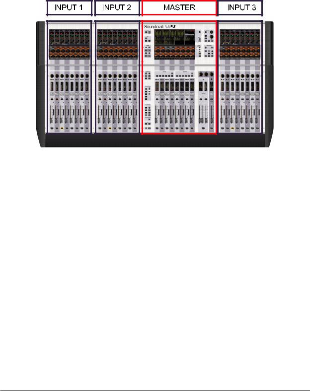
CONSOLE OVERVIEW
Bays
The Desk is based on 4 bays:
*3 INPUT bays
*1 MASTER bay
Figure 1-1. Console Bays.
*Each Input bay contains 8 complete Fader strips with full state overview, giving in total 24 directly accessible Input Strips.
*The Master bay contains 8 Output Fader strips, the 3 Masters and 16 Output encoders that give a total of 27 Output levels that can be directly controlled without changing Layers. General Functions like Snapshot, Monitoring, TB & OSC and so on are also located on the Master bay.
Page 1 - 8 |
Soundcraft Vi4™ User Guide |
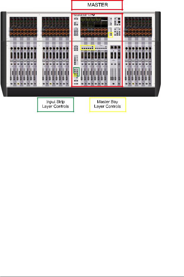
Layers
Figure 1-2. Layer Controls.
The console is able to control 48 inputs and 27 mix busses via its 24 input strips, 8 bus master strips and the LCR masters. To do this the console has a number of layers which the user accesses via the layer controls shown above.
Full details are given in chapter 8 of this manual.
Soundcraft Vi4™ User Guide |
Page 1 - 9 |
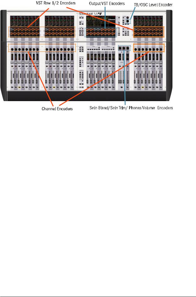
Encoders
Figure 1-3. Encoders.
*The 48 Vistonics™II row 1 and 2 encoders, including switches, are used in different modes, in which they can change in order to show various functions in a context-sensitive way.
*In normal operation they act as Input channel related controls.
*The 24 Channel encoders are assigned with Input channel related functions.
*The 16 Vistonics™ II output encoders are normally used as Output faders and are also context sensitive.
*There are four panel-mounted encoders with LED rings: the TB/OSC Level Control encoder, and the Sold Blend, Solo Trim & Phones Volume encoders. These are dedicated to their respective functions.
A detailed explanation of encoder use is given in chapter 7 of this manual.
Page 1 - 10 |
Soundcraft Vi4™ User Guide |
Master Audio Functions
Figure 1-4. Master Audio Functions.
*The Monitoring system contains the functionality to listen to and monitor the audio signal at several points in the console.
*TB/OSC system contains the Talkback functionality and the oscillator settings.
*The Meter panel provides a full overview of all 48 Input and 27 Output levels.
Soundcraft Vi4™ User Guide |
Page 1 - 11 |
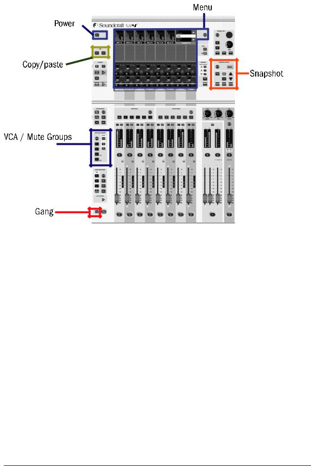
Master Control
Figure 1-5. Master Control.
*VCA/Mute Groups: this functional block contains the VCA (control groups in VCA style) and Mute Group functions.
*Snapshot allows the console’s automated settings to be saved and recalled.
*Menu opens the Menu page where central configurations can be done.
*Copy / paste functionality can be used in different modes and speeds up repetative tasks..
*Gang is a superb feature that links channels functions together for temporary changes.
*[Power] switches the Desk on and off, while [MUTE ALL] Outputs is helpful in emergency situations.
Page 1 - 12 |
Soundcraft Vi4™ User Guide |

SYSTEM COMPONENTS
Soundcraft Vi4™ User Guide |
Page 2 - 1 |
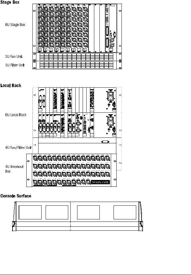
SYSTEM HARDWARE OVERVIEW
Figure 2-1. The System’s Three Component Parts.
Page 2 - 2 |
Soundcraft Vi4™ User Guide |
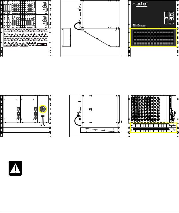
NOTE ON INSTALLATION OF THE COOLING FANS/FILTERS
The Stage Box and Local Rack may be ordered already fitted into flight cases, in which case the cooling fans/filters will already be located correctly as shown in the diagrams below.
If the system has been ordered without flightcases, in order that it can be permanently installed, please ensure that the cooling fans/filters are located as shown below.
Local Rack
Figure 2-2a: Layout Of Local Rack.
Stage Box
Figure 2-2b: Layout Of Stage Box.
NOTE: Ensure fan units on Local Rack and Stagebox are connected and operational.
CLEAN FILTERS REGULARLY!
The filters are outlined in yellow in the figures above.
Soundcraft Vi4™ User Guide |
Page 2 - 3 |
THE CONSOLE REAR CONNECTORS
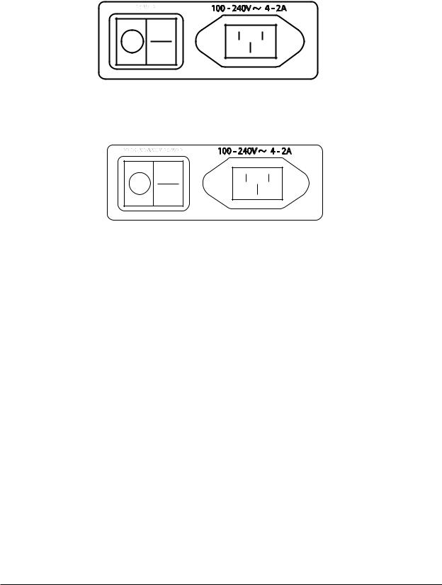
Mains Power Supply Inlet
The mains input is via an IEC connector, with an associated switch, as shown below. This feeds power to the primary PSU.
Figure 2-3a: Main Primary Supply Inlet.
An optional redundant primary supply may also be fitted. Its inlet connector is as shown below.
Figure 2-3b: Redundant Primary Supply Inlet.
Audio And Data Rearcon
MIDI Connectors
These are provided by the usual 5-pin DIN connectors.
HiQNet™ Connector
This is an XLR-housed EtherCon connector.
USB Connectors
Use one of these to connect a PC-type keyboard. There is another USB connector on the front panel. A memory stick can be used with either of these two free connectors.
Talkback Mic
This connector is a parallel connection to the front-panel talkback mic connector, and has an associated 48V switch for use if the microphone used requires phantom power.
TB Link, Phones L & R and Control Data
This group of four sockets (3 XLRs and an XLR-housed EtherCon connector) are used to link the console’s control surface to the Local Rack. The cable to do this (part number RL0267-01) is supplied with the system. The function of each of the connectors in this cable is marked with a cable sleeve.
Page 2 - 4 |
Soundcraft Vi4™ User Guide |
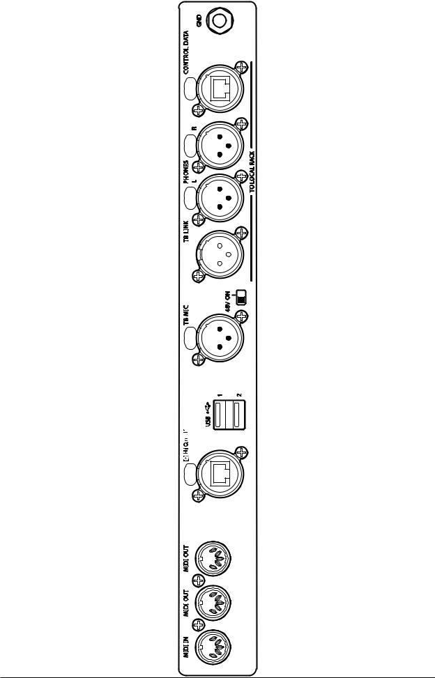
Figure 2-4: Console Rearcon Panel.
Soundcraft Vi4™ User Guide |
Page 2 - 5 |
LOCAL RACK
Local Rack Description
The Local Rack is the audio ‘brain’ of the Soundcraft Vi4™, it contains the DSP mixing processor and the local I/O connections.
The rack consists of a 6U processing and I/O unit, developed by Studer, called the S-Core. Below this is a 4U low-noise cooling fan unit. The S-Core itself consists of two sections: the upper 3U section houses the DSP mixing core, and the lower 3U section houses the local audio I/O and also the connections to the remote Stage Box.
The audio processing inside the S-Core is independent of the control surface. This means that the audio will continue to pass even if the control surface is switched off or disconnected from the core.
How It Works
The control surface sends control data to the Bridge Card, which is a communication and processing hub situated in the centre of the top 3U section of the Local Rack. The Bridge Card interprets the control data and sends internal data to the two DSP Pro cards and the FX Card (when fitted). These cards actually process the audio. The audio input and output connections to the DSP cards are made via 4 short CAT 5 patch cables, which connect the DSP cards with the I/O rack in the lower 3U section of the core.
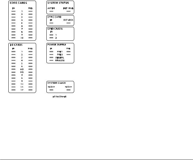
Front Panel
The front panel contains the Status LED array.
Figure 2-5: Status LEDs.
These LEDs give an at-a-glance indication that the Local Rack is functioning correctly, or that an error condition has occured. An illuminated green LED indicates the presence of a card, an illuminated red LED warns of a card error.
Note that there is a RECONFIG button behind a small hole at the bottom right of the panel. When pressed with a small screwdriver or similar a reset is applied to the lower row of cards in the local rack: this will force a re-polling of the loaded cards to reconfigure the console. This needs to be done only if the card configuration has been changed.
Page 2 - 6 |
Soundcraft Vi4™ User Guide |

Local Rack Rear
The rear of the Local Rack gives access to the cards in the card frame, and to the XLR breakout box.
Primary Power Supply
The primary power supply connects directly to the IEC inlet and provides a full range ac inlet, converting 100V to 240V ac to 24V dc. The Local Rack can hold up to two power supplies, providing seamless redundancy for those that require it. The rack fan control connection is also provided by one of the power supplies.
XLR Breakout Box
This provides connectors for analogue and AES/EBU audio, and interfaces to the Line In cards, Line Out cards, Mic card and AES/EBU Card within the Local Rack card frame. All the connectors on the Breakout Box are of the XLR type.
It is possible to order the console without this part, in this case the user will have to provide suitable cabling and connectors to interface with the appropriate Local Rack cards. A complete pin list is given later in this chapter.
The Breakout Box connector labelling references are used by the patching system (see chapter 11) when the user wishes to patch the connectors to input channels or output busses.
Audio I/O Cards
The following cards are supported.
1 X Mic/Line Input card providing four electronically balanced Mic/Line Input channels, each with digitally-controlled analogue gain, a 80Hz low-cut filter, and phantom power.
2 X Line Input cards, each providing eight line input channels.
3 X Line Output cards, each providing eight line output channels.
1 X AES I/O card, providing 16 AES input channels and 16 AES output channels.
1 X MADI Stage Box interface card ( normally Cat 5, but it can optionally be replaced by an optical MADI card).
1 X Optical MADI card, providing 64 MADI input and 64 MADI output channels. See page 2-10 for more details.
Soundcraft Vi4™ User Guide |
Page 2 - 7 |

Local Rack Rear View
The rear view is shown below. Note that the last remaining connector from the console surface (the RJ45 ethernet connector) goes into the top socket on the bridge card.
Figure 2-6: Local Rack Rear View.
Page 2 - 8 |
Soundcraft Vi4™ User Guide |
 Loading...