


SOUNDCRAFT RM100
USER GUIDE

ã Harman International Industries Ltd. 1994, 1997 All rights reserved
Parts of the design of this product may be protected by worldwide patents.
Part No. ZM0079 Issue 3
Soundcraft is a trading division of Harman International Industries Ltd.
Information in this manual is subject to change without notice and does not represent a commitment on the part of the vendor. Soundcraft shall not be liable for any loss or damage whatsoever arising from the use of information or any error contained in this manual, or through any mis-operation or fault in hardware contained in the product.
No part of this manual may be reproduced, stored in a retrieval system, or transmitted, in any form or by any means, electronic, electrical, mechanical, optical, chemical, including photocopying and recording, for any purpose without the express written permission of Soundcraft.
It is recommended that all maintenance and service on the product should be carried out by Soundcraft or its authorised agents. Soundcraft cannot accept any liability whatsoever for any loss or damage caused by service, maintenance or repair by unauthorised personnel.
Harman International Industries Ltd.
Cranborne House
Cranborne Industrial Estate
Cranborne Road
Potters Bar
Herts.
EN6 3JN
England
Tel: 0707 665000
Fax: 0707 660482

&RQWHQWV
Introduction |
1.1 |
Introduction |
1.2 |
Precautions and Safety Instructions |
1.4 |
Installation |
2.1 |
Installation |
2.2 |
Connections |
2.3 |
Module Block Diagrams |
3.1 |
Mic/Line Input Module |
4.1 |
Description & Operation |
4.2 |
Specifications |
4.4 |
Stereo Input Module |
4.5 |
Description & Operation |
4.6 |
Specifications |
4.8 |
Telco Input Module |
4.9 |
Description & Operation |
4.10 |
Specifications |
4.12 |
Master Module |
4.13 |
Description & Operation |
4.14 |
Specification |
4.18 |
Meterbridge |
4.19 |
Stereo Source Select Module |
4.20 |
Appendices |
A.1 |
Dimensions |
A.2 |
Glossary |
A.3 |
Warranty |
A.4 |
CPS150 Power Supply |
P.1 |

Introduction
Introduction
Precautions and Safety Instructions
Introduction |
1.1 |

,QWURGXFWLRQ
The RM100 is designed as a simple-to-operate on-air Radio console. Front panel controls are kept to a minimum to give a clear and uncluttered appearance while providing sufficient flexibility and choice to meet individual requirements.
The design of the console allows for desktop mounting or drop-through mounting into a table-top.
A choice of input modules and frame sizes is available, with the option of a script tray on the larger frame sizes.
The console features illuminated switches throughout for clear operation and a choice of high quality carbon or conductive plastic faders.
Frame Sizes
The RM100 is available in three frames sizes:
∙8 Inputs + Master
∙12 Inputs + Master
∙20 Inputs + Master
Module Options
Frames may be fitted with a choice of modules as follows:
∙Mono Mic/Line Input module
∙Stereo Line Input module
∙Telco Input module
∙Master Broadcast Module
∙Master Production Module (with PGM and AUD Master Faders)
Metering |
Two meterbridge styles are available. |
|
|
The standard version comprises: |
|
|
∙ |
a single pair of VU meters (PPM meters optional) |
|
∙ |
two pairs of VU meters on the 20 input frame |
The alternative version comprises:
∙a single pair of VU meters (PPM meters optional)
∙two pairs of VU meters on the 20 input frame
∙4-digit timer module
∙cue loudspeaker
1.2 |
Introduction |

Power Supplies
∙ 8, 12 and 20 input frames CPS150 power supply
Introduction |
1.3 |

3UHFDXWLRQV DQG 6DIHW\ ,QVWUXFWLRQV
General Precautions
Avoid storing or using the mixing console in conditions of excessive heat or cold, or in positions where it is likely to be subject to vibration, dust or moisture. Do not use any liquids to clean the fascia of the unit: a soft dry brush is ideal. Use only water or ethyl alcohol to clean the trim and scribble strips. Other solvents may cause damage to paint or plastic parts.
Avoid using the console close to strong sources of electromagnetic radiation (e.g. video monitors, highpower electric cabling): this may cause degradation of the audio quality due to induced voltages in connecting leads and chassis. For the same reason, always site the power supply away from the unit.
Caution! In all cases, refer servicing to qualified personnel.
Handling and Transport The console is supplied in a strong carton. If it is necessary to move it any distance after installation it is recommended that this packing is used to protect it. Be sure to disconnect all cabling before moving. If the console is to be regularly moved we recommend that it is installed in a foamlined flightcase. At all times avoid applying excessive force to any knobs, switches or connectors.
Power Supplies & cables Always make sure that the power supply unit (PSU) has been set to the same voltage as the mains supply
Always use the power supply and cable supplied with the mixer: the use of alternative supplies may cause damage and voids the warranty; the extension of power cables may result in malfunction of the mixing console.
Warning! Always switch the power supply off before connecting or disconnecting the mixer power cable, removing of installing modules, and servicing. In the event of an electrical storm, or large mains voltage fluctuations, immediately switch off the PSU and unplug from the mains.
Always ensure that you use the correct PSU for your mixer. The RM100 uses a
CPS150 power supply for the 8, 12 and 20 input frames.
1.4 |
Introduction |

Signal Levels
It is important to supply the correct input levels to the console, otherwise signalto noise ratio or distortion performance may be degraded; and in extreme cases, damage to the internal circuitry may result. Likewise, on all balanced inputs avoid sources with large commonmode DC, AC or RF voltages, as these will reduce the available signal range on the inputs. Note that 0dBu = 0.775V RMS.
The microphone inputs are designed for use with balanced low impedance (150 or 200 ohms) microphones.
Caution! DO NOT use unbalanced microphones or battery powered condenser microphones without isolating the +48V phantom power: degraded performance or damage to the microphone may result.
The sensitivity of the Mic inputs is variable from -20dBu to -70dBu, with a maximum input level of +6dBu. The Line Input sensitivity is variable from -48dBu to +2dBu with a maximum input level of +28dBu.
The Stereo and Telco input sensitivity is variable from -12dBu to +9dBu, with a maximum input level of +28dBu.
The main outputs of the console (PGM, AUD and MONO) are balanced at a nominal level of 0dBu, with the option of -10dBV on the AUD output by changing internal jumpers. Maximum output level is +26dBu into 600 ohms.
The Telco mix-minus output is balanced at a nominal level of 0dBu with a maximum output level of +20dBu into 600 ohms.
Introduction |
1.5 |

1.6 |
Introduction |
Installation
Installation |
2.1 |

,QVWDOODWLRQ
The RM100 is designed for reliability and high performance, and is built to the highest standards. Whilst great care has been taken to ensure that installations are made as troublefree as possible, care taken at this stage, followed by correct setting up will be rewarded by a long life and reliable operation.
Wiring Considerations |
A |
For optimum performance it is essential for the earthing system to be clean and |
|
noisefree, as all signals are referenced to this earth. A central point should be |
|
|
decided on for the main earth point, and all earths should be ’star-fed’ from this |
|
|
point. It is recommended that an individual earth wire be run from each electrical |
|
|
outlet, back to the system star point to provide a safety earth reference for each piece |
|
|
of equipment. |
|
|
B |
Install separate mains outlets for the audio equipment, and feed these |
|
independently from any other equipment. |
|
|
C Avoid locating mains distribution boxes near audio equipment, especially tape |
|
|
recorders, which are very sensitive to electromagnetic fields. |
|
|
D |
Where possible ensure that all audio cable screens and signal earths are |
connected to ground only at their source.
Power Supply
Warning!
Always ensure that you use the correct PSU for your mixer. The RM100 uses a CPS150 power supply for the 8, 12 and 20 input frames.
Before switching on your RM100 console, check that the mains voltage selectors on the power supply unit is set to the correct mains voltage for your area, and that the fuse is of the correct rating and type. This is clearly marked on the case of the power supply. Do not replace the fuse with any other type, as this could become a safety hazard and will void the warranty.
2.2 |
Installation |
&RQQHFWLRQV
Wiring conventions
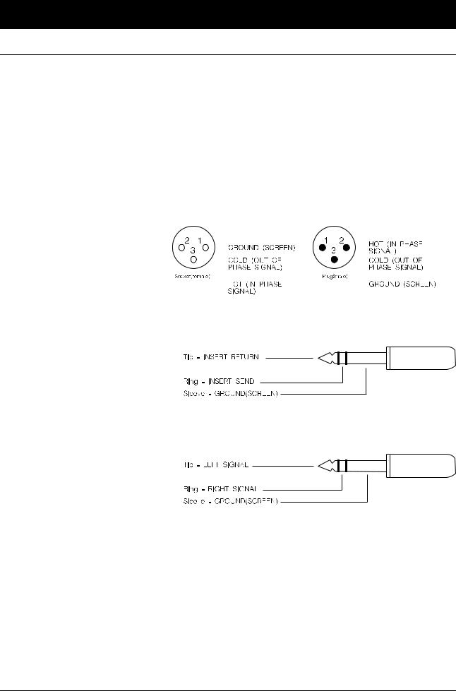
The RM100 uses various different types of audio connector: 3-pin XLR , 1¤4" 3-pole jacks and ‘D’ type connectors. This section describes how to connect external equipment to the console. Correctly-made cables of the proper type will ensure peak performance from your console.
MICROPHONE INPUTS |
PGM, AUD, MONO |
|||||||||||||||||||
|
& LINE INPUTS |
& C/F OUTPUTS |
||||||||||||||||||
|
|
|
|
|
|
|
|
|
|
|
|
|
|
|
|
|
|
|
|
|
|
|
|
|
|
|
|
|
|
|
|
|
|
|
|
|
|
|
|
|
|
|
|
|
|
|
|
|
|
|
|
|
|
|
|
|
|
|
|
|
|
|
|
|
|
|
|
|
|
|
|
|
|
|
|
|
|
|
|
|
|
|
|
|
|
|
|
|
|
|
|
|
|
|
|
|
|
|
|
|
|
|
|
|
|
|
|
|
|
|
|
|
|
|
|
|
|
|
|
|
|
|
|
|
|
|
|
|
|
|
|
|
|
|
|
|
|
|
|
|
|
|
|
|
|
|
|
|
|
|
|
|
|
|
|
|
|
|
|
|
|
|
|
|
|
|
|
|
|
|
|
|
|
|
|
|
|
|
|
|
|
|
|
|
|
|
|
|
|
|
|
|
|
|
|
|
|
|
|
|
|
|
|
|
|
|
|
|
|
|
|
|
|
|
|
|
|
|
|
|
|
|
|
|
|
|
|
|
|
|
1/4" `A' Gauge Stereo Jack Plug used as an insert point:
1/4" `A' Gauge Stereo Jack Plug used as stereo output: Headphones and Control Room Monitors
The following pages give details of the connectors which are not covered by the diagram above.
Installation |
2.3 |

Stereo Input Module
Input 2 + Remotes (15-pin ‘D’ type connector)
Pin 1 |
Chassis |
Pins 2, 9 |
Machine 1 Start |
Pins 3, 10 |
Machine 1 Stop |
Pins 4, 11 |
Machine 2 Start |
Pins 5, 12 |
Machine 2 Stop |
Pins 6, 13 |
Input 2 Right -,+ |
Pin 7 |
Ground |
Pins 8, 15 |
Input 2 Left -,+ |
Pin 14 |
Ground |
Telco Input Module
Remotes (15-pin ‘D’ type connector)
Pin 1 |
Chassis |
Pin 2 |
Divert n/c |
Pin 3 |
Divert n/o |
Pins 9,10 |
Divert common |
Pin 8 |
Insert Return |
Pin 15 |
Insert Send |
Pins 7, 14 |
Ground |
Pins 4, 5, 6, 11, 12, 13 |
no connection |
Master Module
External Inputs (15-pin ‘D’ type male connector)
Pin 1 |
Chassis |
Pin 2 |
External Input 1 Left + |
Pin 3 |
External Input 1 Right + |
Pin 4 |
External Input 2 Left + |
Pin 5 |
External Input 2 Right + |
Pin 6 |
Ground |
Pin 7 |
External Input 3 Left |
Pin 8 |
External Input 3 Right |
Pin 9 |
External Input 1 Left - |
Pin 10 |
External Input 1 Right - |
Pin 11 |
External Input 2 Left - |
Pin 12 |
External Input 2 Right - |
Pin 13 |
Ground |
Pin 14 |
External Input 4 Left |
Pin 15 |
External Input 4 Right |
2.4 |
Installation |

Master Module
Remote (9-pin ‘D’ type connector)
Pin 1 |
C/Room Mute Contact 1 common |
Pin 2 |
C/Room Mute Contact 1 n/o |
Pin 3 |
C/Room Mute Contact 2 common |
Pin 4 |
C/Room Mute Contact 2 n/o |
Pin 5 |
no connection |
Pin 6 |
no connection |
Pin 7 |
no connection |
Pin 8 |
no connection |
Pin 9 |
no connection |
Guest H/P + Rev T/B (9-pin ‘D’ type connector)
Pin 1 |
Chassis Ground |
Pin 2 |
Guest Headphones Left Ground |
Pin 3 |
Guest Headphones Left Signal |
Pin 4 |
Guest Headphones Right Ground |
Pin 5 |
Guest Headphones Right Signal |
Pin 6 |
Audio Ground |
Pin 7 |
Reverse Talkback Input |
Pin 8 |
Reverse Talkback Control Signal |
Pin 9 |
no connection |
Installation |
2.5 |

2.6 |
Installation |

Module Block Diagrams
Module Block Diagrams |
3.1 |

3.2 |
Module Block Diagrams |

Mic/Line Input Module
Description & Operation
Specification
Mic/Line Input Module |
4.1 |
 Loading...