


Thank you for purchasing a SPIRIT LIVE 32 mixer, brought to you with pride by the SPIRIT team of Graham, Simon, James, Chris, Colin, Andy, Peter, Martin, René, Roland and Kevin, with the support of many others - we hope you will have as much fun using it!
© Spirit By Soundcraft™ 1995 All rights reserved
Parts of the design of this product may be protected by worldwide patents
Issue 1
Part No. ZM0???
Information in this manual is subject to change without notice and does not represent a commitment on the part of the vendor. Spirit By Soundcraft™ shall not be liable for any loss or damage whatsoever arising from the use of information or any error contained
in this manual.
No part of this manual may be reproduced, stored in a retrieval system, or transmitted, in any form or by any means, electronic, electrical, mechanical, optical, chemical, including photocopying and recording, for any purpose without the express written permission of Spirit By Soundcraft™.
It is recommended that all maintenance and service on the product should be carried out by Spirit By Soundcraft™ or its authorised agents. Spirit By Soundcraft™ cannot accept any liability whatsoever for any loss or damage caused by service, maintenance or repair by unauthorised personnel.
Spirit By Soundcraft™.
Harman International Industries Ltd.,
Cranborne House,
Cranborne Industrial Estate,
Cranborne Road,
Potters Bar,
Hertfordshire,
EN6 3JN, U.K.
Tel: |
+44 (0) 1707 665000 |
Fax: |
+44 (0) 1707 660461 |

INTRODUCTION
Thanks for purchasing a SPIRIT LIVE 32 mixer. Owning a Soundcraft console brings you the expertise and support of one of the industry’s leading manufacturers and the results of over 22 years experience supporting some of the biggest names in the busi-
ness.
Designed by engineers who understand the individual needs of musicians, SPIRIT LIVE 32 has been built to the highest standards using quality components and employing automated assembly techniques beyond the reach of most manufacturers of compact mixers.
A rugged steel chassis is combined with moulded side trims to give protection and a distinctive appearance. Custom moulded controls, designed for the best `feel’ and visual clarity, complement the styling, resulting in a truly professional product which is ideal for both touring and fixed PA installations.
SPIRIT LIVE 32 is available in 8, 12, 16 and 24 channel frame sizes, which may be extended by adding an 8 channel Expander. The Expander can be attached quickly and securely to the console, requiring only a screwdriver and a steady hand to complete the installation.
SPIRIT LIVE 32 incorporates circuit technology identical to that used on some of the most sophisticated Soundcraft consoles. The input channels are able to accept a wide range of Microphone and Line level signals from separate input sockets. Every channel features wide-range gain control, 4-band Equalisation with swept Hi and Lo Mid ranges, plus a Hi-Pass Filter, 4 Auxiliary Sends, PFL(Pre Fade Listen), Peak LED, Panning to a Stereo bus and routing to a separate Mono bus. The additional bus is a unique feature at this price level and is ideal for driving a centre loudspeaker cluster, or with the Left and Right busses used as subgroups and mixed down to the Mono bus, as the main output. Each channel is controlled by a high-quality long throw fader.
All frame sizes are provided as standard with two dedicated stereo inputs. Each stereo input comprises switchable input gain, two-band EQ and sends to Aux 1 & 2, Mix and Mono busses.
The Master section provides master level control for the Left, Right, Mono and Auxiliary Send buses, with separate AFL monitoring on each Auxiliary Send. Aux 2 & 3 may both be selected as PRE or POST fade sends, allowing flexibility for foldback or effects.
Two Stereo Effects Returns are provided, with switchable input gain and mixing to Left and Right busses.
A dedicated stereo output is provided for recording the Mix. By selecting internal links the Mono output can also be recorded via this stereo output.
The Mix L/R and Mono outputs all have insert points for the connection of external signal processors. Two 12-segment, 3-colour peak-reading LED bargraph meters display the selected headphones source, allowing monitoring of Mix or Mono signals. Pressing any PFL or AFL switch puts the selected signal onto both sides of the headphones output, and the L & R bargraph meters in place of the selected signal.
SPIRIT Live 32 is designed to be as user-friendly as possible, but a few minutes spent reading through this manual will help you become familiar with the product away from the pressure of a live session, and allow you to gain full benefit from the superb performance offered by your new mixer.
Above all, remember that your SPIRIT mixer is designed to extend your creativity. The more you explore the controls and the effect they have on the sound output, the more you will appreciate how you can influence and enhance the final sound.
Page 1

BASIC PRINCIPLES OF PA MIXING
There was a time when the P.A. system and the operator existed only to increase the overall volume of the performers, so that they could be heard in a large room or above high ambient noise levels. This just isn’t true any more. The sound system and the sound engineer have become an integral part of the performance, and the artists are
heavily dependent on the operator’s skill and the quality of the equipment.
The following introduction to the basics of mixing are included for the benefit of those users who may not have any significant familiarity with sound equipment, and who are baffled by the endless jargon used by engineers and artists alike.
The Mixer
As one would expect, the main purpose of the mixer is to combine sounds, but under precise and smooth control. This is why long-throw faders are essential on any professional product. The faders provide you with clear and instinctive control of the final sound balance and like an artist playing an instrument you should listen to the effect of your fader movements, not look at your hands.
Your SPIRIT LIVE 32 mixer accepts a wide range of input signals via the UltraMic Plus™ microphone input (for very low level signals) or a line input (for higher level signals) from, for instance, tape machines, effects processors, etc.
Note: Mic and Line inputs have the same gain range, differing only in source impedance.
The mixer is split into two sections. The Inputs receive, match and process individual source signals, and distribute them at precise mix levels to either a stereo Mix output or Mono output. The Master section allows overall level control of all outputs, and provides monitoring of the audio signal at many points in the mixer, either on headphones or meters.
The Equaliser controls are the most flexible and potentially destructive feature of the mixer. They have a similar effect on the frequency response of the input channel as the tone controls on a hi-fi system, but with much greater precision, and allow particular characteristics of the input signal to be emphasised or reduced. It is very important that you become familiar with the effect each control has on the sound and this is best achieved by spending time listening to the effect of each control on a well-known track played through the mixer.
The Auxiliary Sends provide a way of routing the input signals to a number of secondary outputs, for artists foldback, FX units or additional speaker outputs.
The Pan control adjusts the position of the input signal within the stereo mix, and can be swept from full left, through to full right. This allows particular artists to retain their correct spatial position within the mix, and can be valuable for live effects.
Pre-Fade-Listen(PFL) allows you to monitor the signal at many points in the mixer. Pressing any PFL switch routes the signal at that particular point into the headphones and the meters, to check the quality of the signal or to pin-point problems. Using PFL will not affect the signals on the outputs from the desk.
Each input channel and the three main outputs have an Insert `A’ gauge jack socket, which is a break point in the signal path. It allows the signal to be taken out of the mixer, through an external piece of equipment and then back into the mixer directly after its original exit point. The Insert point is normally bypassed by the `A’ gauge jack socket contacts, and is only brought into operation when a plug is inserted. Typical uses would include Effects Processing, Limiting, additional Equalisation or Delay.
Page 2
The terms PRE and POST are often used in the context of Inserts, Equalisers and Auxiliary Sends, and describe whether that facility is placed before (Pre) or after (Post) another particular section. This is explained further in the detailed description of facilities.
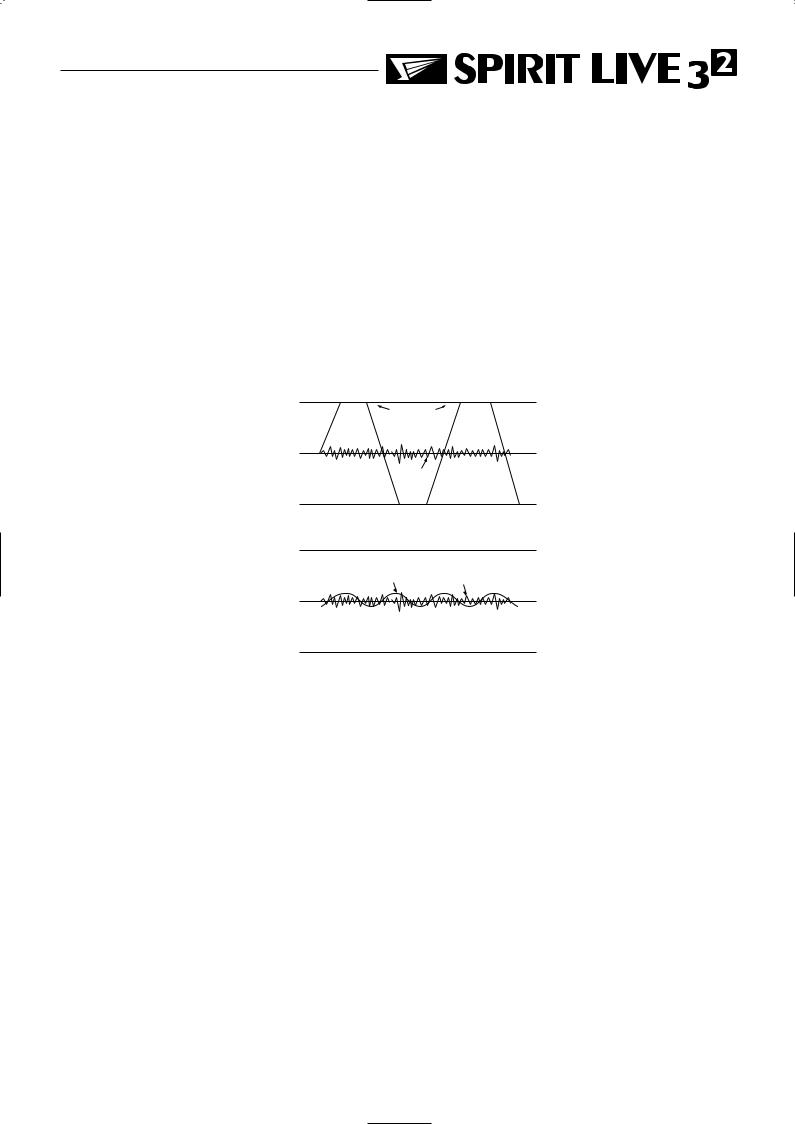
A mixer is often judged, amongst other factors, by the amount of Headroom available. This is a measure of the reserve available to cope with sudden peaks in the input signal, without distortion caused by Clipping, when the signal becomes so high that it would exceed the power supply rail voltages and is as a result limited. This commonly occurs where gain settings are incorrectly set or where sources are improperly matched to the mixer input. If the source signal is too high, clipping and distortion results. If the signal is too low it becomes masked by the background noise which is present to some degree in all mixers, although minimal in SPIRIT products. The diagram below illustrates this point.
Clipped
Signal
Noise
If the signal level is too high, clipping distortion may occur.
Signal Noise
If the signal level is too low it may be masked by the noise.
Page 3

Installation and Safety Precautions
Installing the Mixer
Correct connection and positioning of your mixer is important for successful and troublefree operation. The following sections are intended to give guidance with cabling, connec-
tions and configuration of your mixer.
oChoose the mains supply for the sound system with care, and do not share sockets or earthing with lighting dimmers.
oPosition the mixer where the sound can be heard clearly, preferably in the centre, and within the audience.
oRun audio cables separately from lighting circuits, using balanced lines wherever possible. If necessary, cross audio and lighting cables at right angles to minimise the possibility of interference. Keep unbalanced cabling as short as possible.
oDo not mix phases on a 3-phase supply without consulting an electrician.
oCheck your cables regularly and label each end for easy identification.
SAFETY PRECAUTIONS
For your own safety, and to avoid invalidation of the warranty, please read this section carefully.
The LIVE 32 mixer must only be connected through the Power Supply supplied.
The wires in the mains lead are coloured in accordance with the following code:
Earth: |
Green and Yellow |
(Green/Yellow - US) |
Neutral: |
Blue |
(White - US) |
Live: |
Brown |
(Black - US) |
As the colours of the wires in the mains lead may not correspond with the coloured markings identifying the terminals in your plug, proceed as follows:
The wire which is coloured Green and Yellow must be connected to the terminal in the plug which is marked with the letter E or by the earth symbol.
The wire which is coloured Blue must be connected to the terminal in the plug which is marked with the letter N.
The wire which is coloured Brown must be connected to the terminal in the plug which is marked with the letter L.
Ensure that these colour codings are followed carefully in the event of the plug being changed.
To avoid the risk of fire, replace the mains fuse only with the correct value fuse, as indicated on the power supply.
Page 4
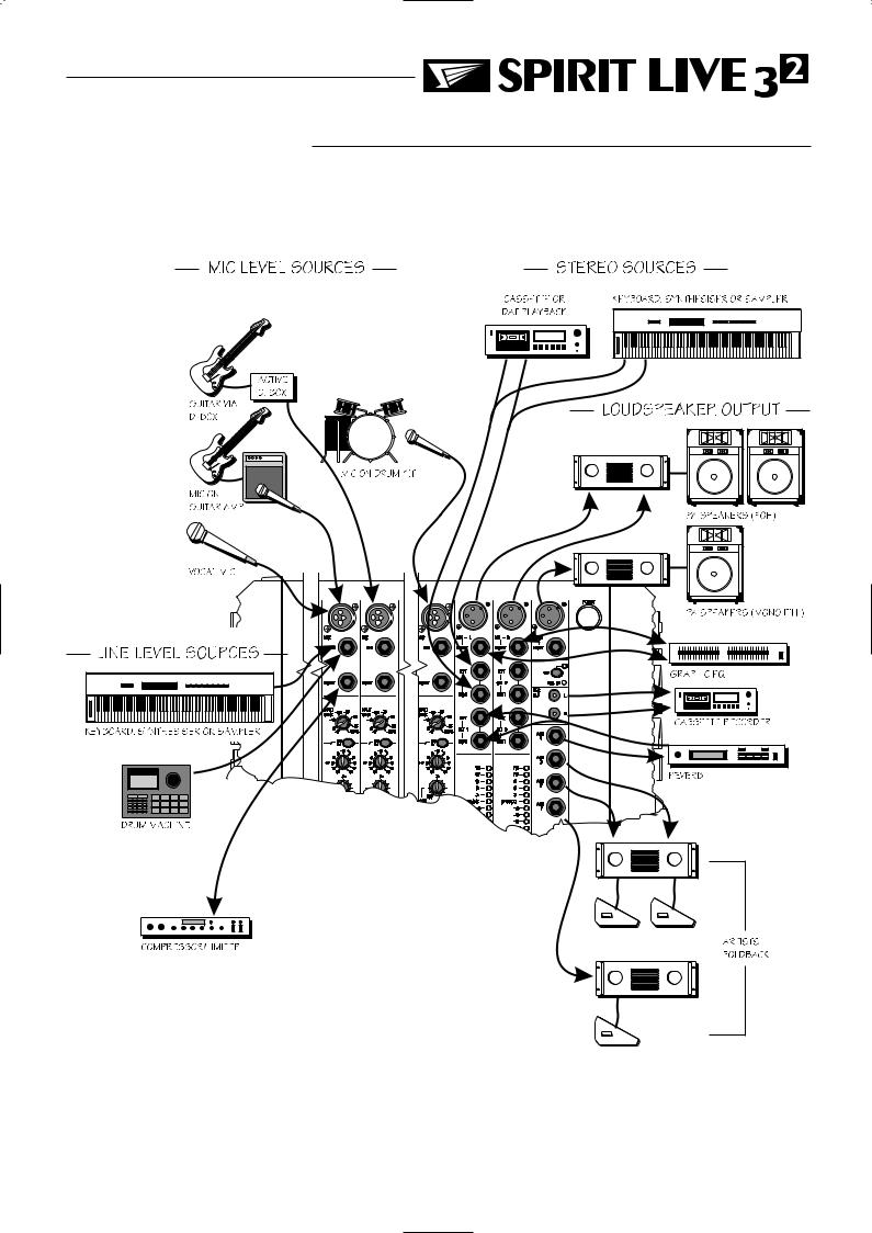
CONNECTING IT UP
The diagram below shows various equipment that would be connected to a SPIRIT Live 32
Page 5
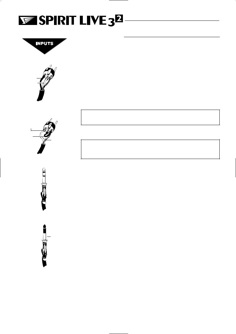
Balanced Mic
XLR
2. Hot(+ve)
3. Cold(-ve)

 1. Screen
Unbalanced Mic
XLR
2. Hot(+ve)
Link |
3 |
to |
1 |
|
1. Screen |
WIRING IT UP
MIC INPUT
The mic input accepts XLR-type connectors and is designed to suit a wide range of BALANCED or UNBALANCED low-level signals, whether from delicate vocals requiring the best low-noise performance or close-miked drum kits needing maximum headroom. Professional dynamic, condenser or ribbon mics are best because these will be LOW IMPEDANCE. While you can use low-cost HIGH IMPEDANCE mics, you do not get the same degree of immunity to interference on the microphone cable and as a result the level of background noise may be higher. If you turn the PHANTOM POWER on, the socket provides a suitable powering voltage for professional
condenser mics.
DO NOT use unbalanced sources with the phantom power switched on. The voltage on pins 2 & 3 of the XLR connector may cause serious damage.
The input level is set using the INPUT knob.
WARNING - Start with the INPUT knob at the ‘-6’ position when plugging high level sources into the LINE input to avoid overloading the input channel or giving you a very loud surprise!
Balanced |
|
|
|
|
Unbalanced |
||||
3 pole Jack |
|
|
|
|
3 pole Jack |
||||
Hot |
(+ve) |
|
|
|
|
|
|
|
Signal |
|
|
|
|
||||||
Cold |
(-ve) |
|
|
|
|
|
|
Gnd/Screen |
|
|
|
|
|
|
|
||||
Gnd/Screen |
|
|
|
|
|
Gnd/Screen |
|||
|
|
|
|
|
|||||
Tip 
Ring 

 Sleeve
Inserts

 Signal Send

 Signal Return
Gnd/Screen
Tip 
Ring 

 Sleeve
LINE INPUT
The LINE input offers the same gain range as the MIC input, but at a higher input impedance. This is suitable for most line level sources, and provides the gain needed for lower level keyboards and high impedance microphones. The input accepts 3-pole `A’ gauge jacks, or 2-pole mono jacks which will automatically ground the ‘cold’ input. Use this input for sources other than mics, such as keyboards, drum machines, synths, tape machines or guitars. The input is BALANCED for low noise and immunity from interference, but you can use UNBALANCED sources by wiring up the jacks as shown, although you should then keep cable lengths as short as possible to minimise interference pick-up on the cable. Refer to the section ‘How to Prevent Interference’ later in this manual. Note that the ring must be grounded if the source is unbalanced. Set the input level using the INPUT knob, starting with the knob turned fully anticlockwise. Plugging into the LINE input automatically cuts off the MIC input.
Note that with high level sources it may be necessary to reduce the level at source to avoid overloading the input.
INSERT POINT
The unbalanced, pre-EQ insert point is a break in the channel signal path, allowing limiters, compressors, special EQ or other signal processing units to be added in the signal path. The Insert is a 3-pole ‘A’ gauge jack socket which is normally bypassed. When a jack is inserted, the signal path is broken, just before the EQ section.
The signal from the channel appears on the TIP of the plug and is returned on the RING, with the sleeve as a common ground.
Page 6
Mix Outputs
Mono Output
1. Screen 


 3. Signal -
2. Signal +
Mix & Mono Inserts

 Signal Send

 Signal Return
Gnd/Screen
Tip 
Ring 

 Sleeve
STEREO INPUTs, STEREO RETURNS
Accept 3-pole `A’ gauge jacks, or 2-pole mono jacks which will automatically ground the ‘cold’ input. Use these inputs for sources such as keyboards, drum machines, synths, tape machines or as returns from processing units. The input is BALANCED for low noise and immunity from interference, but you can use UNBALANCED sources by wiring up the jacks as shown, although you should then keep cable lengths as short as possible to minimise interference pick-up on the cable. Note that the ring must be grounded if the source is unbalanced. Mono sources can be fed to both paths by plugging into the Left jack only.
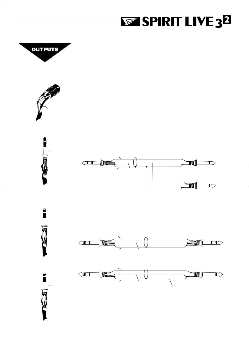
Mix INSERTS, MONO INSERT
The unbalanced, pre-fade insert points are a break in the output signal path to allow the connection of, for example, a compressor/limiter or graphic equaliser. The Insert is a 3-pole ‘A’ gauge jack socket which is normally bypassed. When a jack is inserted, the signal path is broken, just before the mix fader.
The mix signal appears on the TIP of the plug and is returned on the RING. A ‘Y’ lead may be required to connect to equipment with separate send and return jacks as shown below:
Signal Send (Tip) |
Send to External Device |
||
Insert Point |
Tip |
||
|
|||
|
|
||
|
Sleeve |
|
|
Screen |
Signal Return (Ring) |
|
|
(Sleeve) |
|
|
|
Tip |
Return from External Device |
Sleeve |
|
Aux Outputs

 Signal +

 Signal -
Screen
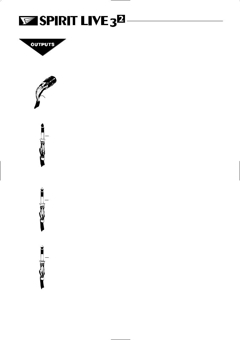
MIX & MONO OUTPUTS
The Mix and Mono outputs are on 3-pole XLR sockets, wired as shown on the left and below, and incorporate impedance balancing, allowing long cable runs to balanced amplifiers and other equipment.
From LIVE 32 |
Signal |
(a) Balanced Connection |
Impedance Balanced |
To External Device |
|
Output |
|
|
|
|
|
|
Screen |
Signal Ground |
Headphones

 Left Signal

 Right Signal
Ground
From LIVE 32
Impedance Balanced Signal
Output
Screen
(b) Unbalanced Connection
To External Device
Signal Ground
Experience has shown that sometimes it is better not to connect screen at external device end.
Page 7
Mix Outputs
Mono Output
1. Screen 


 3. Signal -
2. Signal +
Mix & Mono Inserts

 Signal Send

 Signal Return
Gnd/Screen
Tip 
Ring 

 Sleeve
Aux Outputs

 Signal +

 Signal -
Screen
Headphones

 Left Signal

 Right Signal
Ground
AUX OUTPUTS
The Aux outputs are on 3-pole ‘A’ gauge jack sockets, wired as shown on the left, and incorporate impedance balancing, allowing long cable runs to balanced amplifiers and other equipment.
HEADPHONES
The PHONES output is a 3-pole ‘A’ gauge jack, wired as a stereo output as shown, suitable for headphones of 200W or greater. 8W headphones are not recommended.
Polarity
You will probably be familiar with the concept of polarity in electrical signals and this is of particular importance to balanced audio signals. Just as a balanced signal is highly effective at cancelling out unwanted interference, so two microphones picking up the same signal can cancel out, or cause serious degradation of the signal if one of the cables has the +ve and -ve wires reversed. This phase reversal can be a real problem when microphones are close together and you should therefore take care always to connect pins correctly when wiring audio cables.
Grounding and Shielding
For optimum performance it is vital that all signals are referenced to a solid, noisefree earthing point and that all signal cables have their screens connected to ground. To avoid earth `loops’, use balanced connections where possible and ensure that all cable screens and other signal earths are connected to ground only at their source and not at both ends.
If the use of unbalanced connections is unavoidable, you can mimimise noise by following these wiring guidelines:
lOn INPUTS, unbalance at the source and use a twin, screened cable as though it were balanced.
lOn OUTPUTS, connect the signal to the +ve output pin, and the ground of the output device to -ve. If a twin screened cable is used, connect the screen only at the mixer end.
lAvoid running audio cables or placing audio equipment, close to thyristor dimmer units or power cables.
lNoise immunity is improved significantly by the use of low impedance sources, such as good quality professional microphones or the outputs from most modern audio equipment. Avoid cheaper high impedance microphones, which may suffer from interference over long cable runs, even with well-made cables.
Page 8
 Loading...