


PX40/PX35-VPL Projector Data LCD
4-090-532-13 (1)
Data Projector
Operating Instructions |
|
|
|
|
GB |
|
|
|
|
|
|
||
|
|
|
|
|
|
|
Mode d’emploi |
|
|
|
FR |
||
|
|
|
|
|
||
|
|
|
|
|
|
|
Manual de instrucciones |
|
ES |
||||
|
|
|
|
|||
VPL-PX40/PX35
© 2002 Sony Corporation

WARNING
To prevent fire or shock hazard, do not expose the unit to rain or moisture.
To avoid electrical shock, do not open the cabinet. Refer servicing to qualified personnel only.
This symbol is intended to alert the user to the presence of uninsulated “dangerous voltage” within the product’s enclosure that may be of sufficient magnitude to constitute a risk of electric shock to persons.
This symbol is intended to alert the user to the presence of important operating and maintenance (servicing) instructions in the literature accompanying the appliance.
GB 2
For the customers in the USA
This equipment has been tested and found to comply with the limits for a Class A digital device, pursuant to Part 15 of the FCC Rules. These limits are designed to provide reasonable protection against harmful interference when the equipment is operated in a commercial environment. This equipment generates, uses, and can radiate radio frequency energy and, if not installed and used in accordance with the instruction manual, may cause harmful interference to radio communications. Operation of this equipment in a residential area is likely to cause harmful interference in which case the user will be required to correct the interference at his own expense.
You are cautioned that any changes or modifications not expressly approved in this manual could void your authority to operate this equipment.
This label is located on
LASER RADIATION
DO NOT STARE INTO BEAM the rear of the Remote
CLASS 2 LASER PRODUCT
RAYONNEMENT LASER Commander.
NE PAS REGARDER DANS LE FAISCEA APPAREIL A LASER DE CLASSE 2
LASER–STRAHLING,
NICHT IN DEN STRAHL BLICKEN LASER KLASSE 2
MAX OUTPUT : 1mW |
EN60825- |
WAVE LENGTH : 645nm |
/A11:199 |
This label is located on the side of the Remote Commander.
CAUTION
LASER RADIATION
DO NOT STARE INTO BEAM
WAVE LENGTH:645nm
MAX OUTPUT:1mW
CLASS II LASER PRODUCT
COMPLIES WITH DHHS 21 CFR SUBCHAPTER J
SONY CORPORATION 6-7-35 KITASHINAGAWA
SHINAGAWA-KU,TOKYO,JAPAN
A
MANUFACTURED;
This label is located on the rear of the Remote Commander.
This label is located on
AVOID EXPOSURE- the rear of the Remote
LASER RADIATION IS
EMITTED FROM THIS Commander. APERTURE.
Laser light shines out of this window.
Caution
Use of controls or adjustments or performance of procedures other than those specified herein may result in hazardous radiation exposure.
Notes
•Do not aim the laser at people or not look into the laser transmitter.
•When the Remote Commander causes malfunction, consult with qualified Sony personnel. We change the Remote Commander as new one according to the guarantee.
For the customers in Canada
This Class A digital apparatus complies with Canadian ICES-003.
For the customers in the United Kingdom
WARNING
THIS APPARATUS MUST BE EARTHED
3 GB
IMPORTANT
The wires in this mains lead are coloured in accordance with the following code:
Green-and-Yellow:Earth Blue: Neutral Brown: Live
As the colours of the wires in the mains lead of this apparatus may not correspond with the coloured markings identifying the terminals in your plug proceed as follows: The wire which is coloured green-and- yellow must be connected to the terminal in the plug which is marked by the letter E or by the safety earth symbol I or coloured green or green-and-yellow.
The wire which is coloured blue must be connected to the terminal which is marked with the letter N or coloured black. The wire which is coloured brown must be connected to the terminal which is marked with the letter L or coloured red.
Voor de klanten in Nederland
Gooi de batterij niet weg maar lever deze in als klein chemisch afval (KCA).
The socket-outlet should be installed near the equipment and be easily accessible.
GB 4

Table of Contents |
|
Overview |
|
Precautions ......................................... |
6 |
Notes on Installation .......................... |
7 |
Unsuitable Installation .................. |
7 |
Usage in High Altitude ................. |
7 |
Unsuitable Conditions .................. |
8 |
Features .............................................. |
8 |
Location and Function of Controls |
. 10 |
Front/Left Side ........................... |
10 |
Rear/Right Side/Bottom ............. |
10 |
Control Panel .............................. |
12 |
Connector Panel ......................... |
13 |
Remote Commander ................... |
14 |
Setting Up and Projecting |
|
Installing the Projector ..................... |
17 |
Connecting the Projector .................. |
18 |
Connecting with a Computer ...... |
18 |
Connecting with a VCR or 15k |
|
RGB/Component |
|
Equipment ....................... |
20 |
Selecting the Menu Language .......... |
22 |
Projecting ......................................... |
24 |
Effective Tools for Your |
|
Presentation ..................... |
28 |
Adjustments and Settings
Using the Menu
Using the MENU ............................. |
30 |
The PICTURE SETTING Menu ..... |
31 |
The INPUT SETTING Menu .......... |
33 |
The SET SETTING Menu ............... |
35 |
The MENU SETTING Menu .......... |
36 |
The INSTALL SETTING Menu ..... |
36 |
The INFORMATION Menu ............ |
37 |
Maintenance |
GB |
Maintenance .................................... |
38 |
Replacing the Lamp ................... |
38 |
Cleaning the Air Filter ............... |
39 |
Troubleshooting ............................... |
41 |
Warning Messages ..................... |
43 |
Caution Messages ...................... |
44 |
Other |
|
Specifications .................................. |
45 |
Index ............................................... |
53 |
5 GB

B Overview
Precautions
On safety
•Check that the operating voltage of your unit is identical with the voltage of your local power supply.
•Should any liquid or solid object fall into the cabinet, unplug the unit and have it checked by qualified personnel before operating it further.
•Unplug the unit from the wall outlet if it is not to be used for several days.
•To disconnect the cord, pull it out by the plug. Never pull the cord itself.
•The wall outlet should be near the unit and easily accessible.
•The unit is not disconnected to the AC power source (mains) as long as it is connected to the wall outlet, even if the unit itself has been turned off.
•Do not look into the lens while the lamp is on.
•Do not place your hand or objects near the ventilation holes. The air coming out is hot.
•Be careful not to catch your fingers by the adjuster when you adjust the height of the projector. Do not push hard on the top of the projector with the adjuster out.
On illumination
•To obtain the best picture, the front of the screen should not be exposed to direct lighting or sunlight.
•Ceiling-mounted spot lighting is recommended. Use a cover over fluorescent lamps to avoid lowering the contrast ratio.
•Cover any windows that face the screen with opaque draperies.
•It is desirable to install the projector in a room where floor and walls are not of light-reflecting material. If the floor and walls are of reflecting material, it is recommended that the carpet and wall paper be changed to a dark color.
On preventing internal heat buildup
After you turn off the power with the I / 1 key, do not disconnect the unit from the wall outlet while the cooling fan is still running.
Caution
The projector is equipped with ventilation holes (intake) and ventilation holes (exhaust). Do not block or place anything near these holes, or internal heat build-up may occur, causing picture degradation or damage to the projector.
On cleaning
•To keep the cabinet looking new, periodically clean it with a soft cloth. Stubborn stains may be removed with a cloth lightly dampened with a mild detergent solution. Never use strong solvents, such as thinner, benzene, or abrasive cleansers, since these will damage the cabinet.
•Avoid touching the lens. To remove dust on the lens, use a soft dry cloth. Do not use a damp cloth, detergent solution, or thinner.
•Clean the filter at regular intervals.
On repacking
•Save the original shipping carton and packing material; they will come in handy if you ever have to ship your unit. For maximum protection, repack your unit as it was originally packed at the factory.
On LCD projector
•The LCD projector is manufactured using high-precision technology. You may, however, see tiny black points and/or bright points (red, blue, or green) that continuously appear on the LCD projector. This is a normal result of the manufacturing process and does not indicate a malfunction.
GB 6 Precautions
Notes on Installation
Unsuitable Installation
Do not install the projector in the following situations. These installations may cause malfunction or damage to the projector.
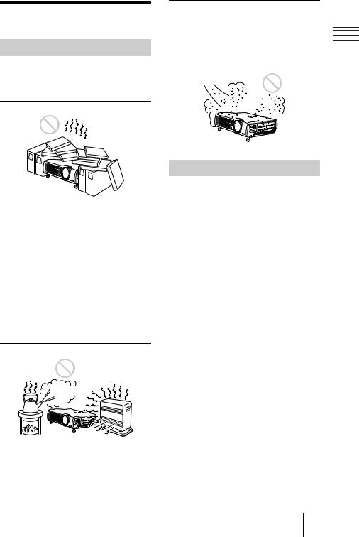
Poorly ventilated
•Allow adequate air circulation to prevent internal heat build-up. Do not place the unit on surfaces (rugs, blankets, etc.) or near materials (curtains, draperies) that may block the ventilation holes.
•When the internal heat builds up due to the block-up, the temperature sensor will function with the message “High temp.! Lamp off in 1 min.” The power will be turned off automatically after one minute.
•Leave space of more than 30 cm (11 7/8 inches) around the unit.
•Be careful that the ventilation holes may inhale tininess such as a piece of paper.
Highly heated and humid
•Avoid installing the unit in a location where the temperature or humidity is very high, or temperature is very low.
•To avoid moisture condensation, do not install the unit in a location where the temperature may rise rapidly.
Very dusty
Avoid installing the unit in a location where there is a lot of dust; otherwise, the air filter will be obstructed. The dust blocking the air
through the filter may cause raising the |
|
|
|
||
internal heat of the projector. Clean it up |
|
|
Overview |
||
periodically. |
||
|
Usage in High Altitude
When using the projector at an altitude of 1,500 m or higher, turn on “High
Altitude Mode” in the INSTALL SETTING menu. Failing to set this mode when using the projector at high altitudes could have adverse effects, such as reducing
the reliability of certain components.
Notes on Installation 7 GB
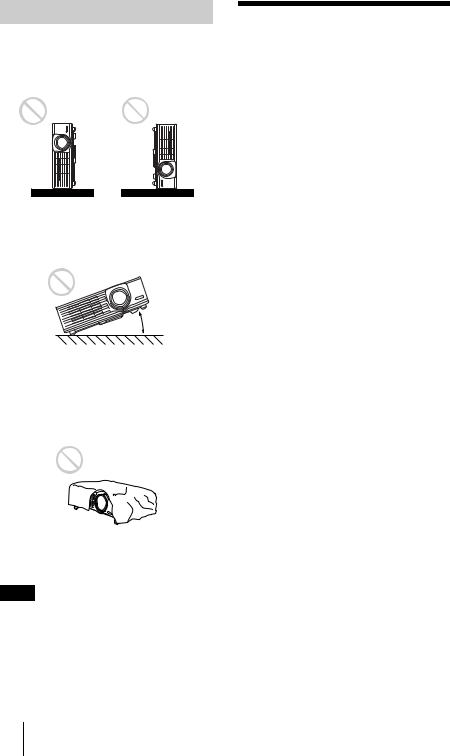
Unsuitable Conditions
Do not use the projector under the following conditions.
Toppling the unit.
Avoid using as the unit topples over on its side. It may cause malfunction.
Tilting right/left
20°
Avoid using as the unit tilts more than 20 degrees. Do not install the unit other than on the floor or ceiling. These installations may cause malfunction.
Blocking the ventilation holes
Avoid using something to cover over the ventilation holes (exhaust/intake); otherwise, the internal heat may build up.
Note
When using a screen with an uneven surface, stripes pattern may rarely appear on the screen depending on the distance between the screen and the projector or the zooming magnifications. This is not a malfunction of the projector.
Features
High brightness, high picture quality
•High brightness
This projector is equipped with a highefficiency optical system made possible by adopting Sony’s new proprietary optical system. Because the VPL-PX40 utilizes a newly developed high N.A. LCD panel with a microlens and a 265W UHP lamp, it can reproduce bright images at 3500 ANSI lumens, while the VPL-PX35 with no microlens can reproduce bright images at 2600 ANSI lumens.
•High resolution
Three 0.99-inch, about 790,000 pixel,
XGA panels provide a resolution of 1024 × 768 dots for RGB input and 750 horizontal TV lines for video input.
Easy Setup
•Permits setup on a front-to-back slope
This projector can be set up on a slope of up to 90 degrees up or down. The projector also permits rear projection using a mirror.
•Optional lenses
The projector can be adapted to a variety of different types of installations by using one of three lenses (sold separately), two with a short focus and one with a long focus.
•Direct Power On/Power Off function
The AC power for the entire system can be turned on and off by means of a breaker or other switch.
•System expandability (network compatibility)
In addition to conventional serial control using an RS-232C connector, this projector also supports connection to an network environment through an Ethernet connector. This function can be used to control multiple projectors and also makes it possible to acquire status information from each projector, such as the length of time the lamp has been on.
GB 8 Features

(For details on the network functions, contact your dealer or the Sony customer service.)
Convenient presentation functions
•Equipped with USB connector
Simply by connecting the projector to a computer through the USB interface, the Remote Commander provided with the projector can then be used as a wireless mouse.
•Remote Commander with laser pointer
The Remote Commander comes equipped with a laser pointer that is useful when making presentations.
Accepts various input signals
•Equipped with DVI connector and 5BNC connector
The projector is equipped with a DVI-D connector that can be used to connect a digital RGB device.
The projector is also equipped with a 5BNC input connector that supports highprecision signal connection with a workstation or other device, as well as long-distance transmission.
•Scan converter loaded
This projector has a build-in scan
converter that converts the input signal within 1,024 × 768 dots.
•Compatible input signals
This projector accepts video signals of composite, S video, and component as well as 15k RGB, VGA, SVGA, XGA, SXGA, SXGA+ and UXGA (60 Hz) signals, which all can be displayed. In this projector, 46 types of input signals are preset.
•Compatible with six color systems
NTSC, PAL, SECAM, NTSC4.431), PAL- M, or PAL-N color system can be selected automatically or manually.
1)NTSC4.43 is the color system used when playing back a video recorded on NTSC
on a NTSC4.43 system VCR.
...............................................................................
•Windows is a registered trademark of Microsoft Corporation in the United States and/or other countries.
•IBM PC/AT, VGA, SVGA, XGA, SXGA and UXGA are registered trademarks of
the International Business Machines
Corporation, U.S.A.
•Kensington is a registered trademark of Kensington Technology Group.
•Macintosh is a registered trademark of Apple Computer, Inc.
•VESA is a registered trademark of Video Electronics Standard Association.
•Display Data Channel is a trademark of Video Electronics Standard Association.
Overview
Features 9 GB

Location and
Function of Controls
Front/Left Side
Rear/Right Side/Bottom |
a Handle
bZoom ring
Adjusts the picture size.
cControl panel
For details, see “Control Panel” on page 12.
dConnector panel
For details, see “Connector Panel” on page 13.
eAC IN socket
Connects the supplied AC power cord.
f Front remote control detector
gLens
Remove the lens cap before projection.
h Ventilation holes (exhaust)
iFocus ring
Adjusts the picture focus.
j Rear remote control detector
kIndicators
•LAMP/COVER: Lights up or flashes under the following conditions:
–Lights up when the lamp has reached the end of its life or becomes a high temperature.
–Flashes when the lamp cover or air filter cover is not secured firmly.
•TEMP (Temperature)/FAN: Lights up or flashes under the following conditions:
–Lights up when temperature inside the projector becomes unusually high.
–Flashes when the fan is broken.
For details on the LAMP/COVER and the TEMP/FAN indicators, see on page 43.
•POWER SAVING: Lights up when the projector is in power saving mode. When POWER SAVING in the SET SETTING menu is set to ON, the projector goes into power saving mode if no signal is input for 10 minutes.
GB 10 Location and Function of Controls
Although the lamp goes out, the cooling fan keeps running. The power saving mode is canceled when a signal is input or any key is pressed. In power saving mode, any key does not function for the first 60 seconds after the lamp goes out.
•ON/STANDBY: Lights up or flashes under the following conditions:
–Lights in red when a AC power cord is plugged into a wall outlet. Once in standby mode, you can turn on the projector with the I / 1 key.
–Lights in green when the power is turned on.
–Flashes in green while the cooling fan runs after the power is turned off with the I / 1 key. The fan runs for about 90 seconds after the power is turned off.
The ON/STANDBY indicator flashes quickly for the first 60 seconds. During this time, you cannot light up the ON/STANDBY indicator with the I / 1 key.
l Lamp cover
mSecurity lock
Connects to an optional security cable (Kensington’s).
Home page address: http://www.kensington.com/
nAdjuster adjustment buttons
For details, see “How to use the adjuster” on page 11.
o Adjuster
p Speaker
qVentilation holes (intake)/air filter cover
•Do not place anything near the ventilation holes as it may cause internal heat build-up.
•Do not place your hand or objects near the ventilation holes as it may cause the air coming out heat build-up.
Note
• To maintain optimal performance, clean the air filter every 1500 hours.
For details, see “Cleaning the Air
Filter” on page 39.
|
Overview |
|
How to use the adjuster |
||
|
||
To adjust the height |
|
Adjusts the height of the projector as follows:
1 Lift the projector and press the adjuster adjustment buttons.
The adjusters will extend from the projector.
Adjuster adjustment buttons
2 While pressing the buttons, adjust the projector to the desired height, and then release the buttons. For fine adjustment, turn the adjusters to the right and the left.
to lower |
to raise the |
the |
projector |
projector |
|
Notes
•Be careful not to let the projector down on your fingers.
•Do not push hard on the top of the projector with the adjusters out.
It may be occurred malfunction.
Location and Function of Controls 11 GB
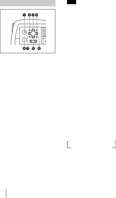
Control Panel
MENU |
APA |
|
CONT |
I / |
ET |
|
ENTER RESET
INP
INPUT VOLUME
INP
a I / 1 (on/standby) key
Turns on and off the projector when the projector is in standby mode. The ON/ STANDBY indicator lights in green when the power is turned on.
When turning off the power, press the I / 1 key twice following the message on the screen, or press and hold the key for about one second.
For details on steps for turning off the power, see “To turn off the power” on page 28.
bMENU key
Displays the on-screen menu. Press again to clear the menu.
cArrow keys (M/m/</,)
Used to select the menu or to make various adjustments.
dAPA (Auto Pixel Alignment) key
Pressing this key while a signal from a computer is being input automatically adjusts the picture so that it can be seen clearly. This function also simultaneously adjusts the screen size and makes up/down and left/right shift adjustments.
Note
Press the APA key when the full image is displayed on the screen. If the projected image includes a large black area around the periphery, the APA function will not function properly and in some cases, portions of the image may not be displayed.
•You can cancel the adjustment by pressing the APA key again while “Adjusting” appears on the screen.
•The picture may not be adjusted properly depending on the kinds of input signals.
•Adjust the items “Dot Phase,” “H Size” and “Shift” in the INPUT SETTING menu when you adjust the picture manually.
eRESET key
Resets the value of an item back to its factory preset value. This key functions when the menu or a setting item is displayed on the screen.
fVOLUME +/– key
Adjusts the volume of the built-in speakers and output level of the AUDIO jack.
+: Increases the volume. –: Decreases the volume.
gENTER key
Enters the settings of items in the menu system.
hINPUT key
Selects the input signal. Each time you press the key, the input signal switches as follows:
tINPUT A t INPUT B t INPUT C t
S VIDEO T VIDEO T INPUT D
The audio signals are common to the INPUT B, INPUT C, VIDEO and S-VIDEO.
GB 12 Location and Function of Controls
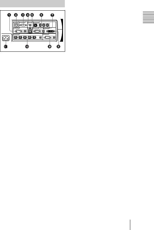
Connector Panel
MENU |
ENTER |
CONTROL |
REMOTE |
CONTROL S |
VIDEO IN |
|
|
|
|
||
|
|
|
|
|
|
||||||
|
|
ETHER |
|
RS-232C |
IN |
S VIDEO |
VIDEO |
AUDIO |
|
||
APA |
RESET |
|
|
|
(PLUS IN POWER) |
|
|
L |
R |
|
|
|
|
|
|
|
|
(MONO) |
|
|
|||
|
|
INPUT A |
|
|
|
INPUT B |
INPUT C |
|
|
||
|
VOLUME |
RGB |
AUDIO |
|
RGB |
AUDIO |
|
DVI-D |
|
||
~AC IN |
INPUT D |
|
|
|
|
OUTPUT |
|
|
|||
R/R-Y/Pn |
G/Y |
B/B-Y/Ps SYNC/HD |
VD |
AUDIO |
MONITOR |
AUDIO |
|||||
|
|
||||||||||
a INPUT A connectors |
|
|
|
||||||||
Connect to a computer.
•HD D-sub 15-pin, female:
Connect to the monitor output on a computer using the supplied cable.
•AUDIO (stereo mini-jack): Connects to the audio output on a computer.
bETHER (RJ-45)
Connects to the LAN cable when the network function is in use.
Consult the dealer for connection and installation.
cRS-232C connector (D-sub 9- pin, female)
Connects to a computer to operate the projector from the computer.
dCONTROL S IN/PLUG IN POWER (DC 5V output) jack
Connects to the control S out jacks of the Sony equipment. Connects to the CONTROL S OUT jack on the supplied Remote Commander when using it as a wired Remote Commander. In this case, when a stereo cable is used, you do not need to install the batteries in the Remote Commander, since the power is supplied from this jack.
eUSB connector (USB plug for upstream, 4-pin)
Connects to the USB connector on a computer. When you connect the projector to the computer, you can control the mouse function with the supplied Remote Commander.
fVideo input connectors
Connect to external video equipment such as a VCR.
•S VIDEO (mini DIN 4-pin):
Connects to the S video output (Y/C video output) of video equipment.
•VIDEO (phono type): Connects to the composite video output of video equipment.
•AUDIO input L (MONO)/R (phono type): Connect to the audio output of equipment. For stereo equipment, use both the L and R jacks; for monaural equipment, use the L (MONO) jack only.
gINPUT B connectors
Connect to a computer.
•HD D-sub 15-pin, female:
Connects to the monitor output on a computer using the supplied cable.
•AUDIO (stereo mini-jack)/Shared by INPUT B and C: Connects to the audio output on a computer.
hINPUT C connector (RGB (DVI)) (DVI-D)
Connects to a computer equipped with DVI (digital) output connector with a DVI cable.
iOUTPUT connectors MONITOR (HD D-sub 15-pin, female):
Connect to the video input connector on the monitor. Outputs signals from the selected channel and computer signals only from among the signals from the INPUT A, INPUT B, or INPUT D RGB connector. This connector does not output any signals from the INPUT C connector.
•AUDIO (stereo mini-jack): Connects to external active speakers. The volume of the speakers can be controlled by the VOLUME +/– keys on the Remote Commander or the VOLUME +/– keys on the control panel.
Overview
Location and Function of Controls 13 GB
jINPUT D, 5BNC input connectors (R/R-Y/PR, G/Y, B/B- Y/PB, SYNC/HD, VD connectors) (BNC type):
Connect to a high-resolution computer or VCR where signals are transmitted long distances; for example, when the projector has been hung from the ceiling.
According to the connected equipment, computer, component (R-Y/Y/B-Y), HDTV or DTV (DTV GBR, DTV YPBPR) signal is selected.
•AUDIO (stereo mini-jack): Connects to the audio output on a computer.
kAC IN socket
Connects the supplied AC power cord.
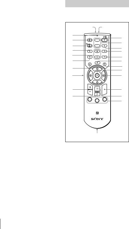
Remote Commander
The keys which have the same names as on the control panel function identically.
|
wg |
wh |
|
wf |
COMMAND |
|
1 |
wd |
OFF ON |
|
|
PIC |
|
||
|
2 |
||
PJ NETWORK MUTING |
|
||
ws |
|
||
|
|
||
AUDIO |
INPUT |
3 |
|
|
|
||
wa |
|
D KEYSTONE |
|
LENS |
|
4 |
|
w; |
VOLUME |
|
|
|
5 |
||
APA |
HELP |
||
ql |
MENU/ |
LASER |
6 |
TAB |
|||
|
FREEZE |
|
7 |
qk |
|
|
|
|
|
8 |
|
|
|
|
|
qj |
|
|
9 |
qh |
ENTER |
R |
q; |
|
CLICK |
||
qg |
RESET/ |
|
qa |
ESCAPE |
|
||
D ZOOM |
|
||
|
|
||
|
1 |
3 |
qs |
|
2 |
|
|
|
FUNCTION |
|
|
|
|
|
|
|
RM-PJM15 |
|
|
|
PROJECTOR |
|
|
|
qd,qf |
|
|
a I / 1 key |
|
|
|
bMUTING keys
Cut off the picture and sound.
•PIC: Cuts off the picture. Press again to restore the picture.
•AUDIO: Press to temporarily cut off the audio output from the speaker, and the output on the AUDIO jack in the OUTPUT section.
Press again or press the VOLUME + key to restore the sound.
c INPUT key
GB 14 Location and Function of Controls

dD KEYSTONE key
Corrects the trapezoidal distortion caused by the projection angle. Use the arrow keys (M/m/</,) to display the image as a rectangle.
eHELP key
This function is not provided in this projector.
fFREEZE key
This key freezes the projected image. Press again to unfreeze the image.
gLASER key
Emits laser beam from the laser transmitter when you press this key.
hJoy stick
Functions as a mouse of a computer connected to the unit.
i Arrow keys (M/m/</,)
jR CLICK key
Functions as a right button on a mouse of a computer connected to the unit.
k ENTER key
lFUNCTION 1/2/3 keys
This key does not work in the unit.
mStrap holder
Attaches the supplied strap.
nCONTROL S OUT jack (stereo mini-jack)
Connects to the CONTROL S IN jack on the projector with the connecting cable (not supplied) when using the Remote Commander as a wired one. In this case, you do not need to install the batteries since the power is supplied via the CONTROL S IN jack on the projector.
oRESET/ESCAPE key
Functions as a RESET key.
pD ZOOM +/– key
Enlarges the image at a desired location on the screen.
+: Pressing the + key once displays the icon. This icon indicates the point you want to enlarge. Use an arrow key (M/ m/</,) to move the icon to the point to be enlarged. Press the + key repeatedly until the image is enlarged to your requirements.
–: Pressing the – key reduces an image that has been enlarged with the D ZOOM + key.
qL CLICK key
Functions as a left button on a mouse of a computer connected to the unit.
rMENU/TAB key
Functions as a MENU key.
s APA (Auto Pixel Alignment) key t VOLUME +/– keys
uLENS key
This function is not provided in this projector.
vPJ/NETWORK (Projector/ Network) selector switch
Set this switch to PJ always.
wCOMMAND ON/OFF switch
When this switch is set to OFF, no key on the Remote Commander function. This saves the battery power.
xTransmission indicator
Lights up when you press a key on the Remote Commander.
This indicator does not light up when you use the laser pointer.
y Infrared transmitter z Laser transmitter
Overview
Location and Function of Controls 15 GB
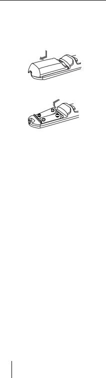
Battery installation
1 Push and slide to open the lid, then install the two size AA (R6) batteries (supplied) with the correct polarity.
While pressing the lid, slide it.
Be sure to install the battery from the # side.
2 Replace the lid.
Notes on batteries
•Make sure that the battery orientation is correct when inserting batteries.
•Do not mix an old battery with a new one or different types of batteries.
•If you will not use the Remote Commander for a long time, remove the batteries to avoid damage from battery leakage. If batteries have leaked, remove them, wipe and dry the battery compartment, and replace the batteries with new ones.
Notes on laser beam
•Do not look into the laser transmitter.
•Do not aim the laser at people.
Notes on Remote Commander operation
•Make sure that nothing to obstruct the infrared beam between the Remote Commander and the remote control detector on the projector.
•The operation range is limited. The shorter the distance between the Remote Commander and the projector is, the wider the angle within which the commander can control the projector.
GB 16 Location and Function of Controls
B Setting Up and Projecting
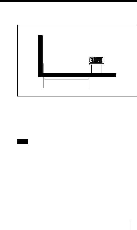
Installing the Projector
This section describes how to install the projector.
The distance between the lens and the screen varies depending on the size of the screen. Use the following table as a guide.
Distance between the screen and the center of the lens
Unit: m (ft) |
|
|
|
|
|
|
|
|
Screen size |
40 |
60 |
80 |
100 |
120 |
150 |
200 |
300 |
(inches) |
|
|
|
|
|
|
|
|
Minimum |
1.5 |
2.3 |
3.0 |
3.8 |
4.6 |
5.8 |
7.7 |
11.6 |
Distance |
(4.9) |
(7.5) |
(10.0) |
(12.5) |
(15.0) |
(19.0) |
(25.2) |
(37.9) |
Maximum |
1.9 |
2.9 |
3.8 |
4.8 |
5.8 |
7.2 |
9.7 |
14.5 |
Distance |
(6.2) |
(9.5) |
(12.5) |
(15.7) |
(19.0) |
(23.6) |
(31.7) |
(47.6) |
Note
For details on ceiling installation, consult with qualified Sony personnel.
Projecting and Up Setting
Installing the Projector 17 GB
 Loading...