


VPL-FHZ65 BJ

4-573-698-12 (1)
© 2015 Sony Corporation
Data
Projector
Operating Instructions
Before operating the unit, please read this manual and supplied Quick Reference Manual
thoroughly and retain it for future reference.
VPL-FHZ65/FHZ60
Not all models are available in all countries and area. Please check
with your local Sony Authorized Dealer.

2
Table of Contents
Overview
Location and Function of Controls .... 4
Main Unit ..................................... 4
Terminals ..................................... 5
Remote Commander and Control
Panel ......................................... 6
Preparation
Connecting the Projector ................... 9
Connecting a Computer ............... 9
Connecting Video Equipment .... 10
Connecting an External Monitor and
Audio Equipment ................... 12
Connecting Network
Equipment .............................. 13
Connecting to HDBaseT™
Equipment .............................. 14
Attaching the terminal cover ...... 16
Projecting/Adjusting an
Image
Projecting an Image ......................... 17
Adjusting the Focus, Size, and
Position of the Projected
Image ...................................... 18
Correcting for Trapezoidal
Distortion of the Projected Image
(Keystone Adjustment) ........... 19
Correcting Image Twist (Warp
Correction Feature) ................. 20
Blending Projections from Multiple
Projectors on a Screen ............ 21
Turning Off the Power ............... 22
Adjustments and Settings
Using a Menu
Using a Menu ...................................23
The Picture Menu .............................24
The Screen Menu .............................27
The Function Menu ..........................30
The Operation Menu ........................31
The Connection/Power Menu .......... 33
The Installation Menu ......................35
The Information Menu .....................38
Network
Using Network Features ................... 39
Displaying the Control Window of
the Projector with a Web
Browser ................................... 39
Confirming the Information
regarding the Projector ............40
Operating the Projector from a
Computer ................................. 40
Using the e-mail Report
Function .................................. 40
Setting the LAN Network of the
projector .................................. 42
Setting the Control Protocol of the
Projector .................................. 43
Others
Indicators .......................................... 46
Messages List ...................................48
Troubleshooting ...............................49
Cleaning the Air Filter .....................51
Replacing the Projection Lens ......... 52
Removing ................................... 52

3
Attaching .................................... 53
Specifications .................................. 54
Projection Distance and Lens Shift
Range ........................................... 61
Dimensions ...................................... 64
Index ................................................ 68
4
B Overview
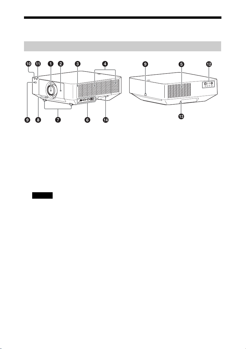
Location and Function of Controls
a Lens (page 52)
b Front panel
c Side cover (page 51)
d Ventilation holes (intake)
e Ventilation holes (exhaust)
Do not place anything near the ventilation
holes as this may cause internal heat
buildup. Do not place your hand near the
ventilation holes (exhaust) and the
circumference as this may cause injury.
f Terminals (page 5)
g Front feet (adjustable) (page 18)
h LENS RELEASE button
(page 52)
i Remote control receiver
The remote control receivers are located
at the front and rear of the projector.
j ON/STANDBY indicator
(page 46)
k WARNING indicator (page 46)
l Control panel (page 6)
m Antitheft lock
Connects to an optional antitheft cable
manufactured by Kensington.
For details, visit the Kensington’s web
site.
http://www.kensington.com/
n Antitheft bar
Connects to a commercially available
antitheft chain or wire.
Main Unit
Caution
5
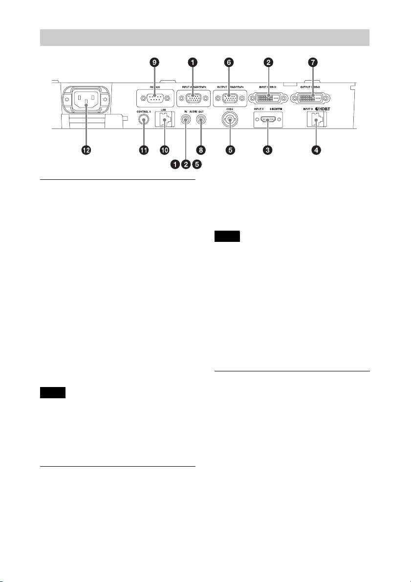
Input (page 9)
a INPUT A
Video: RGB/YPBPR input terminal
(RGB/YP
BPR)
Audio: Audio input terminal (AUDIO)
b INPUT B
Video: DVI-D input terminal (DVI-D)
Audio: Audio input terminal (AUDIO)
c INPUT C
Video: HDMI input terminal (HDMI)
Audio: HDMI input terminal (HDMI)
d INPUT D
HDBaseT terminal
e VIDEO (VIDEO IN)
Video: Video input terminal
Audio: Audio input terminal (AUDIO)
• The audio input terminals of the projector are
for output to external equipment.
Connect
external audio equipment to output audio
(page 12).
• The audio inputs of INPUT A, INPUT B, and
VIDEO are shared.
Output (page 12)
f OUTPUT A
Video: RGB/YPBPR output terminal
(RGB/YP
BPR)
Audio: Audio output terminal (AUDIO)
g OUTPUT B
Video: DVI-D output terminal (DVI-D)
h AUDIO OUT
Audio: Audio output terminal (AUDIO)
These terminals output projected images or
audio. As for images, the signal input from
INPUT A is output from OUTPUT A, and the
signal input from INPUT B is output from
OUTPUT B. However, if the signal input from
INPUT B is protected by HDCP, the signal is
not output from INPUT B. As for audio, when
INPUT A or B, or VIDEO is selected, the audio
signal input from the audio input terminal is
output; when INPUT C or D is selected, the
audio signal input from the selected input
terminal is output.
Others
i RS-232C terminal
RS-232C compatible control terminal
j LAN terminal (page 13)
k CONTROL S input terminal (DC
power supply) (CONTROL S)
Connects to the CONTROL S output
terminal on the supplied Remote
Commander with a connecting cable
(stereo mini plug (not supplied)) when
using it as a wired Remote Commander.
You do not need to install batteries in the
Remote Commander, as the power is
supplied from this terminal.
Terminals
Notes
Note
6
l AC IN (-) socket
Connects the supplied AC power cord.
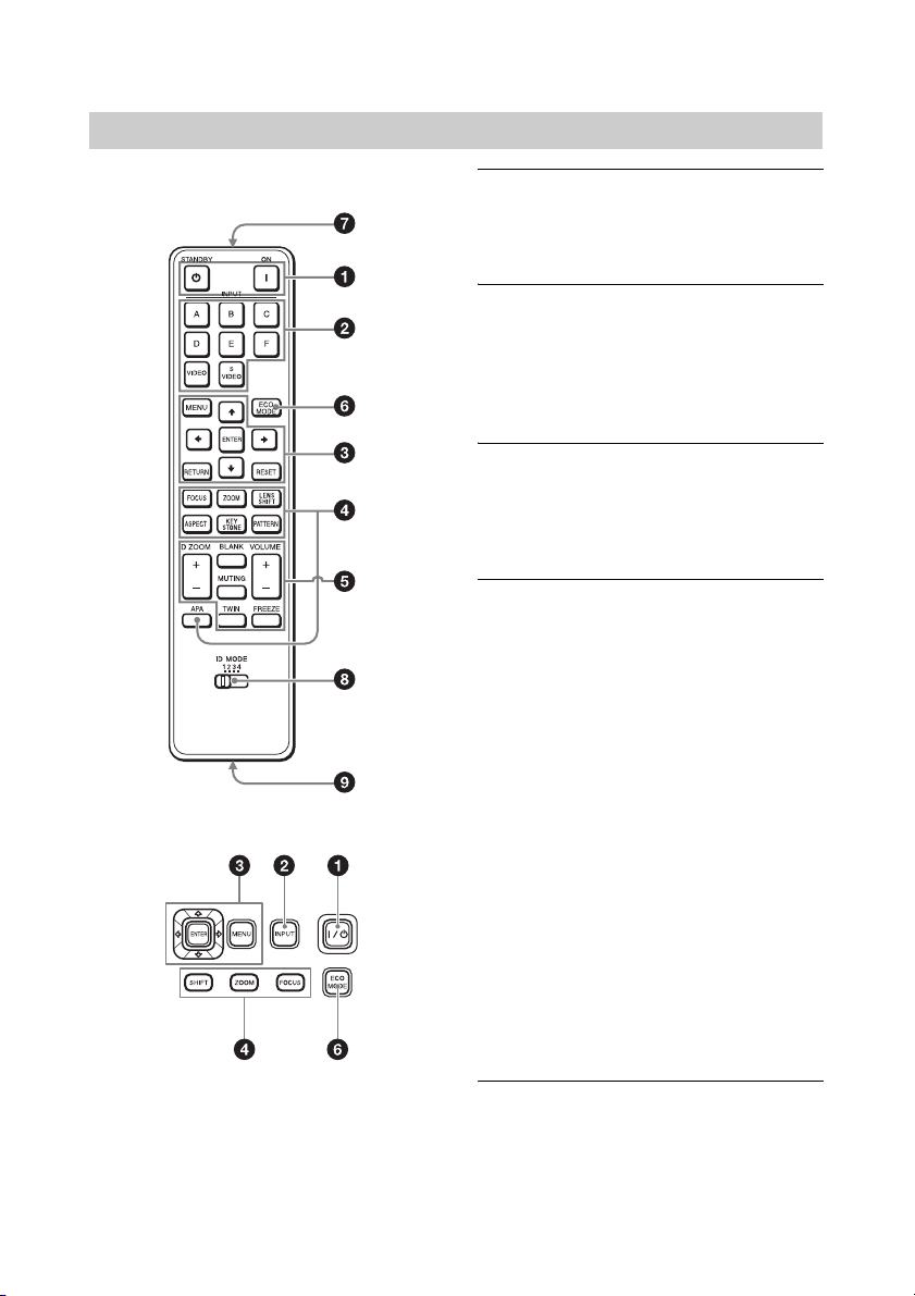
Remote Commander
Control Panel
a Turning on the power/Going to
standby
? (On) key
1 (Standby) key
b Selecting an input signal
(page 17)
INPUT key
Direct input select keys
The E, F, and S VIDEO keys are not used
with this projector.
c Operating a menu (page 23)
ENTER /V/v/B/b (arrow) keys
MENU key
RETURN key
RESET key
d Adjusting the image (page 18)
FOCUS key
Use this key when attaching the power
focus lens.
ZOOM key
Use this key when attaching the power
zoom lens.
LENS SHIFT/SHIFT key
ASPECT key (pages 27, 29)
Changes the aspect ratio of the projected
image.
KEYSTONE key (page 19)
PATTERN key (page 18)
APA (Auto Pixel Alignment) key
Automatically adjusts a picture to its
clearest while a signal from a computer
is input via the RGB input terminal
(INPUT A). You can cancel the
adjustment by pressing the APA key
again while adjusting.
e Using various functions during
projecting
D ZOOM (Digital Zoom) key
Enlarges a portion of the image while
projecting.
Remote Commander and Control Panel
7
Use this key when inputting a computer
signal. But it may not be enabled,
depending on the resolution of the input
signal and when displaying two pictures.
1 Press the D ZOOM + key to display
the digital zoom icon on the projected
image.
2 Press the V/v/B/b keys to move the
digital zoom icon to the point on the
image you wish to enlarge.
3 Press the D ZOOM + key or the D
ZOOM – key repeatedly to change the
enlargement ratio. The image can be
enlarged up to 4 times.
Press the RESET key to restore the
previous image.
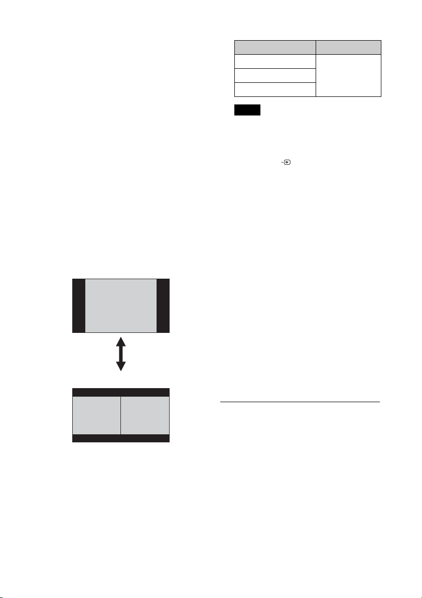
TWIN (Twin Picture) key
You can project the images from two
input signals on the screen as a main
picture and subpicture at the same time.
To switch between one and two pictures,
press the TWIN key.
You can select the image to project to the
main picture.
The subpicture is preset to source the
signal input from INPUT A. INPUT A is
only compatible with signals from
computers.
Combinations of input signals
• When “Screen Aspect” (page 36) is set
to “4:3,” the two picture function is not
available.
• When displaying two pictures, the input
signal icon does not appear in the
input select window (page 17).
• Picture settings set for one picture may
not be reflected as two pictures.
• When displaying two pictures, the ? (On)
key, 1 (standby) key, INPUT key, and
BLANK key are available.
BLANK key
Cuts off the image. Press again to restore
the image.
MUTING key
Mutes the audio output. Press again to
restore the previous volume.
VOLUME key
For adjusting the volume output from
the audio output terminal of the
projector.
FREEZE key
Pauses a projected image. Press again to
restore the image.
Use this key when inputting a computer
signal.
f Setting the energy–saving mode
easily
ECO MODE key
Energy-saving mode can be set easily.
Energy-saving mode consists of “With
No Input,” “With Static Signal” and
“Standby Mode.”
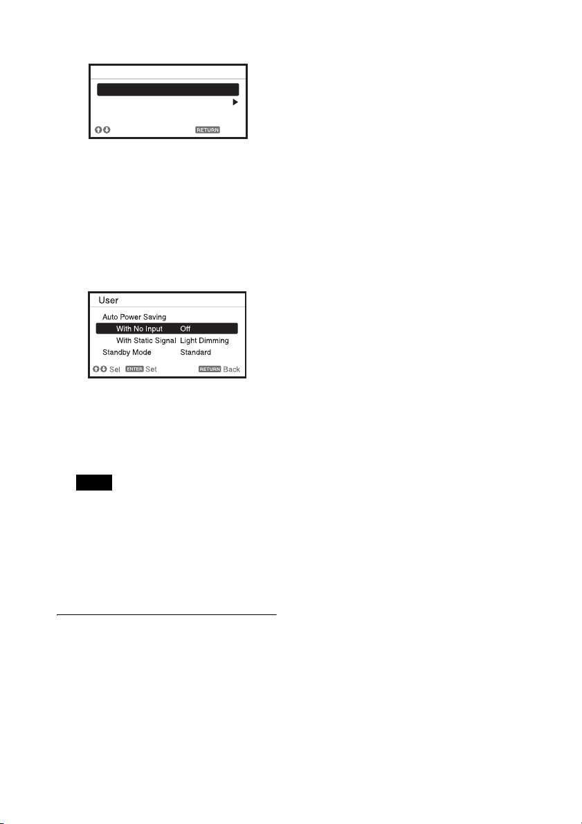
1 Press the ECO MODE key to display
the ECO Mode menu.
One picture display
TWIN key
Two pictures display
(A) Main picture (B) Subpicture
Main picture Subpicture
INPUT B (DVI-D)
INPUT A (RGB)INPUT C (HDMI)
INPUT D (HDBaseT)
Notes
8
2 Press the V/v key or ECO MODE key
to select “ECO” or “User” mode.
ECO: Sets each mode to the optimum
energy-saving value.
• With No Input: Standby
• With Static Signal: Light
Dimming
• Standby Mode: Low
User: Sets each item of the energy-
saving mode menu as you desire.
3 Press the RETURN key to restore the
previous image.
For details on ECO Mode settings, see
“With No Input,” “With Static Signal,”
and “Standby Mode” on the Connection/
Power menu (page 33).
If you set “ECO Mode” to “ECO,” or
“Standby Mode” (in “User”) to “Low,”
the network control function will be
disabled in standby mode. If the external
control is being performed by using the
network or network control function, do
not select “ECO,” or do not set “Standby
Mode” (in “User”) to “Low.”
Others
g Infrared transmitter
h ID MODE switch (page 31)
Sets an ID mode of the Remote
Commander. If you assign a different ID
number to each projector when multiple
projectors are used, you can control only
the projector with the same ID mode as
that of the Remote Commander.
i CONTROL S output terminal
Connects to the CONTROL S input
terminal on the projector with a
connecting cable (stereo mini plug (not
supplied)) when using the Remote
Commander as a wired one.
You do not need to install batteries in the
Remote Commander, as the power is
supplied from the projector.
About Remote Commander operation
• Direct the Remote Commander toward the
remote control receiver.
• The shorter the distance between the
Remote Commander and the projector is,
the wider the angle within which the
Remote Commander can control the
projector becomes.
• If there is any obstruction between the
Remote Commander and the remote
control receiver on the projector, the
projector may not be able to receive
signals from the Remote Commander.
Note
ECO
User
Sel Back
ECO Mode
ECO Mode menu
9
B Preparation
Connecting the Projector
• Turn off all equipment before making any connections.
• Use the proper cables for each connection.
• Insert the cable plugs firmly; Loose connections may reduce performance of picture signals or
cause a malfunction. When pulling out a cable, be sure to grip it by the plug, not the cable itself.
• For more information, refer also to the instruction manuals of the equipment you are connecting.
• Use a no-resistance audio cable.
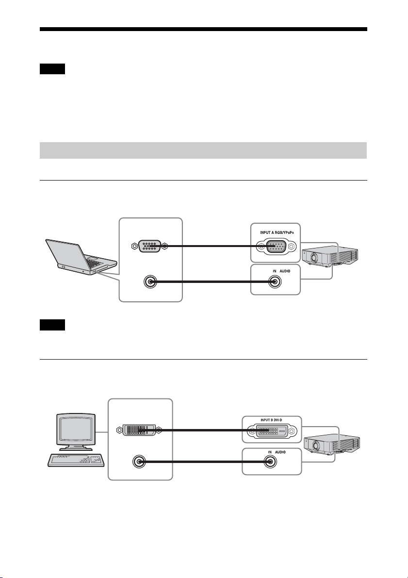
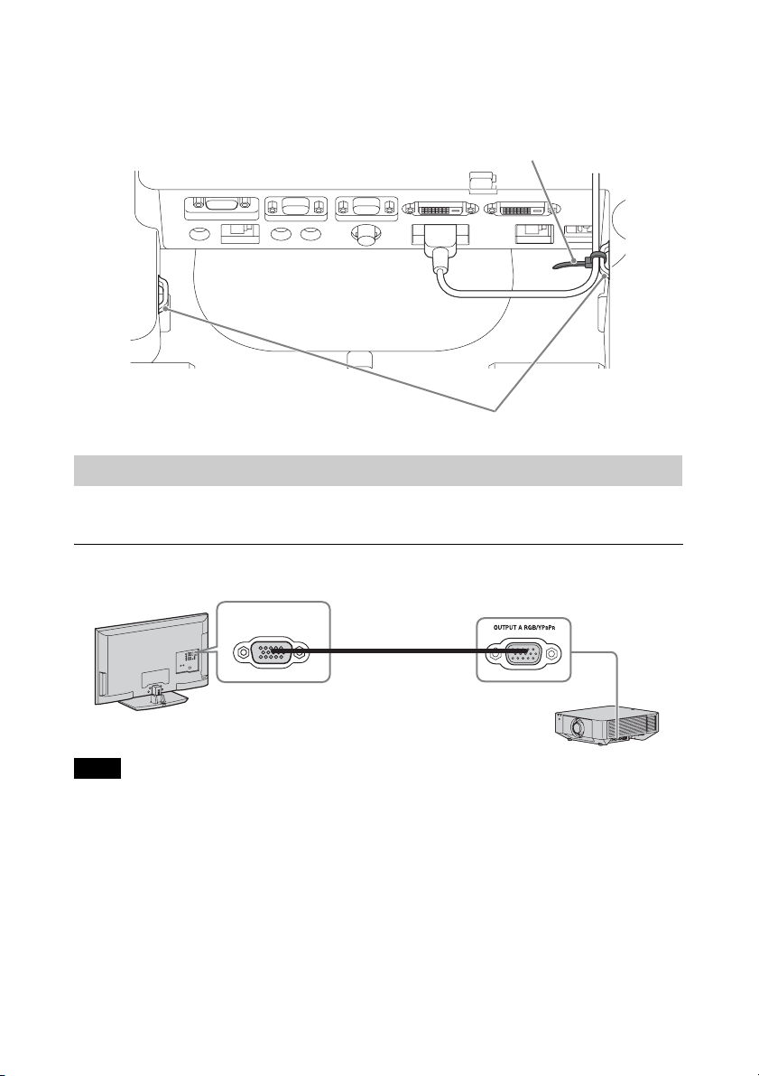
Connection with a computer is explained for each input signal.
INPUT A
For connecting a computer with an RGB output terminal.
It is recommended that you set the resolution of your computer to 1920 × 1200 pixels for the external
monitor.
INPUT B
For connecting a computer with a DVI-D output terminal.
Notes
Connecting a Computer
Note
Mini D-sub 15-pin
cable
(not supplied)
Audio cable
(Stereo mini plug)
(not supplied)
RGB output
terminal
Audio output
terminal
Computer
DVI-D cable
(not supplied)
DVI-D output
terminal
Computer
Audio output
terminal
Audio cable
(Stereo mini plug)
(not supplied)
10
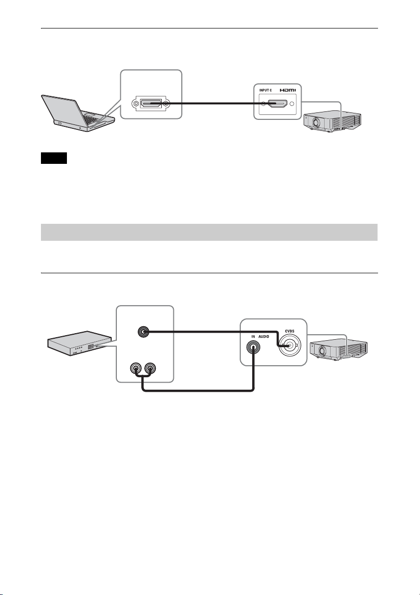
INPUT C
For connecting a computer with an HDMI output terminal.
• Use HDMI-compatible equipment which has the HDMI Logo.
• Use a high speed HDMI cable(s) on which the cable type logo is specified. (Sony products are
recommended.)
• The HDMI terminal of this projector is not compatible with DSD (Direct Stream Digital) signal or
CEC (Consumer Electronics Control) signal.
Connections with a VHS videocassette recorder, DVD player, or BD player are explained for
each input signal.
VIDEO IN
For connecting video equipment with a video output terminal.
Notes
Connecting Video Equipment
HDMI cable
(not supplied)
HDMI output
terminal
Computer
Video – BNC cable
(not supplied)
Audio cable (Phono plug × 2 – stereo mini plug) (not supplied)
Video output
terminal
Audio output
terminal
Video equipment
11
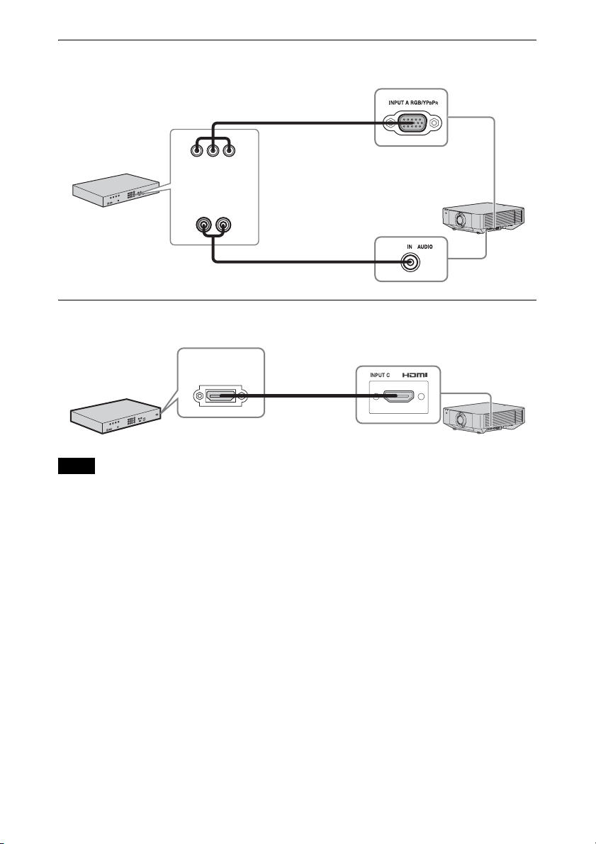
INPUT A
For connecting video equipment with a YPBPR output terminal.
INPUT C
For connecting video equipment with an HDMI output terminal.
• Use HDMI-compatible equipment which has the HDMI Logo.
• Use a high speed HDMI cable(s) on which the cable type logo is specified. (Sony products are
recommended.)
• The HDMI terminal of this projector is not compatible with DSD (Direct Stream Digital) signal or
CEC (Consumer Electronics Control) signal.
Notes
Component – Mini D-
sub 15-pin cable (not
supplied)
Audio cable (Phono plug
× 2 – stereo mini plug)
(not supplied)
Video equipment
YP
BPR output
terminal
Audio output
terminal
HDMI cable
(not supplied)
Video equipment
HDMI output
terminal
12
To fix the HDMI cable
Fix the cable to the cable tie holders at the sides of the terminals using a commercially available
cable tie, as shown in the illustration.
Use a cable tie of less than 1.9 mm × 3.8 mm in thickness.
Projected images and input audio can be output to display equipment such as a monitor and
audio equipment such as speakers with a built-in amplifier.
OUTPUT A
This terminal outputs projected images. The images are output when a computer signal or video
signal is input from the RGB/YP
BPR input terminal (INPUT A).
Connecting an External Monitor and Audio Equipment
Cable tie (commercially available)
Cable tie holders
Note
Mini D-sub 15-
pin cable
(not supplied)
RGB input
terminal
Display equipment
13
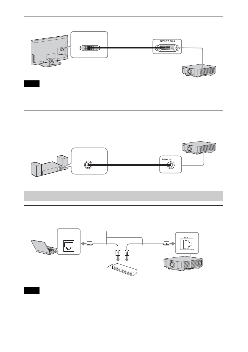
OUTPUT B
This terminal outputs projected images. The images are output when a computer signal is input
from the DVI-D input terminal (INPUT B). However, if the signal input from INPUT B is
protected by HDCP, the signal is not output to OUTPUT B.
AUDIO outpu t
When INPUT A or B, or VIDEO is selected, the audio input from the audio input terminal is
output; when INPUT C or D is selected, the audio input from the selected input terminal is
output.
Connecting network equipment
LAN terminal
When using network features via the LAN terminal, be sure to check if “LAN Setting” is set to
“LAN Port” (page 33).
Note
Connecting Network Equipment
Note
Display equipment
DVI-D input
terminal
DVI-D cable (not
supplied)
Audio equipment
Audio input
terminal
Audio cable (stereo mini
plug) (not supplied)
Computer
LAN
terminal
LAN cable (straight type) (not supplied)
Hub, router, etc
14
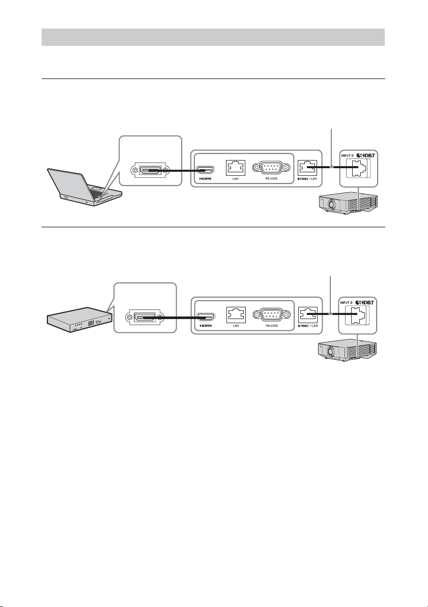
For connecting the computer, video equipment, and network equipment via the HDBaseT
transmitter.
Connecting to the computer
INPUT D
Connecting to video equipment
INPUT D
Notes for connecting this unit and the HDBaseT transmitter
• Ask a professional or Sony dealer to perform wiring. If wiring is not correct, the transmission
characteristics of the cable will not be achieved, and image or sound may break up or you
may experience unstable performance.
• Connect the cable directly to the HDBaseT transmitter without going through a hub or router.
• Use cables that meet the following conditions.
- CAT5e or higher
- Shielded type (covering connectors)
- Straight wire connection
-Single wire
• When installing the cables, use a cable tester, cable analyzer, or similar device to check if the
cables meet the CAT5e or higher requirement. If there is a transit connector between this unit
and the HDBaseT transmitter, include it when measuring.
• To reduce the affect of noise, install and use the cable in a manner where it is not rolled up
and it is as straight as possible.
• Install the cable away from the other cables (especially the power cable).
• When installing multiple cables, do not bind them and keep the running parallel distance as
short as possible.
Connecting to HDBaseT™ Equipment
Computer
HDMI output
terminal
HDMI cable (not supplied)
HDBaseT transmitter
LAN cable: STP type (CAT5e or
higher, straight, not supplied)
Video equipment
HDMI output
terminal
HDMI cable (not supplied)
HDBaseT transmitter
LAN cable: STP type (CAT5e or
higher, straight, not supplied)
15
• The transmittable distance of the cable is 100 m (approx. 328 feet) maximum. If it exceeds
100 m (approx. 328 feet), it may cause the image or the sound to break up, or cause a
multifunction in LAN communication. Do not use the HDBaseT transmitter beyond the
transmittable distance.
• Inquire about operation or function problems caused by other manufacturer’s devices with
the relevant manufacturer.
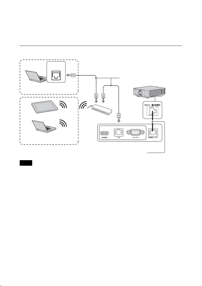
Connecting to network equipment
For connecting to network equipment via the HDBaseT terminal to control the projector.
• When using network features, be sure to check if “LAN Setting” is set to “via HDBaseT”
(page 33).
• Connect this unit and the HDBaseT transmitter directly without a hub or router.
Notes
Computer
LAN
terminal
Wired connection
LAN cable (straight type)
(not supplied)
Hub, wireless router
HDBaseT transmitter
Tablet PC/Smartphone
Computer
Wireless connection
LAN cable: STP type (CAT5e or
higher, straight, not supplied)
16
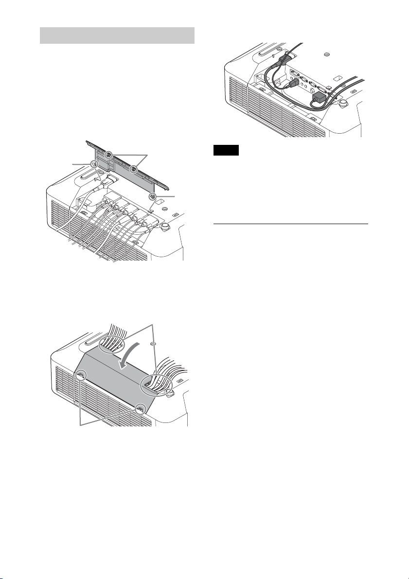
You can attach the supplied terminal cover to
prevent dust from entering the terminals to
maintain a neat appearance.
1 Fit one shaft on the side of the terminal
cover into the hole on the bottom, then
fit the other shaft by bending the cover
slightly.
2 Close the terminal cover.
Close the terminal cover until the two
tabs on the terminal cover click.
The terminal cover may not be attached
depending on the installation method, such
as due to the condition of the connected
cables or when installing the unit on the
floor. However, this has no impact on normal
use.
Opening the terminal cover
Raise the cover by inserting your fingers into
the finger hooks.
Attaching the terminal cover
Ta bs
Shaft
Shaft
Openings for cables
Finger hooks
Note
Example of the cable layout in the cover
17
B Projecting/Adjusting an Image
Projecting an Image
The size of a projected image depends on the distance between the projector and screen. Install
the projector so that the projected image fits the screen size. For details on projection distances
and projected image sizes, see
“Projection Distance and Lens Shift Range” (page 61).
1 Plug the AC power cord into a wall
outlet.
2 Connect all equipment to the projector
(page 9).
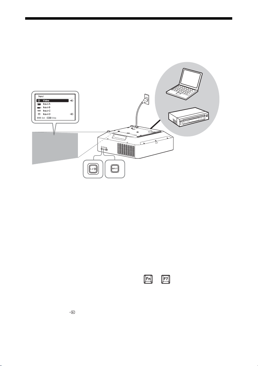
3 Turn on the projector.
Press the ?/1 key on the main unit or the
? key on the Remote Commander.
4 Turn on the connected equipment.
5 Select the input source.
Press the INPUT key on the projector to
display the input select window. Press
the INPUT key repeatedly or the V/v
key to select an image to be projected.
The signal icon appears on the right
side in the input select window when a
signal is input.
You can select the input source using
Direct input select keys on the Remote
Commander
(page 6).
6 Switch your computer to output to
external display by changing your
computer’s setting.
How to switch the computer to output to
the projector varies, depending on the
type of computer.
(Example)
7 Adjust the focus, size, and position of
the projected image (page 18).
Computer
Video equipment
Projector
Wall outlet
1
2
3
5
4
6
Input select window
5
+
18
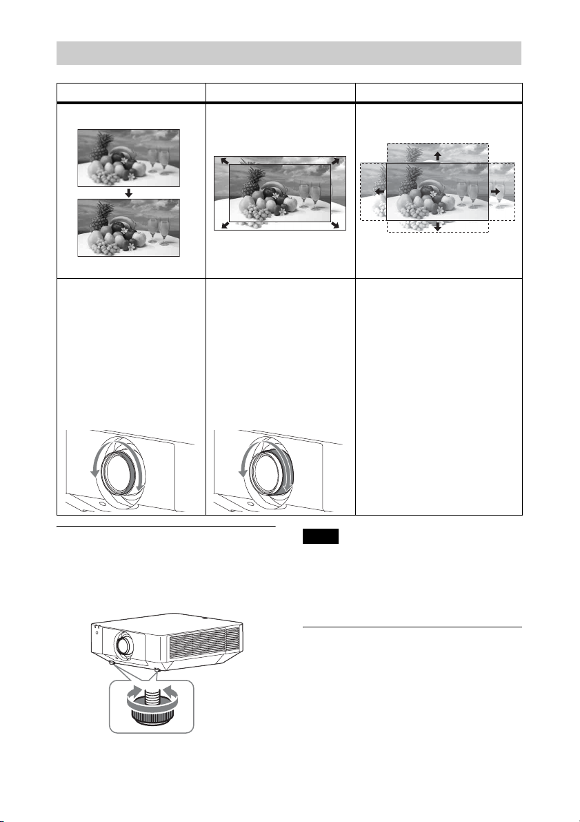
Adjusting the tilt of the projector
with the front feet (adjustable)
When the projector is installed on an uneven
surface, you can adjust using the front feet
(adjustable).
• Be careful not to let the projector down on
your fingers.
• Do not push hard on the top of the projector
with the front feet (adjustable) extended. It
may cause a malfunction.
Displaying a pattern for adjusting
an image
You can display a pattern for adjusting the
projected image with the PATTERN key on
the Remote Commander. Use V/v to change
the pattern and B/b to change its color.
Press the PATTERN key again to restore the
previous image.
Adjusting the Focus, Size, and Position of the Projected Image
Focus Size (Zoom) Position (Lens shift)
When attaching the Electric
focus lens
Press the FOCUS key on the
projector or the Remote
Commander then press the V/
v/B/b key to adjust the focus.
When attaching the Manual
focus lens
Turn the Focus Ring to adjust
the focus.
When attaching the Electric
zoom lens
Press the ZOOM key on the
projector or the Remote
Commander then press the V/
v/B/b key to adjust the size.
When attaching the Manual
zoom lens
Turn the Zoom Ring to adjust
the size.
Press the LENS SHIFT/SHIFT
key on the projector or the
Remote Commander then press
the V/v/B/b key to adjust the
position.
To return the lens to the center
position of the projected image
Press the RESET key on the
Remote Commander while
adjusting.
Notes
19
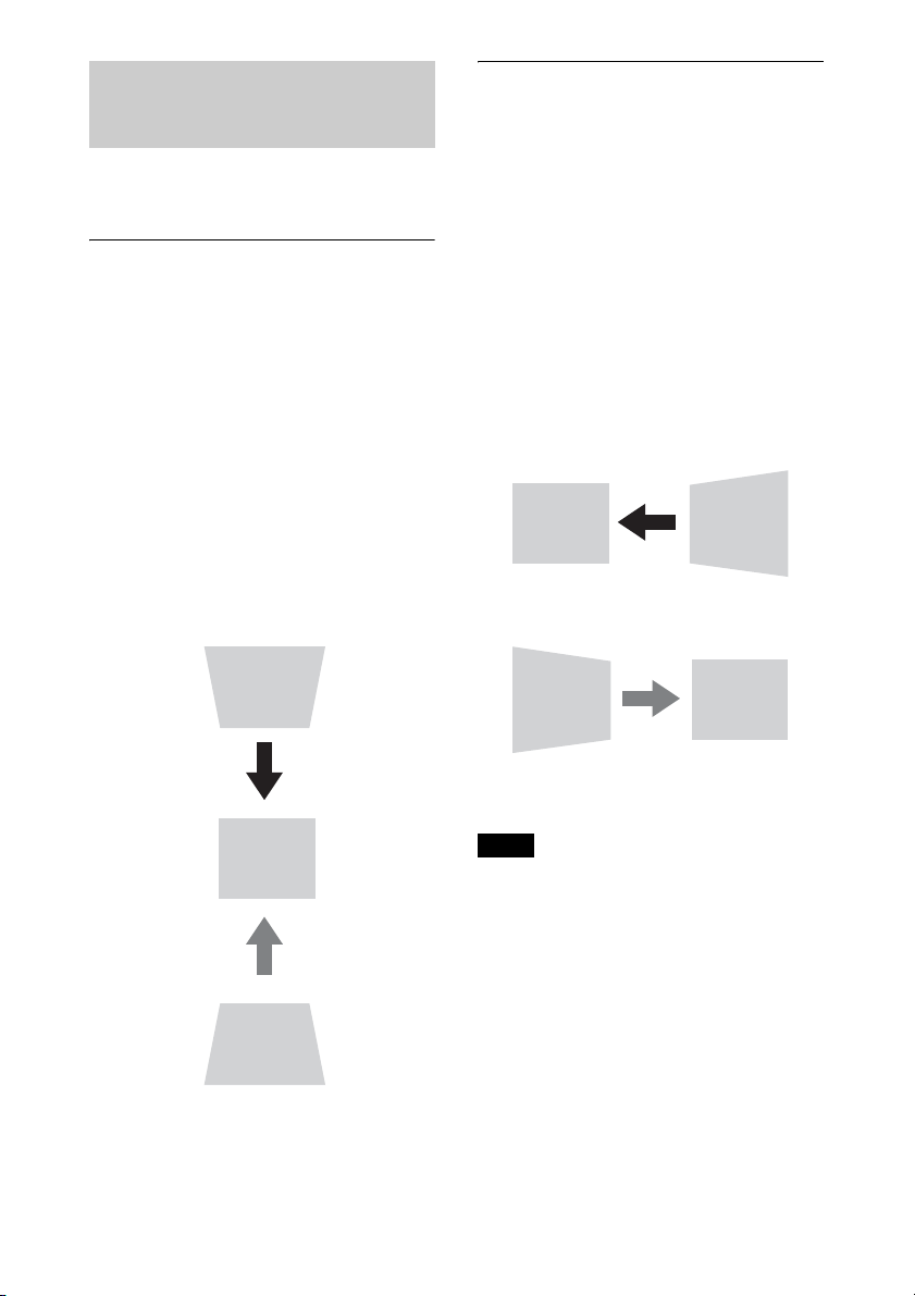
If the screen is tilted, or you are projecting
from an oblique angle, perform keystone
adjustment.
If the projected image is
trapezoidally-distorted in the
vertical plane
1 Press the KEYSTONE key on the
Remote Commander once or select
“Screen Fitting” in the Installation
menu (page 35).
The “Screen Fitting” menu is displayed.
2 Select “V Keystone.”
3 Adjust the value using B/b.
The higher the setting, the narrower the
top of the projected image. The lower
the setting, the narrower the bottom of
the projected image.
Press the
RESET key to restore the
projected image before adjustment.
*1
If the projected image is
trapezoidally-distorted in the lateral
plane
1 Press the KEYSTONE key on the
Remote Commander once or select
“Screen Fitting” in the Installation
menu (page 35).
The “Screen Fitting” menu is displayed.
2 Select “H Keystone.”
3 Adjust the value using B/b.
The higher the setting, the narrower the
right side of the projected image. The
lower the setting, the narrower the left
side of the projected image.
Press the RESET key to restore the
projected image before adjustment.
*1
*1: The setting may not be reset depending on
the combination of adjustment values of
the Screen Fitting setting items. In this
case, reset all of the Screen Fitting setting
items.
• Keystone adjustment is an electronic
correction. Consequently the image quality
may deteriorate.
• Depending on the position adjusted with the
lens shift feature, using the Keystone feature
may change the aspect ratio of the original
image, or the projected image may be
distorted.
Correcting for Trapezoidal
Distortion of the Projected
Image (Keystone Adjustment)
Increase setting
Decrease setting
Notes
Decrease setting
Increase the setting
20
You can correct image twist with the warp
correction feature.
1 Press the KEYSTONE key on the
Remote Commander once or select
“Screen Fitting” in the Installation
menu (page 35).
The “Screen Fitting” menu is displayed.
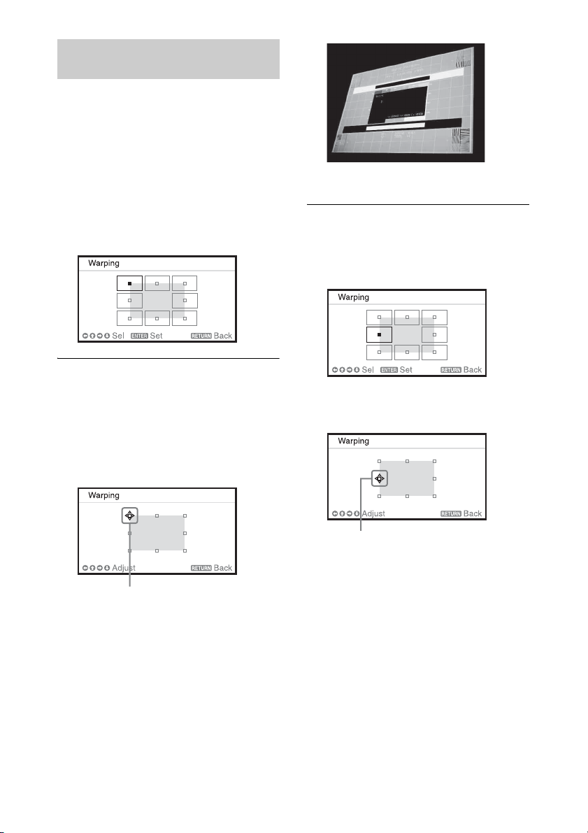
2 Select “Warping.”
The guide is displayed.
When correcting the corner(s) of
the image
1 Move x using V/v/B/b to select the
corner you want to correct.
2 Press the ENTER key.
The cursor appears.
3 Adjust the position of the corner you
want to correct, using V/v/B/b.
Press the RESET key to restore the
projected image before adjustment.
*1
When correcting deflection on the
left/right sides of the image
1 Move x using V/v/B/b to select the
side you want to correct.
2 Press the ENTER key.
The cursor appears.
3 Adjust the deflection of the side, using
V/v/B/b.
You can adjust the center point of
deflection using V/v. For the range of
deflection, use B/b. You can adjust the
left/right side independently.
Correcting Image Twist (Warp
Correction Feature)
Adjust using this cursor
Adjust using this cursor
21
Press the RESET key to restore the
projected image before adjustment.
*1
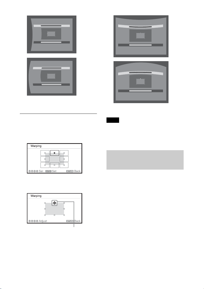
When correcting deflection on the
top/bottom sides of the image
1 Move x using V/v/B/b to select the
side you want to correct.
2 Press the ENTER key.
The cursor appears.
3 Adjust the deflection of the side, using
V/v/B/b.
You can adjust the center point of
deflection using B/b. For the range of
deflection, use V/v. You can adjust the
top/bottom independently.
Press the RESET key to restore the
projected image before adjustment.
*1
*1: The setting may not be reset depending on
the combination of adjustment values of
the Screen Fitting setting items. In this
case, reset all of the Screen Fitting setting
items.
1 Install the projectors.
Input a pattern, etc., to adjust the
projected positions from multiple
projectors.
2 Set the ID mode.
Set a different ID mode for each
projector (page 31).
3 Set the picture mode.
Set the picture mode of the multiple
projectors to “Multi Screen” (page 24).
4 Unify the color space.
Set the color space of the multiple
projectors to the same mode (Custom 1
to 3) (page 35). R/G/B can be finely
adjusted as necessary.
Adjust using this cursor
Note
Blending Projections from
Multiple Projectors on a
Screen
 Loading...