


 Loading...
4-575-751-02 (1)
Data
Projector
Operating Instructions
Before operating the unit, please read this manual thoroughly and retain it for future reference.
VPL-EX293/EX253/EX233
Not all models are available in all countries and area. Please check with your local Sony Authorized Dealer.
© 2015 Sony Corporation
WARNING
To reduce the risk of fire or electric shock, do not expose this apparatus to rain or moisture.
To avoid electrical shock, do not open the cabinet. Refer servicing to qualified personnel only.
WARNING
THIS APPARATUS MUST BE EARTHED.
WARNING
When installing the unit, incorporate a readily accessible disconnect device in the fixed wiring, or connect the power plug to an easily accessible socket-outlet near the unit. If a fault should occur during operation of the unit, operate the disconnect device to switch the power supply off, or disconnect the power plug.
WARNING:
1Use the approved Power Cord (3-core mains lead) / Appliance Connector / Plug with earthing-contacts that conforms to the safety regulations of each country if applicable.
2Use the Power Cord (3-core mains lead) / Appliance Connector / Plug conforming to the proper ratings (Voltage, Ampere).
If you have questions on the use of the above Power Cord / Appliance Connector / Plug, please consult a qualified service personnel.
IMPORTANT
The nameplate is located on the bottom.
For the customers in Taiwan only
For the customers in the U.S.A. SONY LIMITED WARRANTY - Please visit http://www.sony.com/psa/warranty for important information and complete terms and conditions of Sony’s limited warranty applicable to this product.
For the customers in Canada SONY LIMITED WARRANTY - Please visit http://www.sonybiz.ca/pro/lang/en/ ca/article/resources-warranty-product- registration for important information and complete terms and conditions of Sony’s limited warranty applicable to this product.
For the customers in Europe
Sony Professional Solutions Europe - Standard Warranty and Exceptions on Standard Warranty.
Please visit http://www.pro.sony.eu/ warranty for important information and complete terms and conditions.
For the customers in Korea
SONY LIMITED WARRANTY - Please visit http://bpeng.sony.co.kr/handler/ BPAS-Start for important information and complete terms and conditions of Sony’s limited warranty applicable to this product.
2

Table of Contents |
|
Precautions ......................................... |
5 |
On safety ....................................... |
5 |
Safety precautions for installing the |
|
unit on a ceiling ......................... |
6 |
On Installation .............................. |
6 |
On cleaning the lens and the |
|
cabinet ....................................... |
7 |
On Illumination ............................ |
7 |
On Screen ..................................... |
7 |
On Fan .......................................... |
7 |
On Lamp ....................................... |
7 |
For carrying .................................. |
8 |
On LCD Projector ........................ |
8 |
On Condensation .......................... |
8 |
Notes on security .......................... |
8 |
Checking the Supplied Accessories ... |
9 |
Installing Projector Station for |
|
Network Presentation ................ |
9 |
Installing Batteries ........................ |
9 |
Selecting the Menu Language .......... |
10 |
Overview |
|
Location and Function of |
|
Controls ........................................ |
11 |
Main Unit ................................... |
11 |
Terminals .................................... |
12 |
Remote Commander and Control |
|
Panel Keys ............................... |
13 |
Preparation |
|
Connecting the Projector .................. |
15 |
Connecting a Computer .............. |
15 |
Connecting a Video equipment .. |
17 |
Connecting a USB memory |
|
device ...................................... |
19 |
Connecting an External Monitor |
|
Equipment ............................... |
19 |
Projecting/Adjusting an |
|
Image |
|
Projecting an Image ......................... |
20 |
Adjusting the Projected image ... |
21 |
Turning Off the Power ............... |
24 |
Adjustments and Settings |
|
Using a Menu |
|
Using a MENU ................................ |
25 |
The Picture Menu ............................ |
26 |
The Screen Menu ............................. |
27 |
The Function Menu ......................... |
30 |
The Operation Menu ........................ |
31 |
The Connection/Power Menu .......... |
32 |
The Installation Menu ...................... |
34 |
The Information Menu .................... |
35 |
Network |
|
Using Network Features .................. |
36 |
Displaying the Control Window of |
|
the Projector with a Web |
|
Browser ................................... |
36 |
Confirming the Information |
|
regarding the Projector ........... |
37 |
Operating the Projector from a |
|
Computer ................................ |
38 |
Using the e-mail report |
|
Function .................................. |
38 |
Table of Contents |
3 |
|
|

Setting the LAN Network of the |
|
projector .................................. |
39 |
Setting the WLAN Network of the |
|
projector .................................. |
40 |
Setting the Custom Labels for the |
|
Input Terminals of the |
|
Projector .................................. |
42 |
Setting the Control Protocol of the |
|
Projector .................................. |
43 |
Presentation Function via |
|
Network |
|
Using Presentation Function via |
|
Network ........................................ |
46 |
Installing Projector Station for |
|
Network Presentation .............. |
46 |
Starting Projector Station for |
|
Network Presentation .............. |
46 |
Projecting an Image .................... |
47 |
Connection Settings .................... |
48 |
Using the Controller ................... |
48 |
Displaying Images or Files Sent |
|
from a Tablet |
|
PC/Smartphone ....................... |
49 |
Playing Video using USB |
|
Connection |
|
Playing Video using USB |
|
Connection .................................... |
50 |
Starting USB Display ................. |
50 |
Playing Video ............................. |
50 |
Using the Controller ................... |
50 |
USB Media Viewer |
|
Using USB Media Viewer ................ |
52 |
Thumbnail Mode ........................ |
53 |
Option Menu ............................... |
53 |
Display Mode ............................. |
54 |
Option Menu .............................. |
54 |
Slideshow Mode ......................... |
54 |
Option Menu .............................. |
55 |
Others |
|
Indicators ......................................... |
56 |
Messages List .................................. |
57 |
Troubleshooting ............................... |
58 |
Replacing the Lamp ......................... |
60 |
Cleaning the Air Filter ..................... |
62 |
Specifications ................................... |
63 |
Projection Distance .......................... |
68 |
Dimensions ...................................... |
74 |
END USER LICENSE |
|
AGREEMENT ............................. |
78 |
Notice on GNU GPL/LGPL Applied |
|
Software ....................................... |
84 |
Index ................................................ |
94 |
4Table of Contents
Precautions
On safety
•Check that the operating voltage of your unit is identical with the voltage of your local power supply. If voltage adaptation is required, consult with qualified Sony personnel.
•Should any liquid or solid object fall into the cabinet, unplug the unit and have it checked by qualified Sony personnel before operating it further.
•Unplug the unit from the wall outlet if it is not to be used for several days.
•To disconnect the cord, pull it out by the plug. Never pull the cord itself.
•The wall outlet should be near the unit and easily accessible.
•The unit is not disconnected from the AC power source (mains) as long as it is connected to the wall outlet, even if the unit itself has been turned off.
•Do not look into the lens while the lamp is on.
•Do not place your hand or objects near the ventilation holes — the air coming out is hot.
•Be careful not to catch your fingers by the front feet (adjustable) when you adjust the height of the unit. Do not push hard on the top of the unit with the front feet (adjustable) out.
•Avoid using an extension cord with a low voltage limited since it may cause the short-circuit and physical incidents.
•Do not catch your finger between the unit and surface of the floor when moving the projector installed on the floor.
•Do not move the projector when it is turned on and the cabinet cover is open.
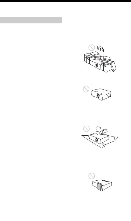
•Do not install the unit in a location near heat sources such as radiators or air ducts, or in a place subject to direct sunlight, excessive dust or humidity, mechanical vibration or shock.
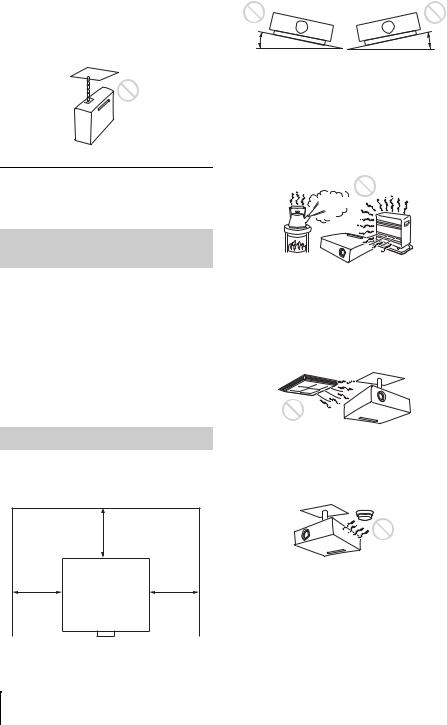
•Never mount the projector on the ceiling or move it by yourself. Be sure to consult with qualified Sony personnel (charged).
•If the ventilation holes are blocked, internal heat builds up, and it may cause a fire or damage the unit. To allow adequate air circulation and prevent internal heat build-up, follow the items below:
•Leave space around the unit (page 6).
•Avoid using something to cover the ventilation holes (exhaust/intake).
•Do not place the unit on surfaces such as an original packing sheet, soft cloth, papers, rugs, or scraps of paper. The ventilation holes may take in such materials.
•Do not place any object just in front of the lens that may block the light during projection. Heat from the light may damage the object. Use the picture muting function to cut off the picture.
Precautions 5
•Do not use the Security bar for the purpose of preventing theft for transporting or installing the unit. If you lift the unit by the Security bar or hang the unit by this bar, it may cause the unit to fall and be damaged, and may result in personal injury.
For dealers
•Be sure to secure the cabinet cover firmly when installing to the ceiling firmly.
Safety precautions for installing the unit on a ceiling
•Never mount the projector on the ceiling or move it by yourself. Be sure to consult the store where you purchased the projector or a dedicated installer.
•When installing the unit on a ceiling, be sure to use a safety wire, etc., to prevent the unit from falling. For the installation, be sure to consult the store where you purchased the projector or a dedicated installer.
On Installation
•When installing the unit, leave space between any walls, etc. and the unit as illustrated.
|
More than 30 cm |
|
(11 7/8 inches) |
More than |
More than |
30 cm |
30 cm |
(11 7/8 |
(11 7/8 |
inches) |
inches) |
•Avoid using if the unit is tilted more than 15 degrees horizontally.
15° |
15° |
•Install the projector on the floor or ceiling. Any other installation causes a malfunction such as color irregularity or shortening lamp life.
•Avoid using the unit in a location where the temperature or humidity is very high, or temperature is very low.
•Avoid installing the unit in a location subject to direct cool or warm air from an air-conditioner. Installing in such a location may cause malfunction of the unit due to moisture condensation or rise in temperature.
•Avoid installing the unit in a location near a heat or smoke sensor. Installing in such a location may cause malfunction of the sensor.
•Avoid installing the unit in a very dusty or extremely smoky environment. Otherwise, the air filter will become obstructed, and this may cause a malfunction of the unit or damage it.
6Precautions

•When using the unit at an altitude of 1,500 m or higher, set “High Altitude Mode” to “On” in the Installation menu. Failing to set this mode when using the unit at high altitudes could have adverse effects, such as reducing the reliability of certain components.
•Set “Installation Attitude” on the Installation menu correctly to suit to the Installation angle. Continuing to use the wrong setting may affect component reliability.
On cleaning the lens and the cabinet
•Be sure to disconnect the AC power cord from the AC outlet before cleaning.
•If you rub on the unit with a stained cloth, the cabinet may be scratched.
•If the unit is exposed to volatile materials such as insecticide, or the unit is in contact with a rubber or vinyl resin product for a long period of time, the unit may deteriorate or the coating may come off.
•Do not touch the lens with bare hands.
•On cleaning the lens surface:
Wipe the lens gently with a soft cloth, such as a glass cleaning cloth. Stubborn stains may be removed with a soft cloth lightly dampened with water. Never use solvent such as alcohol, benzene or thinner, or acid, alkaline or abrasive detergent, or a chemical cleaning cloth.
•On cleaning the cabinet:
Clean the cabinet gently with a soft cloth. Stubborn stains may be removed with a soft cloth lightly dampened with mild detergent solution and wrung, followed by wiping with a soft dry cloth. Never use solvent such as alcohol, benzene or thinner, or acid, alkaline or abrasive detergent, or a chemical cleaning cloth.
On Illumination
To obtain the best picture, the front of the screen should not be exposed to direct lighting or sunlight.
On Screen
When using a screen with an uneven surface, stripes pattern may rarely appear on the screen depending on the distance between the screen and the unit or the zooming magnifications. This is not a malfunction of the unit.
On Fan
Since the projector is equipped with fans inside to prevent internal temperature from rising, there may be some noise. This is a normal result of the manufacturing process and does not indicate a malfunction. If, however, in a case of abnormal noise, consult with qualified Sony personnel.
On Lamp
The lamp used as a light source contains mercury that has high internal pressure. A high-pressure mercury lamp has the following characteristics:
•Brightness of the lamp will be lowered as the elapse of time used.
•The lamp may break with a loud noise as a result of shock, damage, or deterioration caused by the elapse of time. The lamp may become unlit and may burn out.
•The lamp life varies with individual differences or usage conditions of each lamp. Therefore, it may break or will not light even before the specified replacement time.
•It may possibly break after the replacement time has elapsed. Replace the lamp with a new one as soon as possible if a message displayed on the projected image, even if the lamp normally lights.
Precautions 7

For carrying
This unit is precision equipment. When carrying the unit, do not subject the unit to shocks, or fall. It may damage the unit.
On LCD Projector
The LCD projector is manufactured using high-precision technology. You may, however, see tiny black points and/or bright points (red, blue, or green) that continuously appear on the LCD projector. This is a normal result of the manufacturing process and does not indicate a malfunction.
Also, when you use multiple LCD projectors to project onto a screen, even if they are of the same model, the color reproduction among projectors may vary, since color balance may be set differently from one projector to the next.
On Condensation
If the room temperature where the projector is installed changes rapidly, or if the projector is moved suddenly from a cold to a warm place, condensation in the projector may occur. As the condensation may cause malfunction, be careful in adjusting temperature settings of the air conditioner. If condensation occurs, leave the projector turned on for about two hours before use.
Notes on security
•SONY WILL NOT BE LIABLE FOR DAMAGES OF ANY KIND RESULTING FROM A FAILURE TO IMPLEMENT PROPER SECURITY MEASURES ON TRANSMISSION DEVICES, UNAVOIDABLE DATA LEAKS RESULTING FROM TRANSMISSION SPECIFICATIONS, OR SECURITY PROBLEMS OF ANY KIND.
•Depending on the operating environment, unauthorized third parties on the network may be able to access the unit. When connecting the unit to the network, be sure
to confirm that the network is protected securely.
•Communication content may be unknowingly intercepted by unauthorized third parties in the vicinity of the signals. When using wireless LAN communication, implement security measures properly to protect the communication content.
•From a safety standpoint, when using the unit connected with the network, it is strongly recommended to access the Control window via a Web browser and change the access limitation settings from the factory preset values (refer to “Using Network Features” (page 36)). Changing the password regularly is also recommended.
•Do not browse any other website in the Web browser while making settings or after making settings. Since the login status remains in the Web browser, close the Web browser when you complete the settings to prevent unauthorized third parties from using the unit or harmful programs from running.
Notes
•Always verify that the unit is operating properly before use. SONY WILL NOT BE LIABLE FOR DAMAGES OF ANY KIND INCLUDING, BUT NOT LIMITED TO, COMPENSATION OR REIMBURSEMENT ON ACCOUNT OF THE LOSS OF PRESENT OR PROSPECTIVE PROFITS DUE TO FAILURE OF THIS UNIT, EITHER DURING THE WARRANTY PERIOD OR AFTER EXPIRATION OF THE WARRANTY, OR FOR ANY OTHER REASON WHATSOEVER.
•SONY WILL NOT BE LIABLE FOR CLAIMS OF ANY KIND MADE BY USERS OF THIS UNIT OR MADE BY THIRD PARTIES.
•SONY WILL NOT BE LIABLE FOR THE TERMINATION OR DISCONTINUATION OF ANY SERVICES RELATED TO THIS UNIT THAT MAY RESULT DUE TO CIRCUMSTANCES OF ANY KIND.
8Precautions
Checking the Supplied Accessories
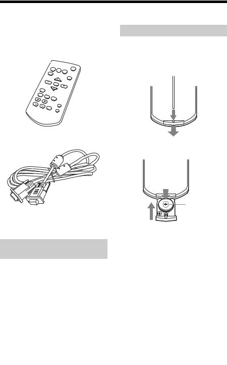
RM-PJ8 Remote Commander (1) Lithium battery (CR2025) (1)
The battery is already installed. Before using the remote commander, remove the insulation film.
Installing Batteries
1 Pull out the lithium battery compartment.
Pull out the battery compartment with a stick as shown in the illustration.
AC power cord (1) Mini D-sub 15 pin cable (1.8 m) (1)
2 Insert a lithium battery.
Operating Instructions (this manual) (1) Projector Station for Network Presentation application (CD-ROM) (1)
Installing Projector Station for Network Presentation
1 Close all running applications.
2 Insert the supplied CD-ROM into the CD-ROM drive of the computer.
3 Open the CD-ROM and double-click the .exe file.
When the message “User Account Control” is displayed, click “Allow” or “Yes.”
4 Follow the on-screen instructions to install the software.
With the 3 (plus) side facing up.
3 Close the lithium battery compartment.
CAUTION
Danger of explosion if battery is incorrectly replaced.
Replace only with the same or equivalent type recommended by the manufacturer. When you dispose of the battery, you must obey the law in the relative area or country.
Installing batteries
One lithium battery (CR2025) is supplied for the RM-PJ8 Remote Commander. To avoid risk of explosion, use a lithium battery (CR2025).
Checking the Supplied Accessories |
9 |
|
|

Selecting the Menu Language
The factory setting for the language for displaying menus, messages, etc. is English. To change the on-screen language, proceed as follows:
3
MENU
2
1 Plug in the AC power cord into a wall outlet.
2 Turn on the projector. Press the ?/1 key.
3 Press the MENU key to display the menu.
If the display cannot be properly seen, adjust the focus, size, and position of the projected image (page 21).
4 Select the menu language.
1Press the V or V key to select the Operation ( ) menu then press the ENTER key.
2Press the V or V key to select
“Language (  )” then press the ENTER key.
|
1 |
|
Operation |
|
|
|
Language |
English |
|
Status |
OnStatus OnStatus |
|
Security Lock |
Off |
|
Control Key Lock |
Off |
S e l |
S e t |
B a ck |
3Press the V/V/B/B key to select a language, then press the ENTER key.
5 Press the MENU key to turn off the menu screen.
10 Selecting the Menu Language
B Overview
Location and Function of Controls
Main Unit
6
1
5 |
2 |
|
4 |
||
|
||
|
3 |
|
7 |
|
|
8 |
|
|
|
7 |
|
QA |
8 |
|
0 |
9 |
QG |
QS |
QD
QF
K Ventilation holes (exhaust)
Caution
Do not place anything near the ventilation holes as this may cause internal heat buildup. Do not place your hand near the ventilation holes and the circumference as this may cause injury.
LTerminals (page 12)
MSecurity bar
Connects to a commercially available security chain or wire.
NSecurity lock
Connects to an optional security cable manufactured by Kensington.
For details, visit Kensington’s web site. http://www.kensington.com/
OControl panel keys (page 13)
Overview
AFocus ring (page 21)
BZoom ring (page 21)
CLens
DRemote Control Receiver
EON/STANDBY indicator (page 56)
FLAMP/COVER indicator (page 56)
GFront feet (adjustable) (page 22)
HFoot adjust button (page 22)
IAir filter cover/Ventilation holes (intake) (page 62)
JLamp cover (page 60)
Location and Function of Controls |
11 |
|
|

Terminals
4 5 1 QA 3 8 Q;
6

7

2 9
Input (pages 15, 17)
AINPUT A
Video: RGB/YPBPR input terminal (RGB/YPBPR)
BINPUT B
Video: RGB input terminal (RGB)
CINPUT C
Video: HDMI input terminal (HDMI)
DS VIDEO (S VIDEO IN)
Video: S video input terminal (S VIDEO IN)
EVIDEO (VIDEO IN)
Video: Video input terminal (VIDEO)
Output (page 19)
FOUTPUT
Video: Monitor output terminal (MONITOR)
Note
H LAN terminal (page 36)
Caution
For safety, do not connect the terminal for peripheral device wiring that might have excessive voltage to this port.
Follow the instructions for this port.
IAC IN ( ) socket
Connects the supplied AC power cord.
JUSB terminal (Type A) ( ) (pages 19, 52)
KUSB terminal (Type B) ( ) (page 50)
This terminal outputs the projected image only when INPUT A or INPUT B is used.
Others
GRS-232C terminal (RS-232C)
RS-232C compatible control terminal. Connects the computer’s RS-232C terminal and the RS-232C cross cables.
12 Location and Function of Controls
Remote Commander and Control Panel Keys
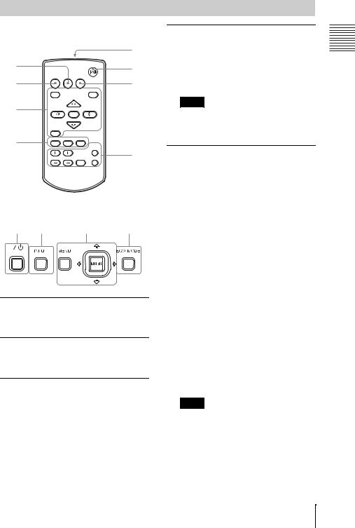
Remote Commander
|
|
|
|
|
7 |
4 |
|
|
|
|
1 |
|
|
|
|
|
|
|
INPUT |
APA |
ECO MODE |
|
6 |
2 |
|
|
|
|
|
|
MENU |
|
|
RESET |
|
3 |
|
ENTER |
|
|
|
|
|
|
|
||
|
RETURN |
|
|
|
|
4 |
ASPECT |
KEYSTONE |
PATTERN |
|
|
|
|
|
BLANK |
|
|
|
|
|
|
|
|
|
D ZOOM |
VOLUME |
FREEZE |
MUTING |
5 |
Control Panel Keys
1 |
2 |
3 |
6 |
ATurning on the power/Going to standby mode
?/1 (On/Standby) key
BSelecting an input signal (page 20)
INPUT key
COperating a menu (page 25)
MENU key RESET key
ENTER /V/V/B/B (arrow) keys
RETURN key
DAdjusting the image (page 21)
ASPECT key (page 27) KEYSTONE key (page 23) PATTERN key (page 23)
APA (Auto Pixel Alignment) key* (page 23)
Note
*Use this key when inputting a computer signal via the RGB input terminal (INPUT A or INPUT B).
EUsing various functions during projecting
D ZOOM (Digital Zoom) +/– key*1
Enlarges a portion of the image while projecting.
1Press the D ZOOM + key to display the digital zoom icon on the projected image.
2Press the V/V/B/B keys to move the digital zoom icon to the point on the image you want to enlarge.
3Press the D ZOOM + key or the D ZOOM – key repeatedly to change the
enlargement ratio. The image can be enlarged up to 4 times.
Press the RESET key to restore the previous image.
BLANK key
Cuts off the projected image temporarily. Press again to restore the previous image. Picture muting helps reduce power consumption.
FREEZE key*2
Pauses a projected image. Press again to restore the image.
Notes
*1: Use this key when inputting a computer signal. But it may not be used depending on the resolution of the input signal.
*2: Use this key when inputting a computer signal.You cannot use this key when “Type A USB”, “Type B USB” or “Network” is selected as the input.
Location and Function of Controls
Overview
13
FSetting the energy–saving mode easily
ECO MODE key
Energy-saving mode can be set easily. Energy-saving mode consists of “Lamp Mode,” “With No Input,” “With Static Signal” and “Standby Mode.”
1Press the ECO MODE key to display the ECO Mode menu.
ECO Mode
ECO
User
: S e l |
RETURN : B a ck |
2Press the V/V key or ECO MODE key to select “ECO” or “User” mode. ECO: Sets each mode to the optimum
energy-saving value. Lamp Mode: Low With No Input: Standby
With Static Signal: Lamp Dimming
Standby Mode: Low
User: Sets each item of the ECO Mode menu as you desire (go to step 3).
3Select “User” then press the B key. The setting items appear.
USer
Lamp Mode |
|
HiGh |
ConStAnt BrightneSS |
ON |
|
AUto Power SAving |
|
|
With No InpUt |
Off |
|
With StAtic SignAl |
LAmp Dimming |
|
StAndBy Mode |
|
StAndArd |
: S e l |
: S e t |
RETURN : B A ck |
4Press the V/V key to select the item then press the ENTER key.
5Press the V/V key to select the setting value.
6Press the ENTER key.
The screen returns to the User screen.
For details on ECO Mode settings, see “Lamp Mode,” “With No Input,” “With Static Signal” and “Standby Mode” on the Connection/Power menu (page 32).
Note
If you set “ECO Mode” to “ECO,” or “Standby Mode”(in “User”) to “Low,” the network control function will be disabled in standby mode. If the external control is being performed by using the network or network control function, do not select “ECO,” or do not set “Standby Mode” ( in “User”) to “Low.”
Others
G Infrared transmitter
About remote commander operation
•Direct the remote commander toward the remote control detector.
•The shorter the distance between the remote commander and the projector is, the wider the angle within which the remote commander can control the projector becomes.
•Make sure that nothing obstructs the infrared beam between the remote commander and the remote control detector on the projector.
14 Location and Function of Controls

B Preparation
Connecting the Projector
Notes
•Make sure all the equipment is powered off when connecting the projector.
•Use the proper cables for each connection.
•Insert the cable plugs firmly; Loose connections may reduce performance of picture signals or
cause a malfunction. When pulling out a cable, be sure to grip it by the plug, not the cable itself.
• For more information, refer also to the instruction manuals of the equipment you are connecting.
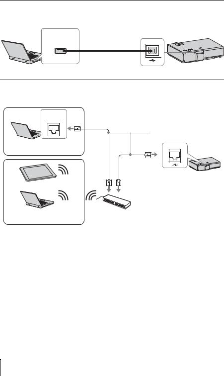
Connecting a Computer
Connection with a computer is explained for each input signal.
INPUT A/INPUT B
For connecting a computer with an RGB output terminal.
Mini D-sub 15-pin cable (supplied)
RGB output terminal
Computer
Note
It is recommended that you set the resolution of your computer to 1024 × 768 pixels for the external monitor.
INPUT C
For connecting a computer with an HDMI output terminal.
HDMI cable (not supplied)
HDMI output terminal
Computer
Notes
•Use HDMI-compatible equipment which has the HDMI Logo.
•Use a high speed HDMI cable(s) on which the cable type logo is specified. (Sony products are recommended.)
•The HDMI terminal of this projector is not compatible with DSD (Direct Stream Digital) Signal or CEC (Consumer Electronics Control) Signal.
Preparation
Connecting the Projector |
15 |
|
|
USB terminal (Type B) (  )
)
For connecting to a computer with a USB terminal (“Playing Video using USB Connection” (page 50)).
USB terminal
(Type A) USB A-B cable (not supplied)
Computer
LAN terminal
For connecting to a computer, tablet PC, or smartphone via a hub or router (“Presentation Function via Network” (page 46)).
LAN terminal
LAN cable (straight type)

 (not supplied) Computer
Wired connection
Tablet PC/Smartphone
Computer |
Hub, router (wireless), etc. |
|
|
Wireless connection |
|
16 Connecting the Projector
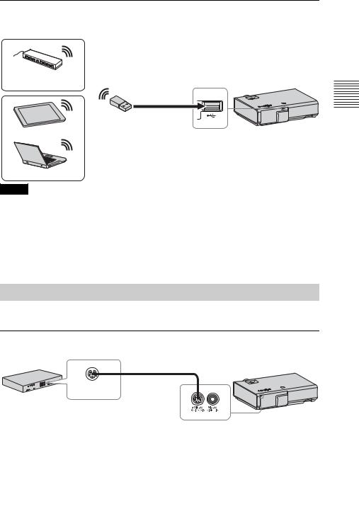
USB terminal (Type A) (  )
)
For connecting a USB wireless LAN module IFU-WLM3 (not supplied) (“Presentation Function via Network” (page 46)).
Wireless router, access point
USB wireless LAN module
IFU-WLM3 (not supplied)
Tablet PC/Smartphone
Computer
Notes
•Undesignated USB wireless LAN modules do not work.
•When connecting/disconnecting the USB wireless LAN module, make sure that the projector is in Standby mode (Standby Mode: “Low”), or the AC power cord is unplugged from the wall outlet.
•When wirelessly connecting a tablet PC/smartphone to the projector via USB wireless LAN Module IFU-WLM3 (not supplied), set “WLAN Network” to “Access Pt. (Manual)” in the projector’s “WLAN Settings” (page 32).
•For connecting to the access point, access to the Web browser, and input the settings for the access point to connect. For details, see “Setting the WLAN Network of the projector” (page 40).
Connecting a Video equipment
Connections with a VHS video deck, DVD player, or BD player are explained for each input signal.
S VIDEO IN
For connecting video equipment with an S-video output terminal.
S video cable (not supplied)
S video output
terminal
Computer
Preparation
Connecting the Projector |
17 |
|
|
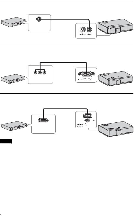
VIDEO IN
For connecting video equipment with a video output terminal.
Video cable (not supplied)
Video output
terminal
Video equipment
INPUT A
For connecting video equipment with a YPBPR output terminal.
Component – Mini D-sub 15-pin cable (not supplied)
YPBPR output terminal
Video equipment
INPUT C
For connecting video equipment with an HDMI output terminal.
HDMI cable (not supplied)
HDMI output terminal
Video equipment
Notes
•Use HDMI-compatible equipment which has the HDMI Logo.
•Use a high speed HDMI cable(s) on which the cable type logo is specified. (Sony products are recommended.)
•The HDMI terminal of this projector is not compatible with DSD (Direct Stream Digital) Signal or CEC (Consumer Electronics Control) Signal.
18 Connecting the Projector
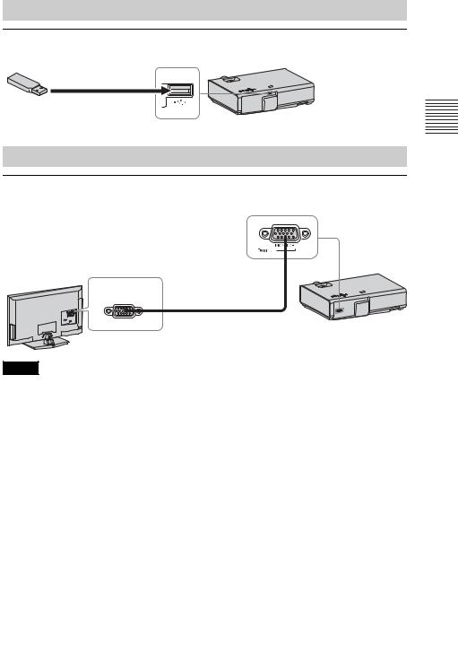
Connecting a USB memory device
USB terminal (Type A) (  )
)
For connecting a USB memory device (“Using USB Media Viewer” (page 52)).
USB memory device (not supplied)
Connecting an External Monitor Equipment
OUTPUT
Projected images can be output to display equipment such as a monitor equipment.
Display equipment
RGB input terminal
Mini D-sub 15-pin cable (supplied)
Note
Projected images can be output.
Preparation
Connecting the Projector |
19 |
|
|
B Projecting/Adjusting an Image
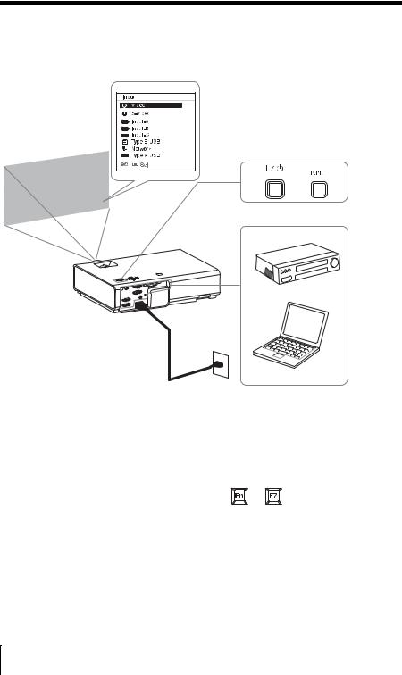
Projecting an Image
The size of a projected image depends on the distance between the projector and screen. Install the projector so that the projected image fits the screen size. For details on projection distances and projected image sizes, see “Projection Distance” (page 68).
3 5
|
|
4 |
|
2 |
|
|
|
Video equipment |
Projector |
|
|
1 |
Wall outlet |
6 |
|
|
Computer |
1 Plug the AC power cord into the wall outlet.
2 Connect all equipment to the projector (page 15).
3 Press the ?/1 key to turn on the unit.
4 Turn on the connected equipment.
5 Select the input source.
Press the INPUT key on the projector to display the menu for switching input signal on the screen. Press the INPUT key repeatedly, or press the V/V key to select an image to be projected.
6 When projecting a computer image, switch your computer’s output to external display.
The method to switch the output varies depending on the type of computer.
(Example)
+
To project image files stored in a USB memory device, see “USB Media Viewer” (page 52). To play video using USB Connection, see “Playing Video using USB Connection” (page 50). To use Presentation Function via Network, see “Presentation Function via Network” (page 46).
20 Projecting an Image
7 Adjust the focus, size and position of the projected image (page 21).
Adjusting the Projected image |
|
|
|
Focus |
Size (Zoom) |
Position |
|
Focus ring |
|
Foot |
anProjecting/Adjusting |
|
|
||
|
|
|
|
|
|
adjust |
|
|
|
button |
|
|
Zoom ring |
Front feet |
Image |
|
(adjustable) |
||
|
|
||
|
|
|
|
Projecting an Image 21
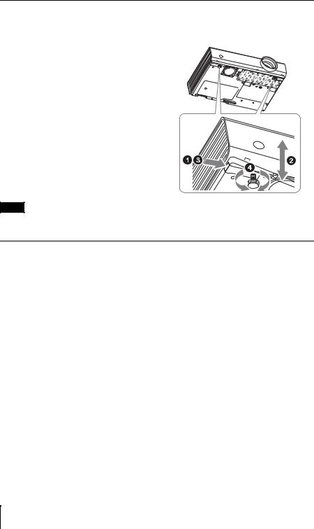
Adjusting the tilt of the projector with the front feet (adjustable)
By changing the tilt of the projector with the foot adjust buttons/front feet (adjustable), you can adjust the position of the projected image.
How to adjust the angle
1 Press and hold the foot adjust buttons.
2 Lift up the front of the projector to adjust the angle.
3Release the foot adjust buttons.
4Turn the front feet (adjustable) to set the angle of the projector precisely.
Notes
•Be careful not to let the projector down on your fingers.
•Do not push hard on the top of the projector with the front feet (adjustable) extended.
Changing the aspect ratio of the projected image
Press the ASPECT key on the remote commander to change the aspect ratio of the projected image. You can also change the setting in Aspect of the Screen menu (pages 27).
22 Projecting an Image
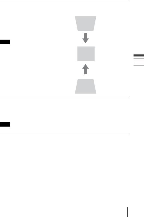
Correcting trapezoidal distortion of the projected image (Keystone feature)
Normally the Keystone feature automatically adjusts the projected image. The Keystone feature may not work automatically if the screen is tilted. In this case, set Keystone manually.
1Press the KEYSTONE key on the remote commander or select V Keystone in the Installation menu.
2Use the V/V/B/B keys to set the value. The higher the value, narrower the top of the projected image. The lower the value, the narrower the bottom.
Note
Increase the number towards plus
Since the Keystone adjustment is an electronic correction, the image may be deteriorated.
Increase the number towards minus
Displaying a pattern
You can display a pattern for adjusting the projected image or a grid pattern with the PATTERN key on the remote commander. Press the PATTERN key again to restore the previous image. You can use a grid pattern as a guide to write text or to draw lines and shapes on the whiteboard or blackboard without using a computer.
Note
You cannot use this key when “Type A USB”, “Type B USB” or “Network” is selected as the input.
Automatically adjusts Phase, Pitch and Shift of projected image while a signal is input from a computer (APA (Auto Pixel Alignment))
Press the APA key on the remote commander. Press again to cancel adjusting during the setting. You can also set APA in the Screen Menu (page 27). If Smart APA in the Function menu is set to “On”, executes APA automatically when a signal is input (page 30).
Image an Projecting/Adjusting
Projecting an Image 23
Turning Off the Power
1 Press the ?/1 key on the unit or the remote commander.
The projector starts shutdown and turns off. If you press the ?/1 key within 10 seconds again, shutdown is cancelled.
Note
Do not turn off the projector soon after the lamp lights. It may cause a malfunction of the lamp (does not light ,etc.).
2 Unplug the AC power cord from the wall outlet.
To turn off without displaying confirmation message
Press and hold the ?/1 key on the unit for a few seconds (page 57).
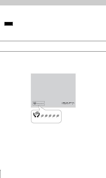
ECO gauge
This gauge indicates the current effectiveness of the projector’s ECO function. (For details on the ECO function, see “ECO MODE key” (page 14) and “ECO” (page 32).)
The leaf icons are displayed when the projector is shut down. The number of displayed icons varies according to how much energy is saved as a result of using the ECO function.
ECO gauge
24 Projecting an Image
B Adjustments and Settings Using a Menu
Using a MENU
Note
The menu displays used for the explanation below may be different depending on the model you are using.
1 Press the MENU key to display the menu.
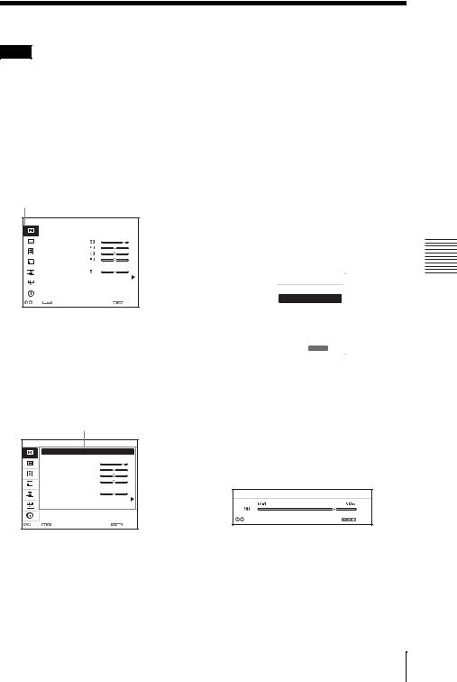
2 Select the setting menu.
Use the V/V key to select the setting menu then press the B key or ENTER key.
Setting menu
PictUre
|
|
|
|
|
PictUre Mode |
StAndArd |
|
|
|
|
|
ReSet |
|
|
|
|
|
|
ContrASt |
|
|
|
|
|
|
BrightneSS |
|
|
|
|
|
|
|
|
|
|
|
|
|
Color |
|
|
|
|
|
|
HUe |
|
|
|
|
|
|
Color Temp. |
Low |
|
|
|
|
|
ShArpneSS |
|
|
|
|
|
|
Expert Setting |
|
|
|
|
|
|
|
|
|
|
|
|
|
|
|
|
|
|
|
|
|
|
|
|
: S e l |
: S e t |
: B A ck |
||
3 Select the setting item.
Use the V/V key to select the setting menu then press the B key or ENTER key.
To return to the selection screen of the setting menu, press the B or RETURN key.
Setting items
PictUre
|
PictUre Mode |
StAndArd |
|
ReSet |
|
|
ContrASt |
80 |
|
BrightneSS |
50 |
|
Color |
50 |
|
HUe |
50 |
|
Color Temp. |
Low |
|
ShArpneSS |
5 |
|
Expert Setting |
|
: S e l |
: S e t |
: B A ck |
operations in step 3 and then press the ENTER key to register the setting.
To return to the selection screen of the setting items, press the B or RETURN key. You can press the RESET key to reset an item to its factory setting value to aid setting.
Using a pop-up menu
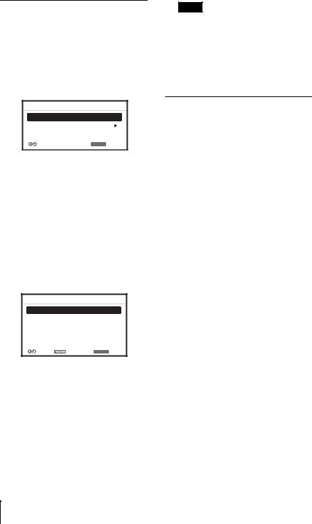
Press the V/V/B/B key to select an item. A selected item takes effect immediately, except “Language”, which will take effect after you press the ENTER key.
PictUre Mode
DynAmic
StAndArd
PreSentAtion
BlAckBoArd
WhiteBoArd
CinemA
 :Sel RETURN :BAck
Using the setting menu
Press the V/V key to select the item. Press the ENTER key to register the setting and return to the previous screen.
Using the adjustment menu
To increase the value, press the V/B key and to decrease the number, press the V/B key. Press the ENTER key to register the setting and return to the previous screen.
ContrASt
AdjUSt |
BAck |
4 Make the setting or adjustment for the selected item.
The setting method varies, depending on the setting item.
If the next menu window is displayed, select the item according to the
5 Press the MENU key to clear the menu.
The menu disappears automatically if no operation is performed.
Menu a Using Settings and Adjustments
Using a MENU 25

 The Picture Menu
The Picture is used to adjust the picture for each input signal.
Items |
Item descriptions |
|
|
|
|
Picture Mode |
Dynamic: Emphasizes the contrast to produce a dynamic and vivid picture. |
|
|
|
Standard: Provides an image which is natural and well balanced. |
|
|
Presentation: Provides a bright image, suitable for presentations. |
|
|
Blackboard: Provides an image suitable for displaying on a blackboard. |
|
|
Whiteboard: Provides an image suitable for displaying on a whiteboard. |
|
|
Cinema: Provides an image suitable for viewing movies. |
|
|
|
Reset*1 |
Resets the factory setting. |
|
Contrast |
The higher the value, the greater the contrast. The lower the value, the lower |
|
|
|
the contrast. |
|
|
|
Brightness |
The higher the value, the brighter the picture. The lower the value, the darker |
|
|
|
the picture. |
|
|
|
Color*2 *3 |
The higher the value, the greater the intensity. The lower the value, the lower |
|
|
|
the intensity. |
|
|
|
Hue*2 *3 *4 |
The higher the value, the more greenish the picture becomes. The lower the |
|
|
|
value, the more reddish the picture becomes. |
|
|
|
Color Temp.*5 |
High/Middle/Low: The higher the value, the more bluish the picture. The |
|
|
|
lower the value, the more reddish the picture. |
|
|
|
Sharpness*6 |
The higher the value, the sharper the picture. The lower the value, the softer |
|
|
|
the picture. |
|
|
|
Expert Setting |
|
|
|
|
|
|
Gamma |
Graphics1: Gamma correction to make halftones brighter. This setting is |
|
Mode*7 |
suitable when projecting highly colorful images, such as photos, in a bright |
|
|
place. |
|
|
Graphics2: Gamma correction to improve the reproduction of halftones. |
|
|
Highly colorful images, such as photos, can be reproduced in natural tones. |
|
|
Graphics3: Selects gamma correction to emphasize bright parts. Projects |
|
|
images explicitly. |
|
|
|
Notes
*1: The settings in the Picture return to their factory defaults, except for Picture Mode. *2: When a video signal is input, this option is available.
*3: When the signal without color burst signal is input after selecting “Video” or “S-Video”, this option is unavailable.
*4: When an analog TV signal is input, this option may not available, depending on the color system. *5: When “Picture Mode” is set to the item other than “Presentation” or “Blackboard,” this option
is available.
*6: Not available if “Input” is set to “Type A USB.”
*7: When “Picture Mode” is set to “Blackboard,” this option is unavailable.
26 The Picture Menu

 The Screen Menu
The Screen menu is used to adjust the size, position and aspect ratio of the projected image for each input signal.
Items |
Item descriptions |
|
|
|
|
Aspect*1 |
Changes the aspect ratio of the projected image. |
|
|
When the computer |
4:3: Displays the image to fit the maximum projected image size |
|
signal is input |
with an aspect ratio fixed to 4:3. |
|
|
16:9: Displays the image to fit the maximum projected image size |
|
|
with an aspect ratio fixed to 16:9. |
|
|
Full 1: Displays the image to fit the maximum projected image |
|
|
size without changing the aspect ratio of the input signal. |
|
|
Normal: Displays the image on the center position of the |
|
|
projected screen without changing the resolution of the input |
|
|
signal or enlarging the image. |
|
|
|
|
When the video signal |
4:3: Displays the image to fit the maximum projected image size |
|
is input |
with an aspect ratio fixed to 4:3. |
|
|
16:9: Displays the image to fit the maximum projected image size |
|
|
with an aspect ratio fixed to 16:9. |
|
|
Zoom: Zooms the center area of a projected image. |
|
|
|
Adjust Signal |
Adjusts the image of computer signal. Use this item if the edge of |
|
|
|
the image is cut and reception is bad. |
|
|
|
|
APA*2 *3 |
Automatically adjusts the projected image to an optimum quality |
|
|
when you press the ENTER key (page 13). |
|
|
|
|
Phase*2 |
Adjusts the dot phase of the display pixel and the input signal. Set |
|
|
to the value where looks clearest. |
|
|
|
|
Pitch*2 *5 |
The higher the value, the wider the horizontal image elements |
|
|
(pitch). The lower the value, the narrower the horizontal image |
|
|
elements (pitch). |
|
|
|
|
Shift*4 |
H (Horizontal): The higher the value, the farther right the image |
|
|
is projected on the screen. The lower the value, the image farther |
|
|
left. |
|
|
V (Vertical): The higher the value, the farther up the image is |
|
|
projected on the screen. The lower the value, the image farther |
|
|
down. |
|
|
|
Notes
*1: • Note that if the projector is used for profit or for public viewing, modifying the original picture by switching to the aspect mode may constitute an infringement of the rights of authors or producers, which are legally protected.
•Depending on the input signal, setting items for aspect ratio or some other setting items cannot be set in some cases, or changing the aspect ratio setting may have no effect.
•A part of the image may be displayed in black, depending on the setting item.
*2: Available when a computer signal is input from the RGB input terminal (INPUT A/INPUT B). *3: If the projected image includes large amount of black portion around it, the APA function will not work properly and a part of the image may not be displayed on the screen and also optimum image cannot be obtained, depending on the type of input signal. In this case, adjust the “Phase,”
“Pitch,” and “Shift” items manually.
The Screen Menu
Menu a Using Settings and Adjustments
27

*4: Available when a computer or a video signal is input from the RGB/YPBPR input terminal (INPUT A).
*5: When “APA” (page 27) or “Smart APA” (page 30) is performed, the adjusted value for “Pitch” will return to its factory default. If you want to continue using the adjusted value, set “Smart APA” to “Off.”
28 The Screen Menu

Computer signal
Video signal
Input signal |
Recommended |
|||
|
setting value and |
|||
|
projected image |
|||
4:3 |
|
Full1 |
*1 |
|
|
|
|
|
|
|
|
|
|
|
|
|
|
|
|
16:9 |
|
Full1 |
*1 *2 |
|
|
|
|
|
|
|
|
|
|
|
|
|
|
|
|
|
|
|
|
16:10 |
|
Full1*1 *2 |
|
|
|
|
|
|
|
|
|
|
|
|
4:3 |
4:3*3 |
|
|
|
|
|
|
|
16:9 |
16:9*4 |
|
|
|
|
|
|
|
|
|
|
|
|
|
*1: If you select “Normal,” the image is projected in the same resolution as the input signal without changing the aspect ratio of the original image.
*2: If you select “4:3,” the image is projected to fit the projected image size, regardless of the aspect ratio of the image.
*3: Depending on the input signal, the projected image may be projected as illustrated below. In this a case, select “16:9.”
*4: Depending on the input signal, the projected image may be projected as illustrated below. In this a case, select “Zoom.”
Menu a Using Settings and Adjustments
The Screen Menu 29
Loading...