


DATA PROJECTOR
VPL-ES7 VPL-EX7 VPL-EX7IN
VPL-EX70
REMOTE COMMANDER
RM-PJ6
SERVICE MANUAL
1st Edition (Revised 2)
!
! WARNING
This manual is intended for qualified service personnel only.
To reduce the risk of electric shock, fire or injury, do not perform any servicing other than that contained in the operating instructions unless you are qualified to do so. Refer all servicing to qualified service personnel.
! WARNUNG
Die Anleitung ist nur für qualifiziertes Fachpersonal bestimmt.
Alle Wartungsarbeiten dürfen nur von qualifiziertem Fachpersonal ausgeführt werden. Um die Gefahr eines elektrischen Schlages, Feuergefahr und Verletzungen zu vermeiden, sind bei Wartungsarbeiten strikt die Angaben in der Anleitung zu befolgen. Andere als die angegeben Wartungsarbeiten dürfen nur von Personen ausgeführt werden, die eine spezielle Befähigung dazu besitzen.
! AVERTISSEMENT
Ce manual est destiné uniquement aux personnes compétentes en charge de l’entretien. Afin de réduire les risques de décharge électrique, d’incendie ou de blessure n’effectuer que les réparations indiquées dans le mode d’emploi à moins d’être qualifié pour en effectuer d’autres. Pour toute réparation faire appel à une personne compétente uniquement.
き差しできるコンセントに電源プラグを接続してくだ さい。
WARNING
When installing the unit, incorporate a readily accessible disconnect device in the fixed wiring, or connect the power cord to a socket-outlet which must be provided near the unit and easily accessible, so that the user can turn off the power in case a fault should occur.
WARNUNG
Beim Einbau des Geräts ist daher im Festkabel ein leicht zugänglicher Unterbrecher einzufügen, oder das Netzkabel muß mit einer in der Nähe des Geräts befindlichen, leicht zugänglichen Wandsteckdose verbunden werden, damit sich bei einer Funktionsstörung die Stromversorgung zum Gerät jederzeit unterbrechen läßt.
For kundene i Norge
Dette utstyret kan kobles til et IT-strømfordelingssystem.
VPL-ES7

必ず指定の電池に交換してください。
処理してください。
CAUTION
Danger of explosion if battery is incorrectly replaced. Replace only with the same or equivalent type recommended by the manufacturer.
When you dispose of the battery, you must obey the law in the relative area or country.
ATTENTION
Il y a danger d’explosion s’il y a remplacement incorrect de la batterie. Remplacer uniquement avec une batterie du même type ou d’un type équivalent recommandé par le constructeur.
Lorsque vous mettez la batterie au rebut, vous devez respecter la législation en vigueur dans le pays ou la région où vous vous trouvez.
VORSICHT
Explosionsgefahr bei Verwendung falscher Batterien. Batterien nur durch den vom Hersteller empfohlenen oder einen gleichwertigen Typ ersetzen.
Wenn Sie die Batterie entsorgen, müssen Sie die Gesetze der jeweiligen Region und des jeweiligen Landes befolgen.
FÖRSIKTIGHET!
Fara för explosion vid felaktigt placerat batteri. Byt endast mot samma eller likvärdig typ av batteri, enligt tillverkarens rekommendationer.
När du kasserar batteriet ska du följa rådande lagar för regionen eller landet.
PAS PÅ
Fare for eksplosion, hvis batteriet ikke udskiftes korrekt.
Udskift kun med et batteri af samme eller tilsvarende type, som er anbefalet af fabrikanten.
Når du bortskaffer batteriet, skal du følge lovgivningen i det pågældende område eller land.
HUOMIO
Räjähdysvaara, jos akku vaihdetaan virheellisesti. Vaihda vain samanlaiseen tai vastaavantyyppiseen, valmistajan suosittelemaan akkuun.
Noudata akun hävittämisessä oman maasi tai alueesi lakeja.
FORSIKTIG
Eksplosjonsfare hvis feil type batteri settes i. Bytt ut kun med samme type eller tilsvarende anbefalt av produsenten.
Kasser batteriet i henhold til gjeldende avfallsregler.
VPL-ES7 |
1 (P) |
Table of Contents
1. |
Service Overview |
|
|
1-1. |
Appearance Figure .......................................................... |
1-1 |
|
1-2. |
Board Location................................................................ |
1-1 |
|
1-3. |
Disassembly .................................................................... |
1-2 |
|
1-3-1. |
Upper Case Assembly............................................ |
1-2 |
|
1-3-2. |
Rear Case Pack Assembly...................................... |
1-3 |
|
1-3-3. |
Main Board ............................................................ |
1-3 |
|
1-3-4. |
Power Board and Thermal Sensor Board .............. |
1-4 |
|
1-3-5. |
Front Case Assembly and IR Sensor Board........... |
1-5 |
|
1-3-6. |
Fan (Exhaust)-1...................................................... |
1-5 |
|
1-3-7. |
Fan (Exhaust)-2...................................................... |
1-6 |
|
1-3-8. |
Optional Unit Assembly ........................................ |
1-7 |
|
1-3-9. |
Lamp Power Supply............................................... |
1-8 |
|
1-3-10. |
Fan ......................................................................... |
1-9 |
|
1-4. 3D GAMMA Service Tool Application Software ......... |
1-10 |
||
1-5. |
Indicator ........................................................................ |
1-10 |
|
1-6. |
Circuit Description ........................................................ |
1-11 |
|
1-7. |
Replacing Fuse .............................................................. |
1-13 |
|
1-8. Connecting/Disconnecting the Flexible Card Wire....... |
1-14 |
||
1-9. |
Lead-free Solder............................................................ |
1-14 |
|
2. |
Electrical Adjustments |
|
|
2-1. |
Preparation ...................................................................... |
2-1 |
|
2-1-1. |
Required Equipment .............................................. |
2-1 |
|
2-1-2. How to Enter the Service Mode............................. |
2-1 |
||
2-2. Adjustment of Main Board When it is Replaced ........... |
2-1 |
||
2-2-1. Save the Optical Data and Replacement................ |
2-1 |
||
2-3. |
EEPROM Replacement................................................... |
2-2 |
|
2-4. |
ADC Calibration ............................................................ |
2-2 |
|
2-4-1. |
RGB Alignment Procedure .................................... |
2-2 |
|
2-4-2. |
YUV Alignment Procedure ................................... |
2-3 |
|
2-5. |
V COM Adjustment ........................................................ |
2-4 |
|
2-6. |
White Balance Adjustment.............................................. |
2-6 |
|
2-6-1. HIGH Mode of PC ................................................ |
2-6 |
||
2-6-2. MIDDLE Mode of PC .......................................... |
2-6 |
||
2-6-3. LOW Mode of PC ................................................. |
2-7 |
||
2-6-4. HIGH Mode of VIDEO ......................................... |
2-7 |
||
2-6-5. MIDDLE Mode of VIDEO.................................... |
2-8 |
||
2-6-6. |
LOW Mode of VIDEO .......................................... |
2-8 |
|
2-7. |
Others .............................................................................. |
2-9 |
|
2-7-1. |
Note When Replacing the Main Board.................. |
2-9 |
|
2-7-2. |
Status Information................................................ |
2-10 |
|
2-7-3. |
ADC Calibration Value........................................ |
2-10 |
|
2-8. |
Memory Structure ......................................................... |
2-11 |
|
2-9. |
Initial Values of Adjustment Items ................................ |
2-13 |
|
3.Troubleshooting
4.Spare Parts
4-1. |
Notes on Repair Parts...................................................... |
4-1 |
4-2. |
Exploded Views............................................................... |
4-2 |
4-3. |
Electrical Parts List ......................................................... |
4-4 |
4-4. |
Packing Materials & Supplied Accessories.................... |
4-4 |
5. Block Diagrams |
|
Overall (VPL-ES7).......................................................... |
5-1 |
Overall (VPL-EX70)....................................................... |
5-2 |
Overall (VPL-EX7)......................................................... |
5-3 |
Overall (VPL-EX7IN)..................................................... |
5-4 |
6. Schematic Diagrams
Frame Wiring (VPL-ES7) ............................................... |
6-1 |
Frame Wiring (VPL-EX70)............................................. |
6-2 |
Frame Wiring (VPL-EX7)............................................... |
6-3 |
Frame Wiring (VPL-EX7IN) .......................................... |
6-4 |
VPL-ES7 |
1 |

Section 1
Service Overview
1-1. Appearance Figure
1-2. Board Location
Main
Door detection switch
Power
|
Thermal sensor |
Lamp power supply |
Door detection switch |
|
|
|
IR sensor |
VPL-ES7 |
1-1 |
1-3. Disassembly
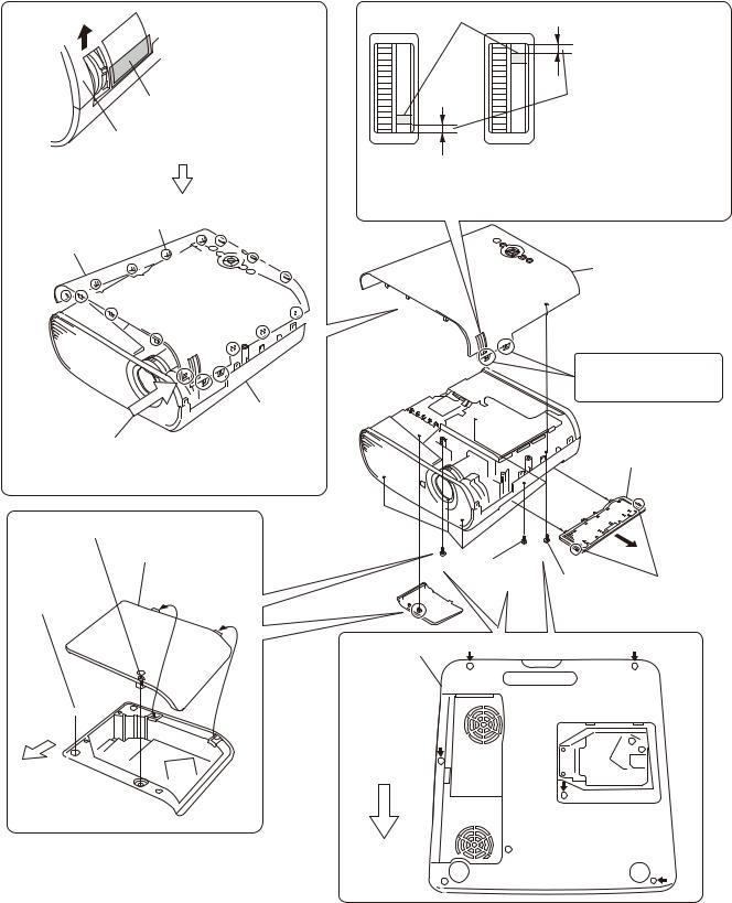
1-3-1. Upper Case Assembly
Press here strongly.
Remove the Upper case assembly in the direction of the arrow.
Disengage the claws at
the 17 locations respectively.
Upper case assembly
 Lower case pack
assembly
Caution :
Remove the upper case assembly from this corner.
When attaching the upper case assembly, attach it while aligning with the lower case pack assembly
starting from this corner.
Loosen screw.
Lamp door
Screw
(+P M3 x 6)

Front Side
of Unit
Zoom adjust gear knob
Caution :
If the spacings in the top and bottom are not equal, go to “Assembling method of optical unit assembly and Focus/Zoom adjust assembly”. (Refer to section 1-3-8. Steps 9 to 14.)
Upper case assembly
These portions are fragile. Be very careful not to damage them.
Remove the filter door in the direction of the arrow .
|
|
Screw
|
(+P M3 x 6) |
Five screws |
Two claws |
|
|
(+P M3 x 6) |
|
Lower case pack |
|
|
|
assembly |
|
|
|
Front Side of Unit


1-2 |
VPL-ES7 |

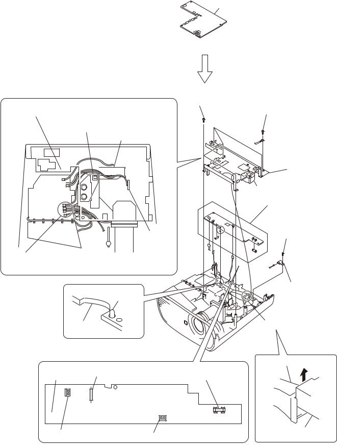
1-3-2. Rear Case Pack Assembly
|
|
Route the speaker harness |
Rear case pack assembly, etc. |
under the MB bracket. |
|
|
||
|
Rear Side |
Main board |
|
J11 |
|
Two screws |
of Unit |
|
(+K 3 x 12) |
|
|
VPL-EX7
Speaker harness
Six hexagon screws
Rear case pack assembly
Rear Side of Unit
Speaker
Two screws (+PWH 3 x 6)
Rear case pack assembly
VPL-ES7 Rear case pack assembly
 Four hexagon screws
  Two screws (+K 3 x 12)
Rear case pack assembly
VPL-EX7IN
Eight hexagon screws  Two screws (+K 3 x 12)
Rear case pack assembly
VPL-EX70
 Eight hexagon screws
Two screws (+K 3 x 12)
1-3-3. Main Board
Rear case pack assembly, etc.
Two screws (+PWH 3 x 6)
Shield
(Refer to section 1-3-2, steps 1 to 4.) |
Shield |
|
Three screws
(+PWH 3 x 6)
J11 |
|
|
|
Main board |
|
|
|
|
|
J17 |
J16 |
|
|
|
|
|
J26 |
Main board |
|
|
|
J21 |
|
|
|
|
J20 |
|
|
Remove the |
J14 |
|
J6 |
|
twelve connectors. |
J19 |
J23 |
||
|
|
J18 |
J24 |
J22 |
|
|
|
||
VPL-ES7 |
1-3 |
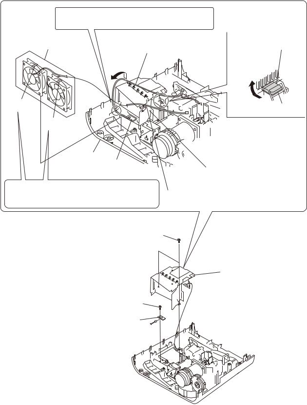
1-3-4. Power Board and Thermal Sensor Board
Main board
(Refer to section 1-3-3, steps 2 to 6.)
|
|
Five tapping screws |
|
Check to see that the seven connectors are |
(PAN M3 x 7) |
||
Screw |
|||
protruding from the MB bracket. |
|
||
Be careful that the harnesses must not override on |
(+PSW M4 x 6) |
||
|
|||
top of this port or must not be pinched by this portion. |
|
||
|
Lamp nozzle assembly |
|
|
|
|
MB bracket |
|
|
|
Fan |
|
|
|
Power board |
|
|
|
Tapping screw |
|
|
Door detection |
(PAN M3 x 7) |
|
|
switch board |
|
|
Caution : |
|
J1 |
|
When attaching the MB bracket, bind the four harnesses into the shape |
|||
|
|||
of “U” and attaching them to the MB bracket. |
|
||
|
|
Thermal sensor board |
|
|
Dowel |
|
|
Power board |
Lamp nozzle assembly |
||
|
|
Lamp nozzle assembly |
|
CN701 |
Miniature fuse-links (F602) |
Fuse (H.B.C.) |
|
(F601) |
|||
|
|||
Power board
|
|
|
|
|
|
|
|
|
|
CN605 |
|
|
|
|
CN603 Remove the three connectors. |
||||
Remove the fan in the direction of the arrow.
1-4 |
VPL-ES7 |
1-3-5. Front Case Assembly and IR Sensor Board
Tapping screw (PAN M3 x 7)
J7
Front case assembly
Logo
IR sensor board
Sheet
Lens cap |
Four claws |
1-3-6. Fan (Exhaust)-1
Lamp door |
MB bracket |
|
|
|
Power board |
(Refer to section 1-3-1, steps 2 to 4.) |
|
|
(Refer to section 1-3-4, steps 2 to 8.) |
Lamp connector assembly
Door detection switch harness
Caution :
Because the harness has the shape of flat cross-section, do not insert the harness into the harness clamp section with excessive force.
Find out the direction in which the harness can be inserted easily, and then insert the harness.
|
Harness |
No good |
Good |
Harness clamp section
Lamp assembly
Front case assembly
(Refer to section 1-3-5.)
Screw
(+PWH 3 x 6)
Lamp box assembly
Loosen two screws.
VPL-ES7 |
1-5 |
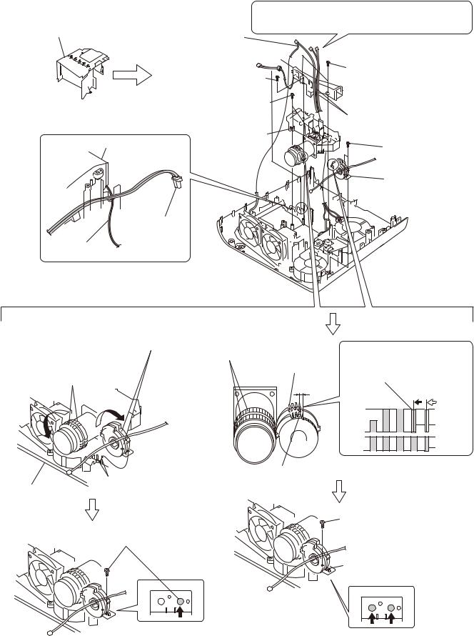
1-3-7. Fan (Exhaust)-2
Caution :
When attaching the lamp box assembly, insert the door detection switch harness into the groove of the lower case pack assembly.
Fan (Exhaust)
80*25 AD0812HB/HB
Remove the protrusion in theRemove the door detection switch direction of the arrow .
harness in the direction of the arrow .
UB mark is |
|
protrusion |
indicated. |
|
|
|
|
|
HB mark is |
|
|
|
|
|
indicated. |
|
|
Lower case pack |
|
|
assembly |
Door detection |
|
|
Lamp box assembly |
|
|
switch board |
|
Caution :
Two exhaust fans are the two different fans having the difference
characteristics. Be careful not to make mistake in choosing the Remove the fan harness in the direction of the arrow . desired fan by confirming the indication on the fans.
Two tapping screws
(PAN M3 x 7)
Lamp box assembly
Tapping screw
(PAN M3 x 7)
Door detection switch board
CN1
1-6 |
VPL-ES7 |
1-3-8. Optional Unit Assembly
|
|
Caution : |
|
|
Door detection |
When attaching the lamp nozzle assembly, route that harnesses |
|
Lamp box assembly |
in between the lamp nozzle assembly and optical unit assembly. |
||
switch harness |
|
|
|
|
Lamp nozzle assembly |
|
|
Tapping screw |
|
Two tapping screws |
|
(PH W/FLA M3 x 10L PT ZN) |
(PAN M3 x 7) |
||
(Refer to section 1-3-6, steps 5 to 9) and |
Three tapping screws |
|
|
(PAN M3 x 7) |
|
Thermal sensor harness, |
|
(refer to section 1-3-7, steps 1,2, 4 to 6.) |
|
|
|
|
Optical unit |
Fan harness |
|
|
|
||
Lamp nozzle assembly |
assembly |
Two tapping screws |
|
|
|
|
(PAN M3 x 7) |
|
|
|
Focus/Zoom adjust |
|
|
|
assembly |
Lamp connector assembly
CON thermal
145MM wire
Assembling method of optical unit assembly and
Focus/Zoom adjust gears assembly
Attach the Focus/Zoom Adjust assembly into the two dowels of the lower case pack assembly after rotating the
Focus/Zoom Adjust assembly as far as it can be rotated in the direction of clockwise direction.
Lens: Focus/Zoom gears
Lens: Rotate the Focus/Zoom gears in
the counter-clockwise direction as far Zoom adjust gear as it can be rotated.
Rotate the zoom adjust gear in the counter-clockwise direction by one tooth. Then, engage these gears with the corresponding lens gears.
Focus adjust gear
Two dowels
Lower case pack assembly
Fix the Focus/Zoom Adjust assembly tentatively with the screw.
Attach the other screw while fixing the gear position.
Tighten the screw finally that has been tightened tentatively.
VPL-ES7 |
1-7 |

1-3-9. Lamp Power Supply
Lamp box assembly |
|
Lamp nozzle assembly |
|
Fan (Exhaust) |
Optical unit assembly |
||
80*25 AD0812HB/HB |
|||
|
|
||
|
|
Focus/Zoom adjust |
|
|
|
assembly |
|
(Refer to section 1-3-6, steps 5 to 9) and |
(Refer to section 1-3-8, steps 2 to 8.) |
||
(refer to section 1-3-7, steps 1 to 6.) |
|
|
|
|
Mylar ballast |
Lamp connector |
|
Two harnesses |
|
assembly |
|
|
|
||
Two tapping screws |
|
|
|
(PAN M3 x 7) |
|
|
|
Mylar ballast
Lamp power supply
X1
CN1
Claw
 Door detection switch board
Caution :
When re-assembling the machine, route the respective harnesses and
wires at the specified locations as shown.
|
|
Route the Lamp connector |
|
assembly between them. |
|
Lamp power supply |
Route the harness |
|
through the hole of |
|
this sheet. |
|
Door detection switch board |
Door detection |
|
switch board |
Lamp power supply |
Remove the lamp power supply in the direction of the arrow .

1-8 |
VPL-ES7 |

1-3-10. Fan
Lamp box assembly
(Refer to section 1-3-6, steps 5 to 9) and
(refer to section 1-3-7, steps 1,2, 4 to 6.)
|
Tapping screw |
|
(PH W/FL M3 x 35 NI D-PT) |
|
Dowel |
Prism duct |
Two tapping screws |
(PAN M3 x 7) |
Two tapping screws  (PH W/FLA M3 x 10L PT ZN)
Fan
70*70*25 240MM AB07012UB
 Lamp nozzle assembly
Optical unit assembly
Focus/Zoom adjust assembly
(Refer to section 1-3-8, steps 2 to 8.)
Harness
Tapping screw (PAN M3 x 7)
 Washer
 Fan
Fan
75*75*30 145MM AB7512UB
 Dowel
Dowel
Prism duct
Prism duct
Thermal sensor board
VPL-ES7 |
1-9 |
1-4. 3D GAMMA Service Tool Application Software
Feature:
The Ernie Service Tool is the application software for performing the tasks such as reading out and writing of the 3D GAMMA data on the projector that is connected to a PC via a communication function. The Ernie Service Tool has the following features.
.It can read 3D GAMMA data from a set and save it in a file.
.It can write 3D GAMMA data in a PC into a set.
When the optical unit is replaced, write 3D GAMMA data recorded on the CD-ROM, which is supplied together with the optical unit, into a set using the application software.
.VPL-ES7 set has not RS-232C terminal, use the QUICK ACCESS Assy.
.Remove the rubber cap on the upper left of the rear side of the unit.
|
|
|
|
QUICK ACCESS Assy |
|
|
|
RS-232C |
|
|
|
CN 5P |
J12 |
PC |
|
QUICK ACCESS |
Set |
|||
|
Straight |
Dsub |
Assy |
|
CN J8 |
Main board CN |
|
|
|||||
|
cable |
9pin |
|
|
5pin |
|
|
|
|
|
|||
(Parts No. A-1568-125-A)
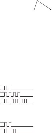
1-5. Indicator
The error status of the this units are indicated by the type of flashing of indicator. The top cover has the ON/STANDBY indicator and the LAMP/COVER indicator. Various error contents are indicated by the type of flashing of indicator. For details of the types of indicator flashing and the error statuses, refer to the list shown below.
ON/STANDBY Indicator (Red flashing)
Error Name |
Flash Frequency |
Status |
Temperature Error
Fan Error
Power Error
ON
OFF
ON
OFF
ON
OFF
2 Times |
The temperature of the equipment is high. |
4 Times |
Each fan dose not work normally. |
6 Times |
The power is not turned on correctly. |
LAMP/COVER Indicator (Orange flashing)
Error Name |
Flash Frequency |
Status |
Cover Error
Lamp Error
ON
OFF
ON
OFF
2 Times The lamp or filter cover is opened.
3 Times The UHP lamp is not lighting.
1-10 |
VPL-ES7 |
1-6. Circuit Description
Main Board:
Video input block*1
The video input has two channels: Composite video and S-Video. The 2-channel inputs are sent directly to the video processor, and converted to the digital data by the built-in AD converter of the video processor.
PC input block
There are two channels: Input A and Input B, one of which is selected with the toggle switch. The selected output is input to the video processor and the video buffer. At the video processor, the signal is converted to the digital data by the built-in AD converter. The signal input to the video buffer is output as a monitor out.
To Input A, PC signals, component signals, and video GBR signals can be input. To Input B, only PC signals can be input. (VPL-EX7IN can input only PC signals.)
Audio input block*1
Stereo mini jack input. The L/R input is synthesized internally into a monaural signal. The signal is synthesized by a resistance, so the output level varies between the case where only one channel is input and the case where both channels are input. The standard is prescribed under the condition where only one channel is input.
Monitor output block (PC)
The signals input to Input A and Input B are output. The signal of the channel that is selected with the input toggle switch is output. No output is made if Video or S-Video is selected.
Monitor output block (Audio)*1
The signal input to the audio input is output. This output is variable with the volume control. If a cable is connected to this connector, the output from the built-in speaker stops.
Video processor & System control block
PW-190 made by Pixelworks Inc. is used. This IC performs pixel number conversion, aspect conversion, and OSD addition to the input signals. This IC also controls brightness, sharpness, chroma, and hue.
In addition, the built-in CPU controls the system.
Control target: Control panel, OSD display, lamp cover switch, filter door switch, LED control, serial control
LCD timing generator (DSD) block
The IC for LCD panel made by Sony is used. This IC generates the timing for driving the LCD panel. This uses the method that inverts the driving direction for each frame. In addition to timing generation, this IC performs white balance adjustment, gamma adjustment, and color shading adjustment.
LCD driver block
The drive IC for LCD panel made by Sony is used. This drives the LCD panel in a 12-phase drive method at the timing generated by the timing generator IC. The GBR and the circuit for three channels are equipped.
*1: Not valid for VPL-EX7IN.
VPL-ES7 |
1-11 |
 Loading...