


TCM3 1L
Table of contents
 Loading...
Published by JA/JY 0966 BU TV Consumer Care, the Netherlands Subject to modification EN 3122 785 18650
2009-Jun-05
©
Copyright 2009 Koninklijke Philips Electronics N.V.
All rights reserved. No part of this publication may be reproduced, stored in a
retrieval system or transmitted, in any form or by any means, electronic, mechanical,
photocopying, or otherwise without the prior permission of Philips.
Colour Television Chassis
TCM3.1L
LA
Click
Click
18520_000_090309.eps
090316
Contents Page Contents Page
1. Revision List 2
2. Technical Specifications and Connections 2
3. Precautions, Notes, and Abbreviation List 4
4. Mechanical Instructions 8
5. Service Modes, Error Codes, and Fault Finding 12
6. Alignments 20
7. Circuit Descriptions 22
8. IC Data Sheets 25
9. Block Diagrams
Wiring Diagram 32" (Click) 37
Wiring Diagram 42" (Click) 38
Block Diagram 39
10. Circuit Diagrams and PWB Layouts Drawing PWB
PSU: Power Supply Unit (32")
(A1) 40 41-42
PSU: Power Supply Unit (42") (A1) 43 45-46
PSU: Power Supply Unit (42") (A2) 44 45-46
SSB: DC/DC (B01) 47 58-63
SSB: MT822x Processor (B02) 48 58-63
SSB: DDR SD-RAM (B03) 49 58-63
SSB: Tuner (B04) 50 58-63
SSB: HDMI (B05) 51 58-63
SSB: I/O - VGA, USB, S-Video (B06) 52 58-63
SSB: Digital Analog Converter, DAC (B07) 53 58-63
SSB: I/O - Connectivity YPbPr (B08) 54 58-63
SSB: MUX and DEMUX (B09) 55 58-63
SSB: Audio Amplifier (B10) 56 58-63
SSB: MCU Stand-by (B11) 57 58-63
Side Control Panel (E) 64 65
IR Panel (J) 66 67
Revision List
EN 2 TCM3.1L LA1.
2009-Jun-05
1. Revision List
Manual xxxx xxx xxxx.0
• First release.
2. Technical Specifications and Connections
Index of this chapter:
2.1 Technical Specifications
2.2 Directions for Use
2.3 Connection Overview
2.4 Chassis Overview
Notes:
• Figures can deviate due to the different set executions.
• Specifications are indicative (subject to change).
2.1 Technical Specifications
For on-line product support please use the links in Table 2-1.
Here is product information available, as well as getting started,
user manuals, frequently asked questions and software &
drivers.
Table 2-1 Described Model numbers
2.2 Directions for Use
Click on the hyperlinks in table above.
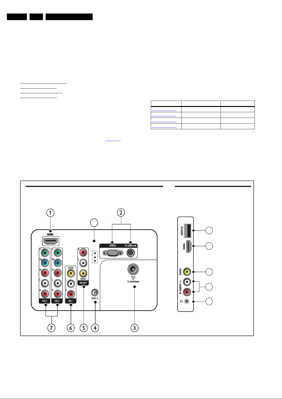
2.3 Connection Overview
Figure 2-1 Rear and side I/O connections
CTN Styling Published in SM
32PFL3404/77
Click 3122 785 18650
32PFL3404/78
Click 3122 785 18650
42PFL3604/77
Click 3122 785 18650
42PFL3604/78
Click 3122 785 18650
18650_001_090603.eps
090603
srotcennoc ediS
1
2
5
3
4
1
2
5
3
4
srotcennoc Rear
8
IR out
Technical Specifications and Connections
EN 3TCM3.1L LA 2.
2009-Jun-05
2.3.1 Side connections
Note: The following connector colour abbreviations are used
(acc. to DIN/IEC 757): Bk= Black, Bu= Blue, Gn= Green, Gy=
Grey, Rd= Red, Wh= White, and Ye= Yellow.
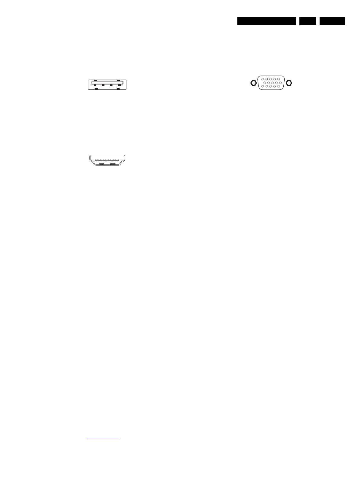
1 - USB2.0
Figure 2-2 USB (type A)
1-+5V k
2 -Data (-) jk
3 -Data (+) jk
4 -Ground Gnd H
2 - HDMI: Digital Video, Digital Audio - In
Figure 2-3 HDMI (type A) connector
1 -D2+ Data channel j
2 -Shield Gnd H
3 -D2- Data channel j
4 -D1+ Data channel j
5 -Shield Gnd H
6 -D1- Data channel j
7 -D0+ Data channel j
8 -Shield Gnd H
9 -D0- Data channel j
10 - CLK+ Data channel j
11 - Shield Gnd H
12 - CLK- Data channel j
13 - n.c.
14 - n.c.
15 - DDC_SCL DDC clock j
16 - DDC_SDA DDC data jk
17 - Ground Gnd H
18 - +5V j
19 - HPD Hot Plug Detect j
20 - Ground Gnd H
3 & 4 - Cinch: Video CVBS - In, Audio - In
Ye - Video CVBS 1 V
PP
/ 75 Ω jq
Wh - Audio L 0.5 V
RMS
/ 10 kΩ jq
Rd - Audio R 0.5 V
RMS
/ 10 kΩ jq
5 - Mini Jack: Audio Head phone - Out
Bk - Head phone 32 - 600 Ω / 10 mW ot
2.3.2 Rear Connections
1 - HDMI 1 & 2: Digital Video, Digital Audio - In
See HDMI side connector.
2 - VGA/PC: Video RGB - In
Figure 2-4 VGA Connector
1 -Video Red 0.7 V
PP
/ 75 Ω j
2 -Video Green 0.7 V
PP
/ 75 Ω j
3 -Video Blue 0.7 V
PP
/ 75 Ω j
4-n.c.
5 - Ground Gnd H
6 - Ground Red Gnd H
7 - Ground Green Gnd H
8 - Ground Blue Gnd H
9-+5V
DC
+5 V j
10 - Ground Sync Gnd H
11 - n.c.
12 - DDC_SDA DDC data j
13 - H-sync 0 - 5 V j
14 - V-sync 0 - 5 V j
15 - DDC_SCL DDC clock j
2 - PC Audio: Mini Jack: VGA Audio - In
Bk - Audio L/R 0.5 V
RMS
/ 10 kΩ jq
3 - Aerial - In
- - IEC-type (EU) Coax, 75 Ω D
4 - Mini Jack: Service Connector (UART)
1 - Ground Gnd H
2 - UART_TX Transmit k
3 - UART_RX Receive j
5 - AV-Out: Cinch: Video CVBS - Out, Audio - Out
Ye - Video CVBS 1 V
PP
/ 75 Ω kq
Wh - Audio L 0.5 V
RMS
/10 kΩ kq
Rd - Audio R 0.5 V
RMS
/ 10 kΩ kq
6 - AV-1: Cinch: Video CVBS - In, Audio - In
Ye - Video CVBS 1 V
PP
/ 75 Ω jq
Wh - Audio L 0.5 V
RMS
/ 10 kΩ jq
Rd - Audio R 0.5 V
RMS
/ 10 kΩ jq
7 - CVI-1&2: Cinch: Video YPbPr - In, Audio - In
Gn - Video Y 1 V
PP
/ 75 Ω jq
Bu - Video Pb 0.7 V
PP
/ 75 Ω jq
Rd - Video Pr 0.7 V
PP
/ 75 Ω jq
Wh - Audio L 0.5 V
RMS
/ 10 kΩ jq
Rd - Audio R 0.5 V
RMS
/ 10 kΩ jq
8 - IR Out (if present)
1 - Ground Gnd H
2-OIRI-IN k
3 - Ground Gnd H
2.4 Chassis Overview
Refer to chapter Block Diagrams for PWB/CBA locations.
1 2 3 4
E_06532_022.eps
300904
19
1
18 2
E_06532_017.eps
250505
1
6
10
11
5
15
E_06532_002.eps
171108

Precautions, Notes, and Abbreviation List
EN 4 TCM3.1L LA3.
2009-Jun-05
3. Precautions, Notes, and Abbreviation List
Index of this chapter:
3.1 Safety Instructions
3.2 Warnings
3.3 Notes
3.4 Abbreviation List
3.1 Safety Instructions
Safety regulations require the following during a repair:
• Connect the set to the Mains/AC Power via an isolation
transformer (> 800 VA).
• Replace safety components, indicated by the symbol h,
only by components identical to the original ones. Any
other component substitution (other than original type) may
increase risk of fire or electrical shock hazard. Of de set
ontploft!
Safety regulations require that after a repair, the set must be
returned in its original condition. Pay in particular attention to
the following points:
• Route the wire trees correctly and fix them with the
mounted cable clamps.
• Check the insulation of the Mains/AC Power lead for
external damage.
• Check the strain relief of the Mains/AC Power cord for
proper function.
• Check the electrical DC resistance between the Mains/AC
Power plug and the secondary side (only for sets that have
a Mains/AC Power isolated power supply):
1. Unplug the Mains/AC Power cord and connect a wire
between the two pins of the Mains/AC Power plug.
2. Set the Mains/AC Power switch to the “on” position
(keep the Mains/AC Power cord unplugged!).
3. Measure the resistance value between the pins of the
Mains/AC Power plug and the metal shielding of the
tuner or the aerial connection on the set. The reading
should be between 4.5 MΩ and 12 MΩ.
4. Switch “off” the set, and remove the wire between the
two pins of the Mains/AC Power plug.
• Check the cabinet for defects, to prevent touching of any
inner parts by the customer.
3.2 Warnings
• All ICs and many other semiconductors are susceptible to
electrostatic discharges (ESD w). Careless handling
during repair can reduce life drastically. Make sure that,
during repair, you are connected with the same potential as
the mass of the set by a wristband with resistance. Keep
components and tools also at this same potential.
• Be careful during measurements in the high voltage
section.
• Never replace modules or other components while the unit
is switched “on”.
• When you align the set, use plastic rather than metal tools.
This will prevent any short circuits and the danger of a
circuit becoming unstable.
3.3 Notes
3.3.1 General
• Measure the voltages and waveforms with regard to the
chassis (= tuner) ground (H), or hot ground (I), depending
on the tested area of circuitry. The voltages and waveforms
shown in the diagrams are indicative. Measure them in the
Service Default Mode with a colour bar signal and stereo
sound (L: 3 kHz, R: 1 kHz unless stated otherwise) and
picture carrier at 475.25 MHz for PAL, or 61.25 MHz for
NTSC (channel 3).
• Where necessary, measure the waveforms and voltages
with (D) and without (E) aerial signal. Measure the
voltages in the power supply section both in normal
operation (G) and in stand-by (F). These values are
indicated by means of the appropriate symbols.
3.3.2 Schematic Notes
• All resistor values are in ohms, and the value multiplier is
often used to indicate the decimal point location (e.g. 2K2
indicates 2.2 kΩ).
• Resistor values with no multiplier may be indicated with
either an “E” or an “R” (e.g. 220E or 220R indicates 220 Ω).
• All capacitor values are given in micro-farads (μ=× 10
-6
),
nano-farads (n =× 10
-9
), or pico-farads (p =× 10
-12
).
• Capacitor values may also use the value multiplier as the
decimal point indication (e.g. 2p2 indicates 2.2 pF).
• An “asterisk” (*) indicates component usage varies. Refer
to the diversity tables for the correct values.
• The correct component values are listed on the Philips
Spare Parts Web Portal.
3.3.3 Spare Parts
For the latest spare part overview, consult your Philips Spare
Part web portal.
3.3.4 BGA (Ball Grid Array) ICs
Introduction
For more information on how to handle BGA devices, visit this
URL: http://www.atyourservice-magazine.com
. Select
“Magazine”, then go to “Repair downloads”. Here you will find
Information on how to deal with BGA-ICs.
BGA Temperature Profiles
For BGA-ICs, you must use the correct temperature-profile.
Where applicable and available, this profile is added to the IC
Data Sheet information section in this manual.
3.3.5 Lead-free Soldering
Due to lead-free technology some rules have to be respected
by the workshop during a repair:
• Use only lead-free soldering tin. If lead-free solder paste is
required, please contact the manufacturer of your soldering
equipment. In general, use of solder paste within
workshops should be avoided because paste is not easy to
store and to handle.
• Use only adequate solder tools applicable for lead-free
soldering tin. The solder tool must be able:
– To reach a solder-tip temperature of at least 400°C.
– To stabilize the adjusted temperature at the solder-tip.
– To exchange solder-tips for different applications.
• Adjust your solder tool so that a temperature of around
360°C - 380°C is reached and stabilized at the solder joint.
Heating time of the solder-joint should not exceed ~ 4 sec.
Avoid temperatures above 400°C, otherwise wear-out of
tips will increase drastically and flux-fluid will be destroyed.
To avoid wear-out of tips, switch “off” unused equipment or
reduce heat.
• Mix of lead-free soldering tin/parts with leaded soldering
tin/parts is possible but PHILIPS recommends strongly to
avoid mixed regimes. If this cannot be avoided, carefully
clear the solder-joint from old tin and re-solder with new tin.
Precautions, Notes, and Abbreviation List
EN 5TCM3.1L LA 3.
2009-Jun-05
3.3.6 Alternative BOM identification
It should be noted that on the European Service website,
“Alternative BOM” is referred to as “Design variant”.
The third digit in the serial number (example:
AG2B0335000001) indicates the number of the alternative
B.O.M. (Bill Of Materials) that has been used for producing the
specific TV set. In general, it is possible that the same TV
model on the market is produced with e.g. two different types
of displays, coming from two different suppliers. This will then
result in sets which have the same CTN (Commercial Type
Number; e.g. 28PW9515/12) but which have a different B.O.M.
number.
By looking at the third digit of the serial number, one can
identify which B.O.M. is used for the TV set he is working with.
If the third digit of the serial number contains the number “1”
(example: AG1B033500001), then the TV set has been
manufactured according to B.O.M. number 1. If the third digit is
a “2” (example: AG2B0335000001), then the set has been
produced according to B.O.M. no. 2. This is important for
ordering the correct spare parts!
For the third digit, the numbers 1...9 and the characters A...Z
can be used, so in total: 9 plus 26= 35 different B.O.M.s can be
indicated by the third digit of the serial number.
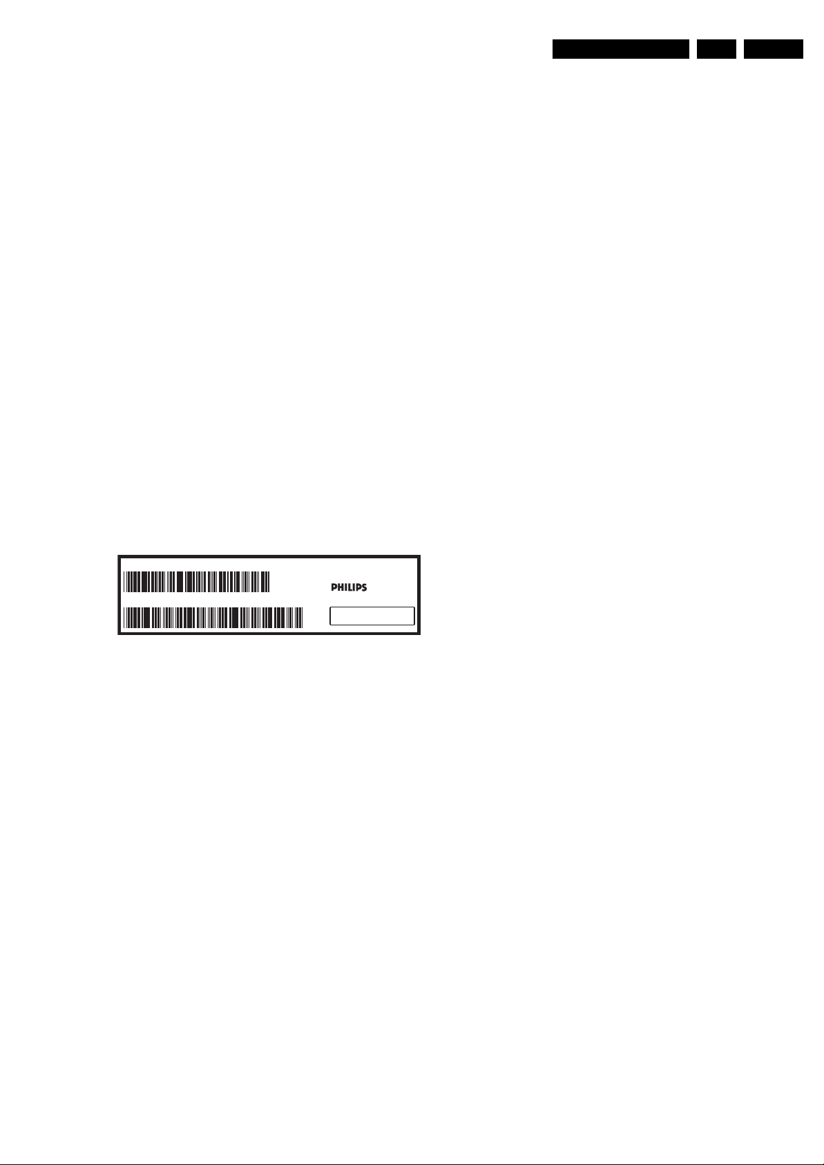
Identification: The bottom line of a type plate gives a 14-digit
serial number. Digits 1 and 2 refer to the production centre (e.g.
AG is Bruges), digit 3 refers to the B.O.M. code, digit 4 refers
to the Service version change code, digits 5 and 6 refer to the
production year, and digits 7 and 8 refer to production week (in
example below it is 2006 week 17). The 6 last digits contain the
serial number.
Figure 3-1 Serial number (example)
3.3.7 Board Level Repair (BLR) or Component Level Repair
(CLR)
If a board is defective, consult your repair procedure to decide
if the board has to be exchanged or if it should be repaired on
component level.
If your repair procedure says the board should be exchanged
completely, do not solder on the defective board. Otherwise, it
cannot be returned to the O.E.M. supplier for back charging!
3.3.8 Practical Service Precautions
• It makes sense to avoid exposure to electrical shock.
While some sources are expected to have a possible
dangerous impact, others of quite high potential are of
limited current and are sometimes held in less regard.
• Always respect voltages. While some may not be
dangerous in themselves, they can cause unexpected
reactions that are best avoided. Before reaching into a
powered TV set, it is best to test the high voltage insulation.
It is easy to do, and is a good service precaution.
3.4 Abbreviation List
0/6/12 SCART switch control signal on A/V
board. 0 = loop through (AUX to TV),
6 = play 16 : 9 format, 12 = play 4 : 3
format
AARA Automatic Aspect Ratio Adaptation:
algorithm that adapts aspect ratio to
remove horizontal black bars; keeps
the original aspect ratio
ACI Automatic Channel Installation:
algorithm that installs TV channels
directly from a cable network by
means of a predefined TXT page
ADC Analogue to Digital Converter
AFC Automatic Frequency Control: control
signal used to tune to the correct
frequency
AGC Automatic Gain Control: algorithm that
controls the video input of the feature
box
AM Amplitude Modulation
AP Asia Pacific
AR Aspect Ratio: 4 by 3 or 16 by 9
ASF Auto Screen Fit: algorithm that adapts
aspect ratio to remove horizontal black
bars without discarding video
information
ATSC Advanced Television Systems
Committee, the digital TV standard in
the USA
ATV See Auto TV
Auto TV A hardware and software control
system that measures picture content,
and adapts image parameters in a
dynamic way
AV External Audio Video
AVC Audio Video Controller
AVIP Audio Video Input Processor
B/G Monochrome TV system. Sound
carrier distance is 5.5 MHz
BLR Board-Level Repair
BTSC Broadcast Television Standard
Committee. Multiplex FM stereo sound
system, originating from the USA and
used e.g. in LATAM and AP-NTSC
countries
B-TXT Blue TeleteXT
C Centre channel (audio)
CEC Consumer Electronics Control bus:
remote control bus on HDMI
connections
CL Constant Level: audio output to
connect with an external amplifier
CLR Component Level Repair
ComPair Computer aided rePair
CP Connected Planet / Copy Protection
CSM Customer Service Mode
CTI Color Transient Improvement:
manipulates steepness of chroma
transients
CVBS Composite Video Blanking and
Synchronization
DAC Digital to Analogue Converter
DBE Dynamic Bass Enhancement: extra
low frequency amplification
DDC See “E-DDC”
D/K Monochrome TV system. Sound
carrier distance is 6.5 MHz
DFI Dynamic Frame Insertion
DFU Directions For Use: owner's manual
DMR Digital Media Reader: card reader
DMSD Digital Multi Standard Decoding
DNM Digital Natural Motion
10000_024_090121.eps
090121
MODEL :
PROD.NO:
~
S
32PF9968/10
MADE IN BELGIUM
220-240V 50/60Hz
128W
AG 1A0617 000001
VHF+S+H+UHF
BJ3.0E LA

Precautions, Notes, and Abbreviation List
EN 6 TCM3.1L LA3.
2009-Jun-05
DNR Digital Noise Reduction: noise
reduction feature of the set
DRAM Dynamic RAM
DRM Digital Rights Management
DSP Digital Signal Processing
DST Dealer Service Tool: special remote
control designed for service
technicians
DTCP Digital Transmission Content
Protection; A protocol for protecting
digital audio/video content that is
traversing a high speed serial bus,
such as IEEE-1394
DVB-C Digital Video Broadcast - Cable
DVB-T Digital Video Broadcast - Terrestrial
DVD Digital Versatile Disc
DVI(-d) Digital Visual Interface (d= digital only)
E-DDC Enhanced Display Data Channel
(VESA standard for communication
channel and display). Using E-DDC,
the video source can read the EDID
information form the display.
EDID Extended Display Identification Data
(VESA standard)
EEPROM Electrically Erasable and
Programmable Read Only Memory
EMI Electro Magnetic Interference
EPLD Erasable Programmable Logic Device
EU Europe
EXT EXTernal (source), entering the set by
SCART or by cinches (jacks)
FDS Full Dual Screen (same as FDW)
FDW Full Dual Window (same as FDS)
FLASH FLASH memory
FM Field Memory or Frequency
Modulation
FPGA Field-Programmable Gate Array
FTV Flat TeleVision
Gb/s Giga bits per second
G-TXT Green TeleteXT
H H_sync to the module
HD High Definition
HDD Hard Disk Drive
HDCP High-bandwidth Digital Content
Protection: A “key” encoded into the
HDMI/DVI signal that prevents video
data piracy. If a source is HDCP coded
and connected via HDMI/DVI without
the proper HDCP decoding, the
picture is put into a “snow vision” mode
or changed to a low resolution. For
normal content distribution the source
and the display device must be
enabled for HDCP “software key”
decoding.
HDMI High Definition Multimedia Interface
HP HeadPhone
I Monochrome TV system. Sound
carrier distance is 6.0 MHz
I
2
C Inter IC bus
I
2
D Inter IC Data bus
I
2
S Inter IC Sound bus
IF Intermediate Frequency
IR Infra Red
IRQ Interrupt Request
ITU-656 The ITU Radio communication Sector
(ITU-R) is a standards body
subcommittee of the International
Telecommunication Union relating to
radio communication. ITU-656 (a.k.a.
SDI), is a digitized video format used
for broadcast grade video.
Uncompressed digital component or
digital composite signals can be used.
The SDI signal is self-synchronizing,
uses 8 bit or 10 bit data words, and has
a maximum data rate of 270 Mbit/s,
with a minimum bandwidth of 135
MHz.
ITV Institutional TeleVision; TV sets for
hotels, hospitals etc.
LS Last Status; The settings last chosen
by the customer and read and stored
in RAM or in the NVM. They are called
at start-up of the set to configure it
according to the customer's
preferences
LATAM Latin America
LCD Liquid Crystal Display
LED Light Emitting Diode
L/L' Monochrome TV system. Sound
carrier distance is 6.5 MHz. L' is Band
I, L is all bands except for Band I
LPL LG.Philips LCD (supplier)
LS Loudspeaker
LVDS Low Voltage Differential Signalling
Mbps Mega bits per second
M/N Monochrome TV system. Sound
carrier distance is 4.5 MHz
MIPS Microprocessor without Interlocked
Pipeline-Stages; A RISC-based
microprocessor
MOP Matrix Output Processor
MOSFET Metal Oxide Silicon Field Effect
Transistor, switching device
MPEG Motion Pictures Experts Group
MPIF Multi Platform InterFace
MUTE MUTE Line
NC Not Connected
NICAM Near Instantaneous Compounded
Audio Multiplexing. This is a digital
sound system, mainly used in Europe.
NTC Negative Temperature Coefficient,
non-linear resistor
NTSC National Television Standard
Committee. Color system mainly used
in North America and Japan. Color
carrier NTSC M/N= 3.579545 MHz,
NTSC 4.43= 4.433619 MHz (this is a
VCR norm, it is not transmitted off-air)
NVM Non-Volatile Memory: IC containing
TV related data such as alignments
O/C Open Circuit
OSD On Screen Display
OTC On screen display Teletext and
Control; also called Artistic (SAA5800)
P50 Project 50: communication protocol
between TV and peripherals
PAL Phase Alternating Line. Color system
mainly used in West Europe (color
carrier= 4.433619 MHz) and South
America (color carrier PAL M=
3.575612 MHz and PAL N= 3.582056
MHz)
PCB Printed Circuit Board (same as “PWB”)
PCM Pulse Code Modulation
PDP Plasma Display Panel
PFC Power Factor Corrector (or Pre-
conditioner)
PIP Picture In Picture
PLL Phase Locked Loop. Used for e.g.
FST tuning systems. The customer
can give directly the desired frequency
POD Point Of Deployment: a removable
CAM module, implementing the CA
system for a host (e.g. a TV-set)
POR Power On Reset, signal to reset the uP
PTC Positive Temperature Coefficient,
non-linear resistor
PWB Printed Wiring Board (same as “PCB”)

Precautions, Notes, and Abbreviation List
EN 7TCM3.1L LA 3.
2009-Jun-05
PWM Pulse Width Modulation
QRC Quasi Resonant Converter
QTNR Quality Temporal Noise Reduction
QVCP Quality Video Composition Processor
RAM Random Access Memory
RGB Red, Green, and Blue. The primary
color signals for TV. By mixing levels
of R, G, and B, all colors (Y/C) are
reproduced.
RC Remote Control
RC5 / RC6 Signal protocol from the remote
control receiver
RESET RESET signal
ROM Read Only Memory
RSDS Reduced Swing Differential Signalling
data interface
R-TXT Red TeleteXT
SAM Service Alignment Mode
S/C Short Circuit
SCART Syndicat des Constructeurs
d'Appareils Radiorécepteurs et
Téléviseurs
SCL Serial Clock I
2
C
SCL-F CLock Signal on Fast I
2
C bus
SD Standard Definition
SDA Serial Data I
2
C
SDA-F DAta Signal on Fast I
2
C bus
SDI Serial Digital Interface, see “ITU-656”
SDRAM Synchronous DRAM
SECAM SEequence Couleur Avec Mémoire.
Color system mainly used in France
and East Europe. Color carriers=
4.406250 MHz and 4.250000 MHz
SIF Sound Intermediate Frequency
SMPS Switched Mode Power Supply
SoC System on Chip
SOG Sync On Green
SOPS Self Oscillating Power Supply
SPI Serial Peripheral Interface bus; a 4-
wire synchronous serial data link
standard
S/PDIF Sony Philips Digital InterFace
SRAM Static RAM
SRP Service Reference Protocol
SSB Small Signal Board
STBY STand-BY
SVGA 800 × 600 (4:3)
SVHS Super Video Home System
SW Software
SWAN Spatial temporal Weighted Averaging
Noise reduction
SXGA 1280 × 1024
TFT Thin Film Transistor
THD Total Harmonic Distortion
TMDS Transmission Minimized Differential
Signalling
TXT TeleteXT
TXT-DW Dual Window with TeleteXT
UI User Interface
uP Microprocessor
UXGA 1 600 × 1200 (4:3)
V V-sync to the module
VESA Video Electronics Standards
Association
VGA 640 × 480 (4:3)
VL Variable Level out: processed audio
output toward external amplifier
VSB Vestigial Side Band; modulation
method
WYSIWYR What You See Is What You Record:
record selection that follows main
picture and sound
WXGA 1280 × 768 (15:9)
XTAL Quartz crystal
XGA 1024 × 768 (4:3)
Y Luminance signal
Y/C Luminance (Y) and Chrominance (C)
signal
YPbPr Component video. Luminance and
scaled color difference signals (B-Y
and R-Y)
YUV Component video
Mechanical Instructions
EN 8 TCM3.1L LA4.
2009-Jun-05
4. Mechanical Instructions
Index of this chapter:
4.1 Service Positions
4.2 Cable Dressing and Taping
4.3 Assy/Panel Removal
4.4 Set Re-assembly
Notes:
• Figures below can deviate slightly from the actual situation,
due to the different set executions.
4.1 Service Positions
For easy servicing of this set, there are a few possibilities
created:
• The buffers from the packaging.
• Foam bars (created for Service).
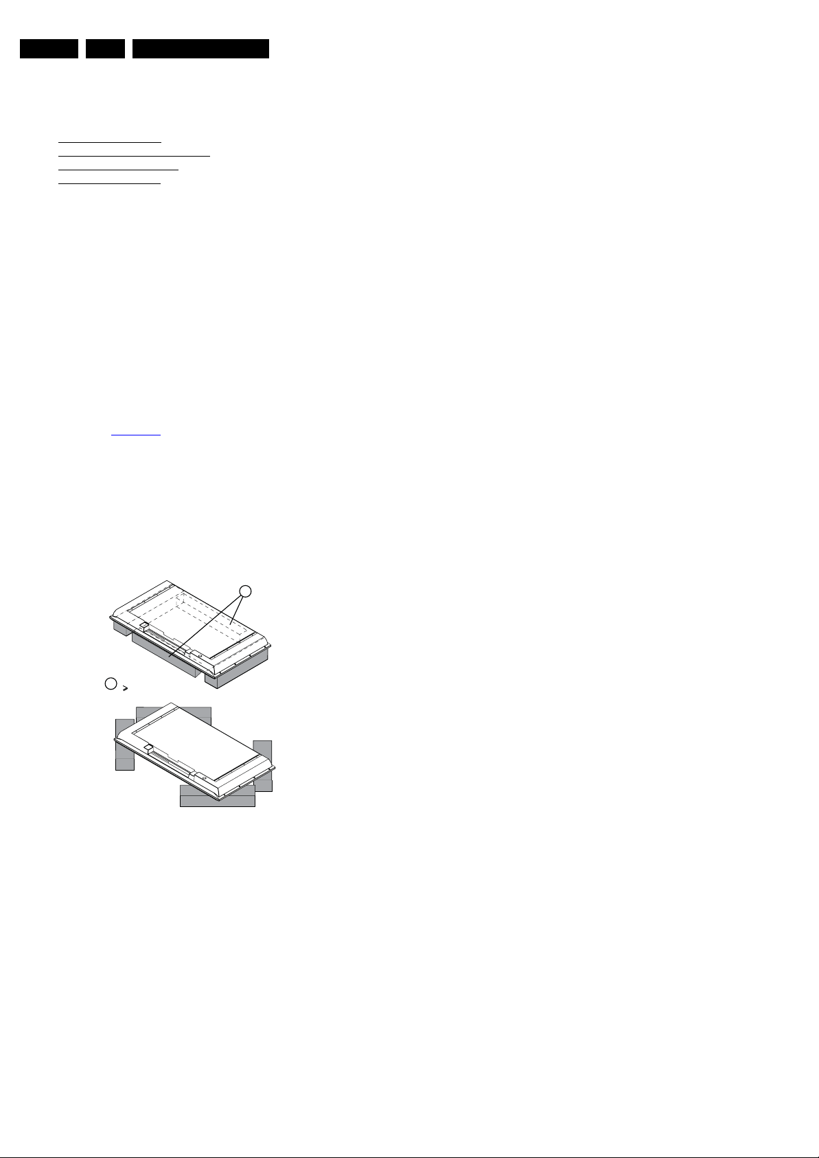
4.1.1 Foam Bars
The foam bars (order code 3122 785 90580 for two pieces) can
be used for all types and sizes of Flat TVs.
See figure Figure 4-1
for details. Sets with a display of 42" and
larger, require four foam bars [1]. Ensure that the foam bars
are always supporting the cabinet and never only the display.
Caution: Failure to follow these guidelines can seriously
damage the display!
By positioning the TV face down on the (ESD protective) foam
bars, a stable situation is created to perform measurements
and alignments. By placing a mirror under the TV, the screen
can be monitored.
Figure 4-1 Foam bars
E_06532_018.eps
171106
1
Required for sets
42"
1
Mechanical Instructions
EN 9TCM3.1L LA 4.
2009-Jun-05
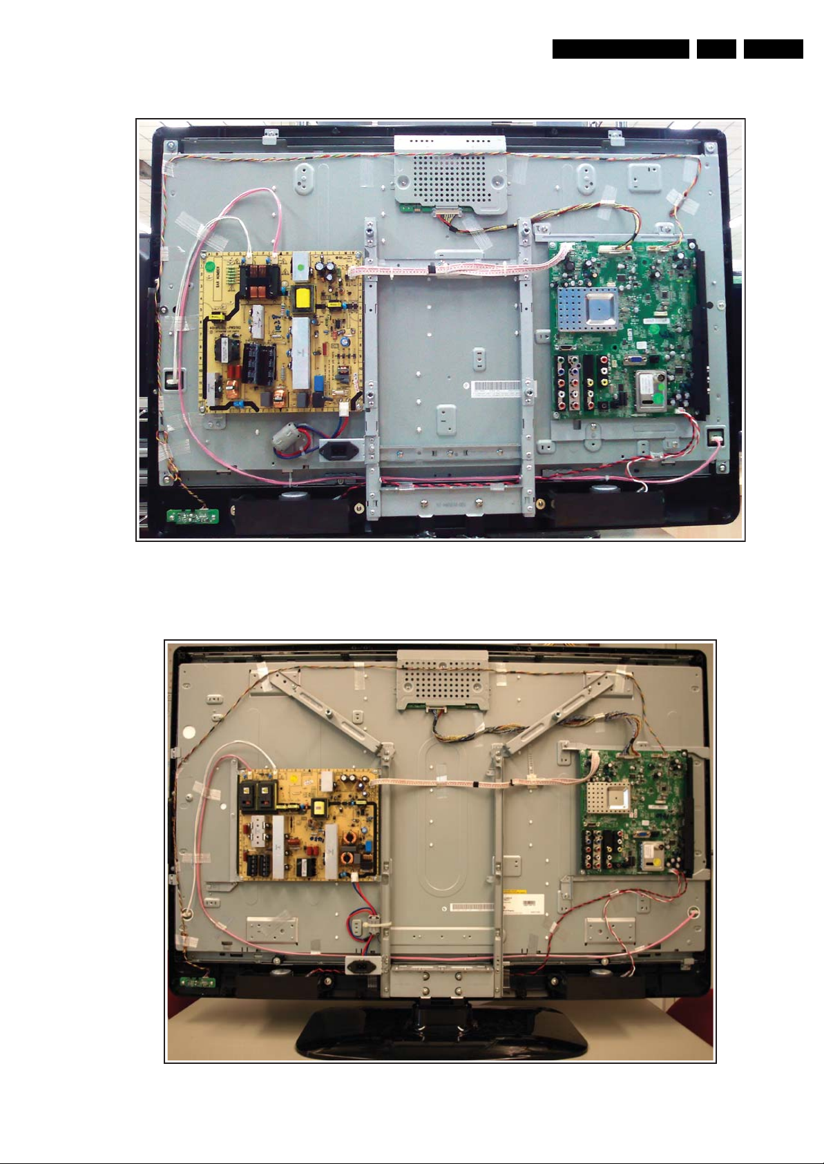
4.2 Cable Dressing and Taping
Figure 4-2 Cable dressing and taping 32" model
Figure 4-3 Cable dressing and taping 42" model
18520_105_090318.eps
090603
18520_100_090309.eps
090309
Mechanical Instructions
EN 10 TCM3.1L LA4.
2009-Jun-05
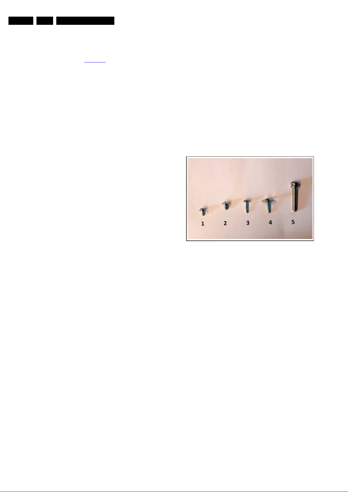
4.3 Assy/Panel Removal
Caution: It is mandatory to remount screws at their original
position during re-assembly. Failure to do so may result in
damaging the SSB. Refer to Figure 4-4
for details.
4.3.1 Rear Cover
Warning/Notes:
• Disconnect the mains power cord before rear cover
removal.
• It is not necessary to remove the stand while removing the
rear cover.
• Re-use the original screws when re-assembling the TV.
1. Remove all screws of the rear cover.
Important: Be sure to re-use the same screws when
remounting the rear cover, as these screws have a 30
degrees thread instead of the common used 45 degrees
thread.
2. Lift the rear cover from the TV. Make sure that wires and
flat coils are not damaged while lifting the rear cover from
the set.
4.3.2 Speakers
Each speaker unit is mounted (in rubber) with two screws.
When defective, replace the whole unit.
4.3.3 IR & LED Board
1. Remove the two screws that hold the assy.
2. Unplug the connector on the board (be aware of the
connector lock).
When defective, replace the whole unit.
4.3.4 Key Board Control Panel
1. Remove the two screws that hold the assy.
2. Unplug the connectors on the board.
When defective, replace the whole unit.
4.3.5 Main Supply Panel
1. Unplug all connectors (be aware of the connector locks).
2. Remove the fixation screws (screw #1).
3. Take the board out.
When defective, replace the whole unit.
4.3.6 Small Signal Board (SSB)
1. Unplug all connectors on the SSB.
2. Remove all screws (screw #1) that hold the board.
3. The SSB can now be taken out of the set, together with the
side connector cover.
4.3.7 LCD Panel
Description below is based upon the 42" model with LG display.
Disassembly method of other LCD panels is comparable to the
one described below. See also “Mechanical layout” drawings.
4. Unplug and remove all cables.
5. Remove the Main Supply Panel and Small SIgnal Board as
described earlier.
6. Remove all metal brackets that are mounted on the panel
(be aware of the different screws used, see figure “Used
screws”):
– Two VESA holder brackets at the top (screw #2).
– Two SSB holder brackets (screws #2 and #3).
– Two central holder brackets (screw #2).
– One PSU holder bracket (screw#1).
7. Remove the stand [1] (screw #5).
8. Remove the subframe of the stand [2] (screw #2).
9. Remove the brackets [3] (screw #3) that secure the LCD
panel, and remove screws #4 at the bottom of the LCD.
10. The LCD panel can now be lifted from the front cabinet.
Figure 4-4 Used screws
18520_101_090311.eps
090311
Mechanical Instructions
EN 11TCM3.1L LA 4.
2009-Jun-05
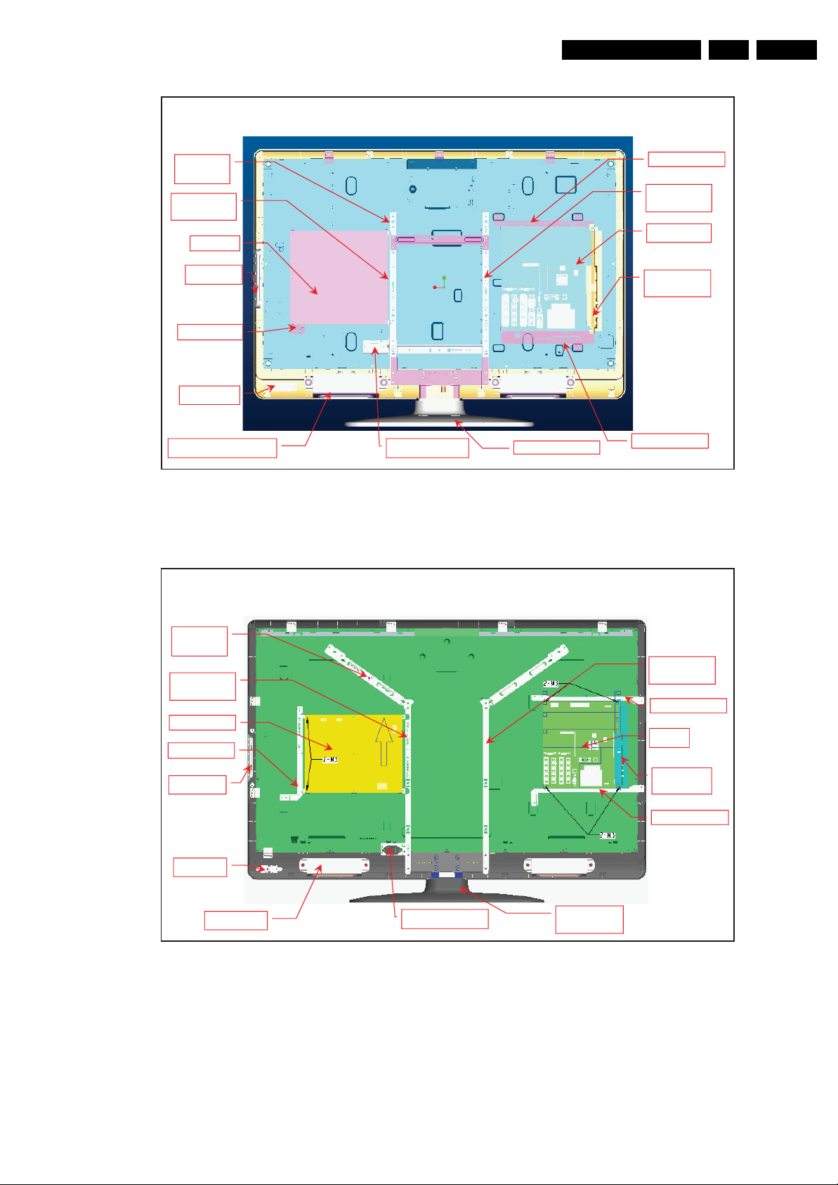
Figure 4-5 Mechanical layout 32" model
Figure 4-6 Mechanical layout 42" model
4.4 Set Re-assembly
To re-assemble the whole set, execute all processes in reverse
order.
Notes:
• While re-assembling, make sure that all cables are placed
and connected in their original position.
• Pay special attention not to damage the EMC foams in the
set. Ensure that EMC foams are mounted correctly.
32 Mechanical layout definition
Button
SIDE AV
bracket
SSB
IR - L en s
Stand
2 * Speaker
AC-In Bracket
IPB
VESA
200*200
IP B b rac ke t
Panel
bracket L
Panel
bracket R
SSB bracket B
SSB bracket U
18520_104_090318.eps
090318
42 Mechanical layout definition
SIDE AV
bracket
SSB
Button
IR - L ED
Stand
bracket
2 * Speaker
AC-In Bracket
IPB
VESA
400*400
IPB bracket
Panel
bracket L
Panel
bracket R
SSB bracket B
SSB bracket U
18520_102_090318.eps
090318

Service Modes, Error Codes, and Fault Finding
EN 12 TCM3.1L LA5.
2009-Jun-05
5. Service Modes, Error Codes, and Fault Finding
Index of this chapter:
5.1 Measurement Conditions
5.2 Service Modes
5.3 Service Tools
5.4 Error Codes
5.5 The Blinking LED Procedure (LAYER-2 codes)
5.6 Fault Finding and Repair Tips
5.7 Software Upgrading
5.1 Measurement Conditions
Perform measurements under the following conditions:
• Service Default Mode.
• Video: Colour bar signal.
• Audio: 3 kHz left, 1 kHz right.
5.2 Service Modes
Note: For the new model range, a new remote control (RC) is
used with some renamed buttons. This has an impact on the
activation of the Service modes. For instance the old “MENU”
button is now called “HOME” (or is indicated by a “house” icon).
Service Default mode (SDM) and Service Alignment Mode
(SAM) offer several features for the service technician, while
the Customer Service Mode (CSM) is used for communication
between the call centre and the customer.
This chassis also offers the option of using ComPair, a
hardware interface between a computer and the TV chassis. It
offers the abilities of structured troubleshooting, error code
reading, and software version read-out for all chassis.
(see also section 5.3.1 ComPair
).
5.2.1 Service Default Mode (SDM)
Purpose
To start the blinking LED procedure where only layer 2 errors
are displayed (see also section 5.4 Error Codes
).
How to Activate SDM
Use the standard RC-transmitter and key in the code “062596”,
directly followed by the “MENU” (or HOME) button.
After activating this mode, “SDM” will appear in the upper right
corner of the screen (when a picture is available).
How to Navigate
When the “MENU” (or HOME) button is pressed on the RC
transmitter, the set will toggle between the SDM and the normal
user menu (with the SDM mode still active in the background).
How to Exit SDM
Switch the set to STAND-BY via the RC-transmitter.
5.2.2 Service Alignment Mode (SAM)
Purpose
• To perform (software) alignments.
• To change option settings.
• To easily identify the used software version.
• To view operation hours.
• To display (or clear) the error code buffer.
How to Activate SAM
Via a standard RC transmitter: key in the code “062596”
directly followed by the “i+/INFO” button.
Contents of SAM (see also 6.4 Option Settings
):
• Syst. Info. Giving overview of:
– Op. Hours. During the life time cycle of the TV, a life
timer is kept. It counts the normal operation hours, not
the Stand-by hours. The actual value of the life timer is
displayed in SAM in decimal value. For every two start-
ups the counter increases by one. Min. 5 digits are
displayed in decimal digits. In detail:
• Every 2x cold start-ups, to display a picture,
increases the counter by 1 (i.e. interrupt the mains
supply 2x while the set is ON).
• Every 2x warm start-ups (from Stand-by), to
display a picture, increases the counter by 1.
• Every hour of normal operating increases the
counter by 1 (i.e. if a set is continue ON for 2 hours,
then increase the counter by 2).
• Stand-by hours are NOT counted.
– Main SW ID. Displays the loaded main SW version.
– Error Code x (where “x” is 1 to 5). The most recent
error is displayed at the upper position (for an error
explanation see section 5.4 Error Codes
).
• Clear Codes. When “arrow right” is pressed and then the
“OK” button is pressed, the error buffer is reset.
• Options. Choosing the CTN will set the options, see also
chapter 6.4 Option Settings
.
• RGB Align. This will activate the alignments sub-menu.
See chapter 6.3.2 White Point
for more details.
• NVM Editor. This will give the opportunity to directly
change values in the NVM by selecting the address and
value. Use decimal values! See chapter 6.4 Option
Settings.
• NVM Copy. For easy transfer of NVM settings:
– Copy to USB. To upload several settings from the TV
to an USB stick. See 5-1 USB Copy content
. To upload
the settings, press “arrow right” (or the “OK button),
confirm with “OK” and wait until “OK” appears. Now the
settings are stored onto the USB stick can be used to
download to another TV or other SSB. Uploading is of
course only possible if the software is running and if a
picture is available. This method is created to be able
to save the customer’s TV settings and to store them
into another SSB.
– Copy from USB. To download several settings from
the USB stick to the TV. Same way of working as with
uploading. To make sure that the download of the
channel list from USB to the TV is executed properly, it
is necessary to restart the TV and tune to a valid preset
if necessary.
Table 5-1 USB Copy content
S/N NVM USB Copy content To be copied /Remarks
1 Display settings White Point alignment,
RGB
Yes
2 Personal settings eg. Brightness, colour,
hue, equalizer, band,
head phone volume, child
lock, time, picture for-
mat...
Yes
3 Channel List Channel preset Yes
4 Options list Option code Yes
5 AGC and AFC
alignment
SSB specific No.
6 HDCP key No.
7 Model 22PFL1234D/10 Yes
8 Production serial nbr. BA1A0837123456 Yes
9 Software Version TXM21E 1.00 No. Read and display.
10 Option Code
(used display)
009 yes
11 Codes 011 000 000 000 000 No. Error detection
12 SSB 996512312345 No
13 Display 996512345678 Yes
14 PSU 996512311111 Yes
15 NVM version Supplier to advise
NVM version
No. Read and display.

Service Modes, Error Codes, and Fault Finding
EN 13TCM3.1L LA 5.
2009-Jun-05
• Tuner. This will activate the alignments sub-menu. See
chapter 6.3.1 Tuner AGC (RF AGC Take Over Point
Adjustment) for more details.
• Auto ADC. This will activate the alignments sub-menu.
See chapter 6.3.3 Auto ADC for more details.
How to Navigate
• In SAM, the menu items can be selected with the “Arrow
up/down” key on the RC-transmitter. The selected item will
be highlighted. When not all menu items fit on the screen,
move the “Arrow up/down” key to display the next/previous
menu items.
• With the “Arrow Left/Right” keys, it is possible to:
– (De) activate the selected menu item.
– (De) activate the selected sub menu.
• With the “OK” key, it is possible to activate the selected
action.
• With the “Menu/Home” key, it is possible to go back to the
previous selection.
How to Exit SAM
Switch the set to STAND-BY via the RC-transmitter.
5.2.3 Customer Service Mode (CSM)
Purpose
When a customer is having problems with his TV-set, he can
call his dealer or the Customer Helpdesk. The service
technician can then ask the customer to activate the CSM, in
order to identify the status of the set. Now, the service
technician can judge the severity of the complaint. In many
cases, he can advise the customer how to solve the problem,
or he can decide if it is necessary to visit the customer
The CSM is a read only mode; therefore, modifications in this
mode are not possible
When CSM is activated:
• A test pattern will be displayed during 3 s. This test pattern
is generated by the MT822x video processor. So if this test
pattern is shown, it could be determined that the back end
video chain (MT822x, LVDS, and display) of the SSB is
working.
• The LAYER 1 error is displayed via the blinking front LED.
Only the latest error is displayed. See also section 5.4 Error
Codes.
How to Activate CSM
Key in the code “123654” via the standard RC transmitter.
Note: Activation of the CSM is only possible if there is no (user)
menu on the screen!
How to Navigate
By means of the “Arrow up/down” button on the RC-transmitter,
one can navigate through the menus.
Contents of CSM
The contents are displayed on two pages:
• Model Number. This information is very helpful for a
helpdesk/workshop as reference for further diagnosis. In
this way, it is not necessary for the customer to look at the
rear of the TV-set. Note that if an NVM is replaced or is
initialised after corruption, this model type has to be re-
written to NVM. ComPair will foresee in a possibility to do
this.
• Production Serial Number. Displays the production code
(the serial number) of the TV. Note that if an NVM is
replaced or is initialized after corruption, this production
code has to be re-written to NVM. ComPair will foresee a in
possibility to do this.
• Software Version. Displays the current main software
version. In case of field problems that are related to
software, this software can be upgraded. As it is consumer
upgradeable, it will also be published on the Internet.
• Option Code. Gives the display codes as set in SAM. See
also section 6.4 Option Settings
.
• Codes. Gives the error code overview. See also table 5-3
Layer-2 code overview.
• SSB. Gives an identification of the SSB order code as
stored in NVM. Note that if an NVM is replaced or is
initialized after corruption, this identification number has to
be re-written to NVM. ComPair will foresee in a possibility
to do this.
• Display. Shows the 12NC of the display.
• PSU. Shows the 12NC of the Power Supply Unit.
• NVM version. Displays the SW-version that is used in the
NVM.
• HDCP key. Indicates of the HDMI keys (or HDCP keys) are
valid or not. In case these keys are not valid and the
consumer wants to make use of the HDMI functionality, the
SSB has to be replaced.
• Signal Quality/Present. Displays the received signal
quality or its presence.
• Audio System. Displays the received audio system.
• Video Format. Displays the received video format.
• Stand-by uP SW ID. Displays the current Stand-by
Processor software version.
How to Exit CSM
By pressing the “MENU/HOME” key, the OSD (i+) key, the
Stand-by key or the power down button.
16 PQ version Supplier to advise
PQ version
No. Read and display.
17 HDCP key Valid No. Are measure results
18 Signal Quality/Present Digital percentage and
analog Yes/No.
No. Are measure results
19 Audio System Detect and display No. Are measure results
20 Video Format Detect and display No. Are measure results
21 Stand-by uP SW ID Detect and display No. Read and display
S/N NVM USB Copy content To be copied /Remarks
S/N Description Explanation
1 Model Number NVM read/write (max. 16 characters)
2 Production Serial Nbr. NVM read/write (max. 16 characters)
3 Software Version Detect and Display SW version
4 Option Code Store in NVM (panel code)
5 Codes Layer-2 error code.
6 SSB 12NC NVM read/write (12 characters)
7 Display 12NC NVM read/write (12 characters)
8 PSU 12NC NVM read/write (12 characters)
9 NVM version Detect and Display NVM version
10 HDCP key Detect and display (valid/invalid)
11 Signal Quality/Present Present / No signal
12 Audio System Detect and display:
Mono, Stereo, Nicam (signal dependent)
13 Video Format Detect and display: signal dependent
14 Stand-by uP SW ID Detect and display.
Service Modes, Error Codes, and Fault Finding
EN 14 TCM3.1L LA5.
2009-Jun-05
5.3 Service Tools
5.3.1 ComPair
Introduction
ComPair (Computer Aided Repair) is a Service tool for Philips
Consumer Electronics products. and offers the following:
1. ComPair helps to quickly get an understanding on how to
repair the chassis in a short and effective way.
2. ComPair allows very detailed diagnostics and is therefore
capable of accurately indicating problem areas. No
knowledge on I
2
C or UART commands is necessary,
because ComPair takes care of this.
3. ComPair speeds up the repair time since it can
automatically communicate with the chassis (when the uP
is working) and all repair information is directly available.
4. ComPair features TV software up possibilities.
Specifications
ComPair consists of a Windows based fault finding program
and an interface box between PC and the (defective) product.
The ComPair II interface box is connected to the PC via an
USB cable. For the TV chassis, the ComPair interface box and
the TV communicate via a bi-directional cable via the service
connector(s).
The ComPair fault finding program is able to determine the
problem of the defective television, by a combination of
automatic diagnostics and an interactive question/answer
procedure.
How to Connect
This is described in the chassis fault finding database in
ComPair.
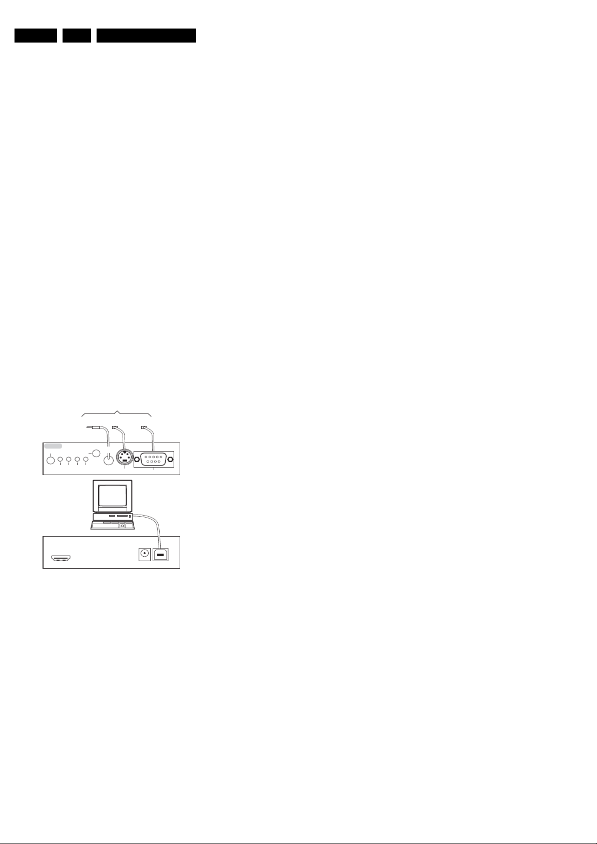
Figure 5-1 ComPair II interface connection
Caution: It is compulsory to connect the TV to the PC as
shown in the picture above (with the ComPair interface in
between), as the ComPair interface acts as a level shifter. If
one connects the TV directly to the PC (via UART), ICs will be
blown!
How to Order
ComPair II order codes:
• ComPair II interface: 3122 785 91020.
• Software is available via the Philips Service web portal.
• ComPair serial interface cable (using 3.5 mm Mini Jack
connectors): 3138 188 75051.
Note: When having problems, please contact the local support
desk.
5.4 Error Codes
5.4.1 Introduction
The error code buffer contains all detected errors since the last
time the buffer was erased. The buffer is written from top to
bottom (or left to right), new errors are logged at the top/left
side, and all other errors shift one position to the bottom/right.
When an error occurs, it is added to the list of errors, provided
the list is not full. When the error buffer is full, then the new error
is not added, and the error buffer stays intact (history is
maintained).
To prevent that an occasional error stays in the list forever, the
error is removed from the list after more than 50 hrs. of
operation/
There is a simple blinking LED procedure for board level repair
(home repair) the so called LAYER 1 errors, next to the existing
errors which are LAYER 2 errors:
• LAYER 1 errors are one digit errors
• LAYER 2 errors are two digit errors.
When is LAYER 1 or 2 available:
• In CSM mode: When entering CSM: error LAYER 1 will be
displayed by blinking LED. Only the latest error is shown.
• In SDM mode: When SDM is entered via Remote Control
code, LAYER 2 is displayed via blinking LED.
Error display on screen:
• In CSM, no error codes are displayed on screen.
• In SAM, the complete error list is shown.
If possible, check the entire contents of the error buffer. In
some situations, an error code is only the result of another error
code and not the actual cause (e.g. a fault in the protection
detection circuitry can also lead to a protection).
In case of non-intermittent faults, clear the error buffer before
starting to repair (before clearing the buffer, write down the
content, as this history can give significant information). This to
ensure that old error codes are no longer present.
5.4.2 How to Read the Error Buffer
Use one of the following methods:
• On screen via SAM (only when a picture is visible). E.g.:
– 000 000 000 000 000: No errors detected
– 017 000 000 000 000: Error code 17 is the last and only
detected error.
– 015 017 000 000 000: Error code 17 was first detected
and error code 15 is the last detected error.
• Via the Blinking LED procedure.
•Via ComPair.
5.4.3 How to Clear the Error Buffer
Use one of the following methods:
• By activation of the “Clear Codes” command in the SAM
menu.
• With a normal RC, key in sequence “062599” followed by
“OK”.
E_06532_036.eps
150208
TO
UART SERVICE
CONNECTOR
TO
UART SERVICE
CONNECTOR
TO
I
2
C SERVICE
CONNECTOR
TO TV
PC
HDMI
I
2
C only
Optional power
5V DC
ComPair II Developed by Philips Brugge
RC out
RC in
Optional
Switch
Power ModeLink/
Activity
I
2
C
ComPair II
Multi
function
RS232 /UART
Service Modes, Error Codes, and Fault Finding
EN 15TCM3.1L LA 5.
2009-Jun-05
5.4.4 Error Codes
Take notice that some errors need several minutes before they
start blinking or before they will be logged. So in case of
problems wait 2 minutes from start-up onwards, and then
check if the front LED is blinking or if an error is logged.
Table 5-2 Layer 1 code overview
Table 5-3 Layer-2 code overview
5.5 The Blinking LED Procedure (LAYER-2 codes)
5.5.1 Introduction
The software is capable of identifying different kinds of errors.
Because it is possible that more than one error can occur over
time, an error buffer is available that is capable of storing the
last five errors that occurred. This is useful if the OSD is not
working properly.
Errors can also be displayed by the blinking LED procedure.
The method is to repeatedly let the LED pulse with as many
pulses as the error code number, followed by a time period of
1.5 seconds in which the LED is “off”. Then this sequence is
repeated.
E.g. error code 4 will result in four times the sequence LED “on”
for 0.25 seconds / LED “off” for 0.25 seconds. After this
sequence the LED will be “off” for 1.5 seconds. Any RC
command terminates this sequence.
Displaying the entire error buffer
The entire error buffer can be displayed when service mode
“SDM” is entered (by remote control command
062596<MENU>). When in protection, this sequence will not
work, but than LAYER-1 error code should suffice.
In order to avoid confusion with RC signal reception blinking,
this blinking procedure is terminated when a RC command is
received.
5.5.2 How to Activate
Use one of the following methods:
• Activate the CSM. The blinking front LED will show only
the latest LAYER-1 error.
• Activate the SDM. The blinking front LED will show the
entire contents of the LAYER-2 error buffer.
Code Board
2SSB
3 Platform supply (12V detection)
Layer 2
error code
Error
Description
Detection
Method
Type Remarks
0 No Error N/A N/A N/A
14 General I
2
CI
2
C Bus Spontaneous
blinking
Communication Error
on I
2
C bus
15 Tuner I
2
C Bus Error Log
+ blinking in SDM
Communication Error
with Tuner
16 Demodulator I
2
C Bus Error Log
+ blinking in SDM
Communication Error
with TDA9886T
17 Audio amplifier I
2
C Bus Error Log
+ blinking in SDM
Communication Error
with Audio amplifier
18 NVM EEPROM I
2
C Bus Spontaneous
blinking
Communication Error
with EEPROM
Service Modes, Error Codes, and Fault Finding
EN 16 TCM3.1L LA5.
2009-Jun-05
5.6 Fault Finding and Repair Tips
5.6.1 Fault Finding Flow Charts
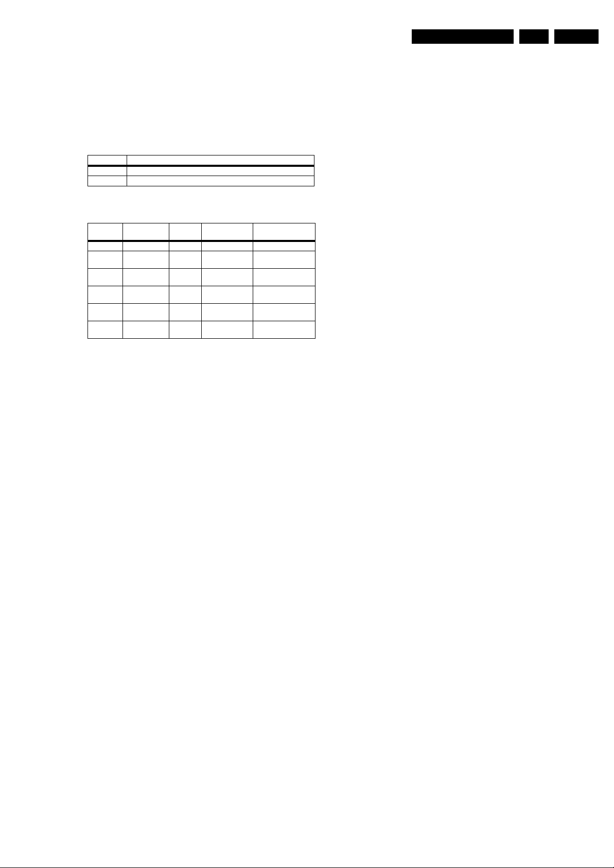
Figure 5-2 No picture, no sound, no backlight. Fuse broken.
Figure 5-3 No picture. Backlight and sound okay.
18520_204_090313.eps
090313
No Picture, no sound, no Back light, Fuse Broken
For P22,pin10 is
3.3V , OK?
For P22,pin1 is
24V , OK?
Check IPB
For P22 ,Pin 7~8
is 3.3V, OK?
Check Q10,
X5,IR_MCU,KEY,
MCU_RESET,U8.
Check main
board DV10
&+3.3V OK?
NO
NO NO
YES YES YES
Check main board
DDRV & AV12, OK?
YES
Check main board
short_protect ,
oreset#,pwr_detect
YES
Check IPB
18520_205_090313.eps
090313
No Picture, Back light & Sound OK
Check the 5V-IF
voltage of . is it
OK?
Check 33V is
OK?
Check the
voltage
of R48,U6
Yes
No
Yes
Is
Q14,C184,C197
,L54 shorted to
earth?
Replace R48 &
U6
Yes
No
check the
U2,Q13
check
D2,R184,R178
No
Service Modes, Error Codes, and Fault Finding
EN 17TCM3.1L LA 5.
2009-Jun-05
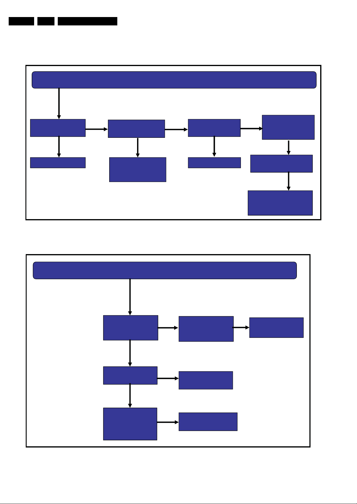
Figure 5-4 Picture okay, no sound.
Figure 5-5 No colour.
18520_206_090313.eps
090313
Picture OK, No sound
Check the voltage of
U17.8~11,it 24v?
Check
L139,L140
Check the Q24
&,is it OK?
Change the
software of U10 &
U8
Change the U17
Check
U17.24,U17.21,
U17.36 is 3.3V?
No
Check the wave of
I2C&I2S OK?
Yes
Check the voltage of
U17.31 & U17.23,is it OK?
Yes
Yes
Yes
No
Yes
No
No
Check
R & L speaker
No
Change the
software of U10
Check the
L103,L101,R361,R362
18520_207_090313.eps
090313
No colour
Colour system is
Right & another
chann el colo ur is
right ?
Dose the TV
signal too weak?
Check the
voltag e of
Z1.1 OK?
Check
U2 & I2C
Reset
To
Local system
Check
Tuner Input
cable & antenna
Check E2PROM
U21
Yes
NO
NO
No
YES
YES
Fine Frequency
YES
Service Modes, Error Codes, and Fault Finding
EN 18 TCM3.1L LA5.
2009-Jun-05
5.7 Software Upgrading
5.7.1 Introduction
It is possible for the user to upgrade the main software via the
USB port. A description on how to upgrade the main software
can be found in the DFU and below.
5.7.2 Main Software Upgrade
In “normal” conditions, so when there is no major problem with
the TV, the main software and the default software upgrade
application can be upgraded with the “upgrade.bin”. This can
also be done by the consumers themselves via the Software
Update Assistant in the user menu (see DFU), but they will
have to download their software from the commercial Philips
website.
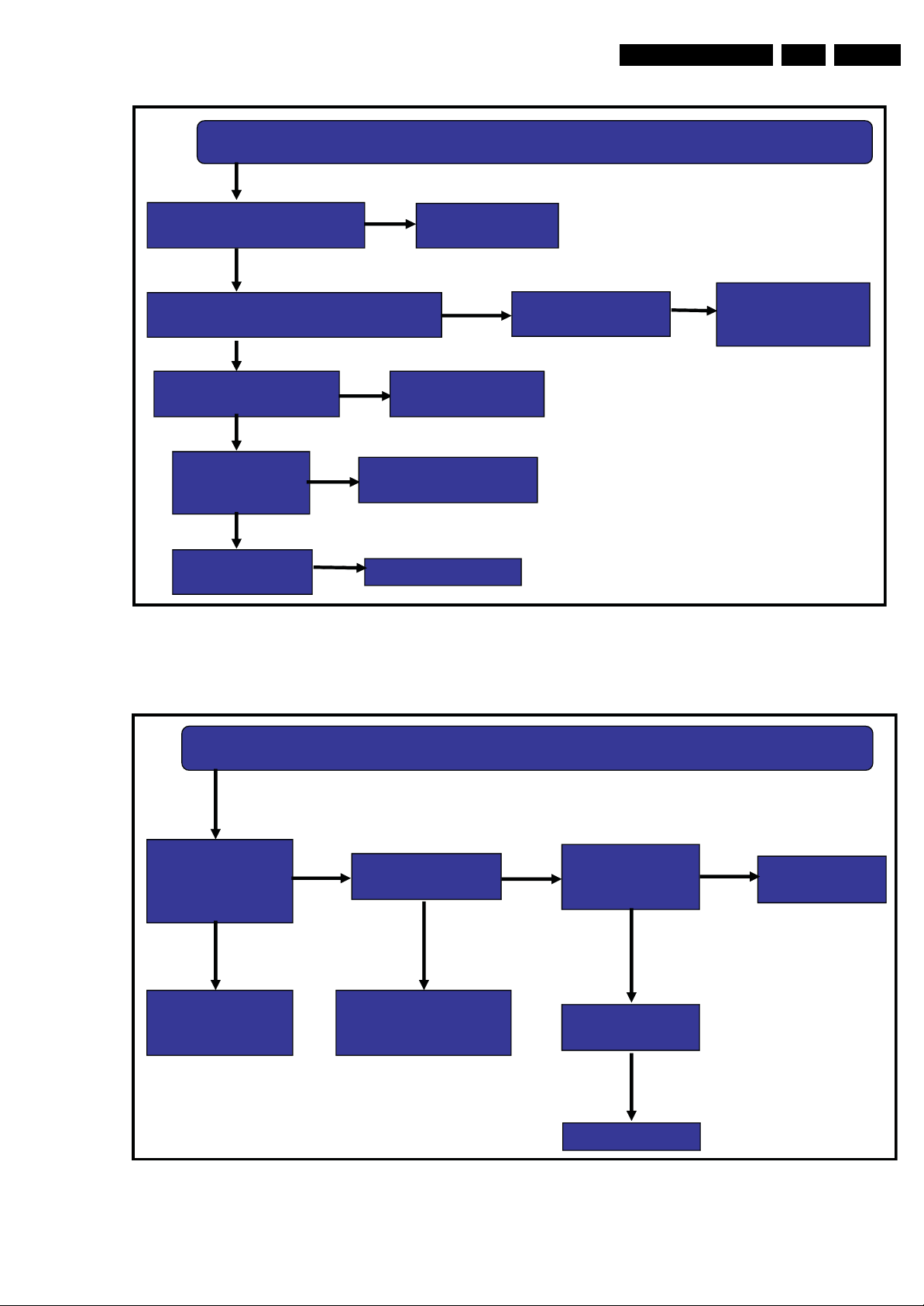
How to upgrade (see also figure 5-9 User SW upgrade
flowchart):
1. Copy the “upgrade.bin” file to the root of the USB stick.
2. Power “off” the TV and remove all memory devices.
3. Insert the USB stick that contains the downloaded software
upgrade.
4. Switch “on” the TV, and activate the Main menu with the
“Menu/House” key on the remote control.
5. In the Main menu, go to the “Software update” item.
6. Press “OK” key to go to the submenu.
7. Select “Local updates” in the submenu and press the “OK”
key to enter the Software Update application.
8. You will be prompted to cancel or to proceed with the
software updating.
9. To proceed, select “Update” and press the “OK” key to
enter the next menu. In the next menu select “Start” and
press “OK” key to start the software update.
10. Upgrading will now begin and the progress of the updating
will be displayed. After the software updating is completed,
the TV will automatically restart.
5.7.3 Stand-by Software Upgrade
In this chassis it is not possible to upgrade the Stand-by
software via a USB stick or ComPair. Please order a pre-
programmed device via the Philips Spare Part web portal.
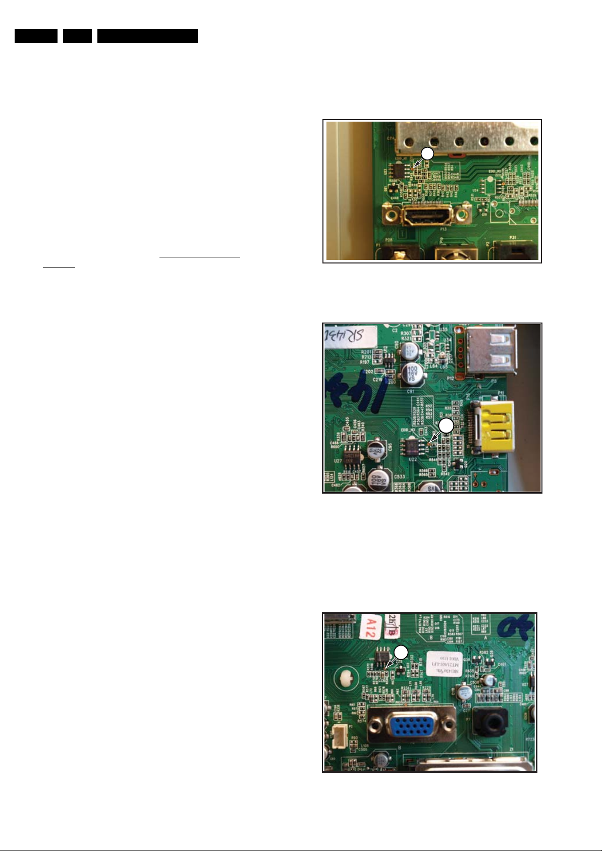
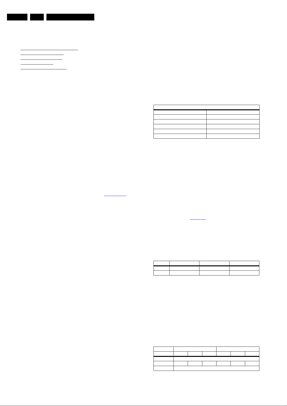
5.7.4 Upgrade HDMI EDID NVM
To upgrade the HDMI EDID, pin 7 of the EDID NVM [1] has to
be short circuited to ground. See ComPair for further
instructions.
Figure 5-6 HDMI-1 EDID NVM
Figure 5-7 HDMI-side EDID NVM
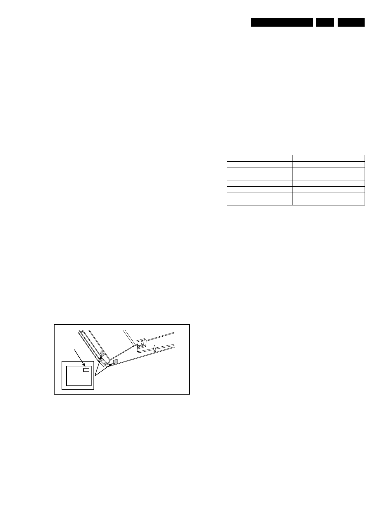
5.7.5 Upgrade VGA EDID NVM
To upgrade the VGA EDID NVM, pin 7 of the EDID NVM [2] has
to be short circuited to ground. See ComPair for further
instructions.
Figure 5-8 VGA EDID NVM
18520_208_090313.eps
090313
1
18520_210_090313.eps
090313
1
18520_209_090313.eps
090313
2

Service Modes, Error Codes, and Fault Finding
EN 19TCM3.1L LA 5.
2009-Jun-05
5.7.6 Main SW upgrade flowchart.
Figure 5-9 User SW upgrade flowchart
18520_215_090325.eps
090325
A newer version of software is deceted.
Do you want to update?
UpgradeCancel
An equal/older version of software is
detected .
Do you want to proceed?
Note: Should be done only if necessary.
UpgradeCancel
Layout 1
Layout 2
Power off the set
Plug-in the USB stick
Enter into Setup Menu and active
local upgrades
Valid auto-run file?
Is US B file ver sion >
set SW
Is US B file ver sion <=
set SW
End
Y
N
Y
N
N
Display U SB sw
newer than the TV
sw.P ro mpt use r to
com firm
Y
Display U SB sw
equal/older than the
TV sw.Prom pt u ser to
com firm
Y
Power on the set
De tect U SB þbreak inÿand
check a utorun file
Please donÿt shut off the power
The software update may takes 3 to 5
minutes
Erasing...
Please donÿt shut off power
The software update may takes 3 to 5
minutes
Upgrading...18%
Layout 3
Layout 4
Proceed?
See Layout 1
See Layout 2
Set process with
sw upgrade
Succe ssful ?
TV auto restar t
the set, prompt
user to r em ove
USB
N
END
Y
If power drop
dur ing th e
upgrade
procedure,don’t
rem ove the U SB
portable memory
TV will
continu e the
upgrade as
soon as power
com es back .
See Layout 3 See Layout 4
Power on TV
Va lid a u to - run
file
Y
N
TV auto erase
and upgrade
softw ar e
Display
upgrade
progress
YN
Prompt user to
try again
Software update
failed! Would you
like to try again
Layout 5
See Layout 5
Retry?
N
Y
Alignments
EN 20 TCM3.1L LA6.
2009-Jun-05
6. Alignments
Index of this chapter:
6.1 General Alignment Conditions
6.2 Hardware Alignments
6.3 Software Alignments
6.4 Option Settings
6.5 Reset of Repaired SSB
6.1 General Alignment Conditions
Perform all electrical adjustments under the following
conditions:
• Power supply voltage (depends on region):
– AP-NTSC: 120 VAC or 230 V
AC
/ 50 Hz (± 10%).
– AP-PAL-multi: 120 - 230 V
AC
/ 50 Hz (± 10%).
– EU: 230 V
AC
/ 50 Hz (± 10%).
– LATAM-NTSC: 120 - 230 V
AC
/ 50 Hz (± 10%).
– US: 120 V
AC
/ 60 Hz (± 10%).
• Connect the set to the mains via an isolation transformer
with low internal resistance.
• Allow the set to warm up for approximately 15 minutes.
• Measure voltages and waveforms in relation to correct
ground (e.g. measure audio signals in relation to
AUDIO_GND).
Caution: It is not allowed to use heat sinks as ground.
• Test probe: Ri > 10 MΩ, Ci < 20 pF.
• Use an isolated trimmer/screwdriver to perform
alignments.
6.1.1 Alignment Sequence
• First, set the correct options: see also section Option codes
• Warming up (>15 minutes).
• Start the alignments.
6.2 Hardware Alignments
Not applicable.
6.3 Software Alignments
Put the set in SAM mode (see chapter 5. Service Modes, Error
Codes, and Fault Finding). The SAM menu will now appear on
the screen. Select the appropriate alignment and go to one of
the sub menus with the “arrow right” button. The alignments are
explained below.
The following items can be aligned:
• Tuner AGC.
• White point.
• ADC calibration of VGA and YPbPr inputs.
To store the data:
• When displayed, select “Store” in the related sub menu and
press the “OK” button on the RC. Screen text will change
from “DO” to “OK”
• Press the MENU/House button on the RC.
• Switch the set to Stand-by mode.
For the next alignments, supply the following test signals via a
video generator to the RF input:
• EU/AP-PAL models: a PAL B/G TV-signal with a signal
strength of at least 1 mV and a frequency of 475.25 MHz
• US/AP-NTSC models: an NTSC M/N TV-signal with a
signal strength of at least 1 mV and a frequency of 61.25
MHz (channel 3).
• LATAM models: an NTSC M TV-signal with a signal
strength of at least 1 mV and a frequency of 61.25 MHz
(channel 3).
6.3.1 Tuner AGC (RF AGC Take Over Point Adjustment)
Purpose: To keep the tuner output signal constant as the input
signal amplitude varies.
The AGC alignment is done automatically (standard value:
“12”). Store settings and exit SAM
6.3.2 White Point
• Press the “Menu/Home” button on the RC, and then select
“Picture”. Set the picture settings as follows:
• Activate SAM mode and select “RGB Align”.
White point alignment LCD screens:
• Use a 100% white screen on HDMI-1 as input signal and
set the following values:
– “Colour temperature”: “Cool”.
– All “R/G/B_Gain” values to: “127”.
– All “R/G/B_Offset” values to: “240”.
In case colour analyser can be used:
• Measure with a calibrated contactless colour analyser in
the centre of the screen. Consequently, the measurement
needs to be done in a dark environment.
• Adjust the correct x,y coordinates by means of decreasing
the value of one or two other white points to the correct x,y
coordinates (see Table 6-1
). Tolerance dx, dy: ± 0.004.
Only the “Cool” colour temperature needs to adjust.
• When finished, select “Store” in the “RGB Align” sub menu,
and press “OK” on the RC to store the aligned values to the
NVM.
• Restore the initial picture settings after the alignments.
Table 6-1 White D alignment values
In case no colour analyser is available, the default values
can be used. This is the next best solution. The default values
are average values coming from production.
• Select the “Cool” colour temperature.
• Set the RED, GREEN and BLUE default values according
to the values in the “White tone default settings” table.
• When finished, select “Store” in the “RGB Align” sub menu,
and press “OK” on the RC to store the aligned values to the
NVM.
• Restore the initial picture settings after the alignments.
Table 6-2 White tone default settings
(*) Default values were not available at the time of publishing.
They will be published as soon as they become available.
Picture Setting
Smart Picture Personal
Colour Temperature Cool
Dynamic Contrast Off
Dynamic Backlight Off
Colour Enhancement Off
Light Sensor Off
Value Cool (11000K) Normal (9000K) Warm (6500K)
x 0.278 0.289 0.314
y 0.278 0.291 0.319
White Tone 32" 42"
Colour Temp R G B R G B
Normal auto adjusted
Cool
175 151 168 176 150 170
Warm auto adjusted
Alignments
EN 21TCM3.1L LA 6.
2009-Jun-05
6.3.3 Auto ADC
Purpose: For correct gray- and colour scale values of the VGA
and YPbPr inputs.
How to align the VGA/PC input:
1. Provide a 1024 × 768 @ 60 Hz test signal with White/
Black squares to the VGA input.
2. Select “Auto ADC” in the SAM menu.
3. Press the “Arrow right” button on the RC.
4. Press “OK” on the RC.
5. Wait until OSD shows “Auto ADC - OK”.
How to align the YPbPr inputs (CVI-1 and CVI-2):
1. Provide a 1024 × 768 @ 60 Hz test signal with 100% 8
step colour bar to the YPbPr input.
2. Rest is the same as for the VGA input.
6.4 Option Settings
6.4.1 Introduction
The microprocessor communicates with a large number of I
2
C
ICs in the set. To ensure good communication and to make
digital diagnosis possible, the microprocessor has to know
which ICs to address, and what brand and type of display is
used.
6.4.2 Display code
Changing the display option code via a standard RC
Key in the code “0 6 2 5 9 8 MENU x x x” (where x x x is the 3
digit decimal display code of the used display *).
Tips:
• Keep the RC close to the IR receiver, and make sure the
LED blinks when entering a code.
• Key in all codes in one sequence, without pauses.
If the above action is successful, the front LED will go out as an
indication that the RC sequence was correct. After the display
option is changed in the NVM, the TV will go to the Stand-by
mode. If the NVM was corrupted or empty before this action, it
will be initialized first (loaded with default values). This
initializing can take up to 20 seconds.
Figure 6-1 Location of Display Option Code sticker
(*) This display code can be found on the side sticker (see
figure above) and/or on the rear sticker.
6.4.3 Option codes
Select this sub menu to set all options at once by selecting the
correct model number. The so-called “Project ID” represents a
number of different options, all related to that model number.
By toggling the “arrow left/right” buttons on the RC, the correct
model number can be selected.
• After changing the option (or Project ID), save it by leaving
the sub menu via the “Menu/House” button on the RC.
• The new option setting is only active after the TV is
switched “off/on” with the mains switch (the NVM is then
read again).
6.5 Reset of Repaired SSB
When a repaired SSB will be used in an other TV, it is very
important that the correct info is written into the NVM w.r.t.
12NC of the SSB, production serial number of the TV, 12NC of
display and PSU, etc.
To set all this, the ComPair tool can be used, or the NVM can
be edited directly via the NVM editor (in SAM). Find below the
addresses of these items. Use the decimal values.
In case of a display replacement, reset the “Operation hours” to
“0”, or to the operation hours of the replacement display.
Table 6-3 NVM addresses of “reset items”
PHILIPS
MODEL:
32PF9968/10
PROD.SERIAL NO:
AG 1A0620 000001
040
39mm
27mm
(CTN Sticker)
Display Option
Code
E_06532_038.eps
240108
Item NVM Address (decimal)
Display code 3195
Production serial number 3196 - 3211 (16 bytes)
SSB 12NC 3212 - 3225 (16 bytes)
Display 12NC 3228 - 3243 (16 bytes)
PSU 12NC 3244 - 3259 (16 bytes)
Model Number 3260 - 3275 (16 bytes)
Operational hours not available at the time of publishing
Loading...