


 Loading...
|
SRF-S54/S56 |
SERVICE MANUAL |
E Model |
Ver 1.0 2002.10 |
Chinese Model |
|
Photo: SRF-S56
SPECIFICATIONS
Frequency range
87.5 - 108 MHz
Output
i (stereo earphones) jack (ø 3.5 mm stereo minijack) load impedance 16 1
Power output
4.5 mW + 4.5 mW (at 10% hamonic distortion)
Power requirements
1.5 V DC, one R03 (size AAA) battery
Dimensions
Approx. 33.7 × 75.3 × 16 mm (w/h/d) (Approx. 1 3/8 × 3 × 5/8 inches) not incl. projecting parts and controls
Approx. 34.9 × 76.3 × 20 mm (w/h/d) (Approx. 1 7/16 × 3 1/8 × 13/16 inches) incl. projecting parts and controls
Mass
Approx. 46.6 g (1.7 oz ) incl. a battery and stereo earphones
Supplied accessory
Stereo earphones (1)
Design and specifications are subject to change without notice.
FM STEREO RADIO
9-874-198-01 Sony Corporation
2002J0500-1 Personal Audio Company
C 2002.10 Published by Sony Engineering Corporation
SRF-S54/S56
TABLE OF CONTENTS
1. GENERAL .................................................................. |
3 |
2.DISASSEMBLY
2-1. |
Disassembly Flow ........................................................... |
4 |
2-2. |
Cabinet (Rear) Block, Knob (ST) ................................... |
4 |
2-3. |
MAIN Board ................................................................... |
5 |
3. |
ASSEMBLY |
|
3-1. |
How to Install Gear (Tuning Capacitor) ......................... |
6 |
4. |
ELECTRICAL ADJUSTMENTS ........................ |
7 |
5.DIAGRAMS
5-1. |
Block Diagram ............................................................... |
8 |
5-2. Note for Printed Wiring Board and |
|
|
|
Schematic Diagram ......................................................... |
9 |
5-3. |
Printed Wiring Board ..................................................... |
10 |
5-4. |
Schematic Diagram ........................................................ |
11 |
6. |
EXPLODED VIEWS ............................................... |
12 |
7. |
ELECTRICAL PARTS LIST .............................. |
12 |
Notes on chip component replacement
•Never reuse a disconnected chip component.
•Notice that the minus side of a tantalum capacitor may be damaged by heat.
2
SECTION 1 |
SRF-S54/S56 |
This section is extracted from |
|
GENERAL |
instruction manual. |
|
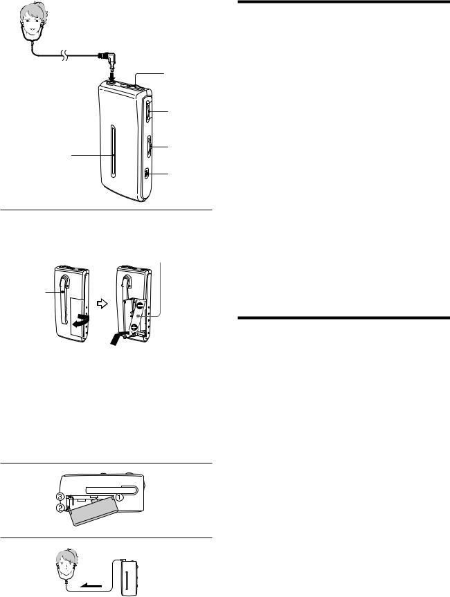
i (stereo earphones) jack Prise i (écouteurs stéréo) Stereo-Ohrhörerbuchse i Toma i (auriculares estéreo)
i (stereo oortelefoon) aansluiting
|
OFF/ON/ |
|
|
MEGABASS |
|
|
TUNE |
|
Dial scale |
VOLUME |
|
|
||
Voyant de |
|
|
syntonisation |
MONO/ST |
|
Frequenzanzeige |
||
|
||
Dial |
|
|
Afstemschaal |
|
|
Rear |
R03 (size AAA) x 1 |
|
AArrière |
||
R03 (format AAA) x 1 |
||
Rückseite |
||
R03 (Größe AAA) x 1 |
||
Posterior |
||
R03 (tamaño AAA) x 1 |
||
Achter |
||
R03 (AAA) x 1 |
||
|
||
Clip* |
|
|
Pince* |
|
|
Klammer* |
|
|
Gancho* |
|
Insert the # side of the battery first. Introduisez d’abord le pôle négatif # de la pile.
Legen Sie die Batterie mit dem Minuspol # zuerst ein. Inserte el polo negativo de la pila primero.
Breng de # kant van de batterij eerst in.
*Press the top of the clip to open.
*Appuyez sur le haut de la pince pour ouvrir. *Drücken Sie zum Öffnen oben auf die Klammer. *Presione la parte superior del gancho para abrirlo. *Druk op de bovenkant van de clip om deze te openen.
B
C
Installing the Battery
(See Fig. A)
1Open the battery compartment lid at the rear of the radio.
2Insert one R03 (size AAA) battery (not supplied) with the 3 and # marks aligned correctly.
3Close the battery compartment lid.
Battery life (approx. hours) |
(JEITA*) |
Using Sony alkaline LR03 (size AAA)battery |
44 |
Using Sony R03 (size AAA)battery |
19 |
*Measured by JEITA (Japan Electronics and Information Technology Industries Association) standards. The actual battery life may vary depending on the circumstance of the unit.
When to replace the battery
Replace the battery when the sound becomes weak or distorted.Remove the old battery and insert a new one.
Notes on battery
•Do not charge the drybattery.
•Do not carry the dry battery with coins or other metallic objects. It can generate heat if the positive and negative terminals of the battery are accidentally contacted by a metallic object.
•When you are not going to use the unitfor a long time, remove the battery to avoid damage from battery leakage and corrosion.
If the battery compaertment lid comes off (See Fig. B)
The battery compartment lid is designed to come off when opened with excessive force. To putit back on, see the illustration.
1Insert the righthook of the lidinto the righthole in the unit.
2Hang the left hook on the left part of the compartment where the lid fits.
3Slide the left hook towardthe left hole in the unit.
Operating the Radio
1Connect the suppliedstereo earphones to i (stereo earphones) jack.
2Set OFF/ON/MEGABASS to ON to turnon the radio.
3Turn TUNE to tune in to a station.
4Adjust VOLUME.
To turn off the radio
Set OFF/ON/MEGABASS to OFF.
To Improve the Reception (See Fig. C)
Extend the stereo earphones cord whichfunctions as an FM antenna.
When listeningto the stereo reception, normallyset MONO/ST to ST (stereo)*. If the stereo reception is poor, set MONO/ST to MONO. Although the sound will not be heard in stereo, noise will be reduced.
*You will hear the sound in stereo only when the program of the station that you are tuned into is in stereo.
To Enjoy Powerful Bass Sound
Set OFF/ON/MEGABASS to MEGABASS to emphasize bass sound.
3

SRF-S54/S56
SECTION 2
DISASSEMBLY
• This set can be disassembled in the order shown below.
2-1. DISASSEMBLY FLOW
SET
2-2. CABINET (REAR) BLOCK, KNOB (ST)
(Page 4)
2-3. MAIN BOARD (Page 5)
Note: Follow the disassembly procedure in the numerical order given.
2-2. CABINET (REAR) BLOCK, KNOB (ST)
1two screws (B1.7 × 8)
4 claw
5 cabinet (rear) block
3 two claws
6 knob (ST)
knob (ST)
slide switch (S2)
Note: When installing knob (ST), 2 claw connect with slide switch
(STEREO/MONO) (S2).
4
SRF-S54/S56
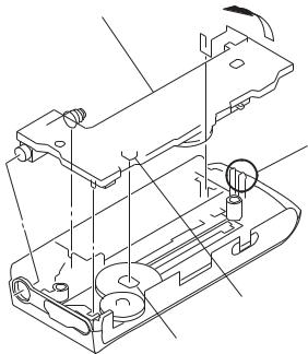
2-3. MAIN BOARD
3 main board |
1 |
2 claw
shaft
(tuning capacitor)
hole
(gear (tuning capacitor))
5
Loading...