


 Loading...
3-620-374-11 (1)
Network Camera
User’s Guide
Software Version 1.0
SNC-RZ30N/RZ30P
© 2002 Sony Corporation
Owner's Record
The model and serial numbers are located at the bottom. Record these numbers in the spaces provided below. Refer to these numbers whenever you call upon your Sony dealer regarding this product.
Model No. ____________________
Serial No. ____________________
WARNING
To prevent fire or shock hazard, do not expose the unit to rain or moisture.
For AC Adaptor
To avoid electrical shock, do not open the cabinet. Refer servicing to qualified personnel only.
Important
Nameplate is located on the bottom.
For customers in the U.S.A. (SNC-RZ30N only)
This equipment has been tested and found to comply with the limits for a Class B digital device, pursuant to Part 15 of the FCC Rules. These limits are designed to provide reasonable protection against harmful interference in a residential installation. This equipment generates, uses, and can radiate radio frequency energy and, if not installed and used in accordance with the instructions, may cause harmful interference to radio communications. However, there is no guarantee that interference wll not occur in a particular installation. If this equipment does cause harmful interference to radio or television reception, which can be determined by turning the equipment off and on, the user is encouraged to try to correct the interference by one or more of the following measures:
–Reorient or relocate the receiving antenna.
–Increase the separation between the equipment and receiver.
–Connect the equipment into an outlet on a circuit different from that to which the receiver is connected.
–Consult the dealer or an experienced radio/TV technician for help.
You are cautioned that any changes or modifications not expressly approved in this manual could void your authority to operate this equipment.
The shielded interface cable recommended in this manual must be used with this equipment in order to
comply with the limits for a digital device pursuant to Subpart B of Part 15 of FCC Rules.
If you have any questions about this product, you may call:
Sony's Business Information Center (BIC) at 1-800-686-7669
or Write to: Sony Customer Information Services Center
6900-29, Daniels Parkway, PMB 330 Fort Myers, Florida 33912
Declaration of Conformity
Trade Name: |
SONY |
Model No: |
SNC-RZ30N |
Responsible Party: Sony Electronics Inc. |
|
Address: |
680 Kinderkamack Road, Oradell, |
|
NJ 07649 USA |
Telephone No: |
201-930-6972 |
This device complies with part 15 of the FCC Rules. Operation is subject to the following two conditions:
(1)this device may not cause harmful interference, and
(2)this device must accept any interference received, including interference that may cause undesired operation.
Voor de klanten in Nederland
•Dit apparaat bevat een vast ingebouwde batterij die niet vervangen hoeft te worden tijdens de levensduur van het apparaat.
•Raadpleeg uw leverancier indien de batterij toch vervangen moet worden. De batterij mag alleen vervangen worden door vakbekwaam servicepersoneel.
•Gooi de batterij miet weg maar lever deze in als klein chemisch afval (KCA).
•Lever het apparaat aan het einde van de levensduur in voor recycling, de batterij zal dan op correcte wijze verwerket worden.
2

NOTICE TO USERS
© 2002 Sony Corporation. All rights reserved. This manual or the software described herein, in whole or in part, may not be reproduced, translated or reduced to any machine readable form without prior written approval from Sony Corporation.
SONY CORPORATION PROVIDES NO WARRANTY WITH REGARD TO THIS MANUAL, THE SOFTWARE OR OTHER INFORMATION CONTAINED HEREIN AND HEREBY EXPRESSLY DISCLAIMS ANY IMPLIED WARRANTIES OF MERCHANTABILITY OR FITNESS FOR ANY PARTICULAR PURPOSE WITH REGARD TO THIS MANUAL, THE SOFTWARE OR SUCH OTHER INFORMATION. IN NO EVENT SHALL SONY CORPORATION BE LIABLE FOR ANY INCIDENTAL, CONSEQUENTIAL OR SPECIAL DAMAGES, WHETHER BASED ON TORT, CONTRACT, OR OTHERWISE, ARISING OUT OF OR IN CONNECTION WITH THIS MANUAL, THE SOFTWARE OR OTHER INFORMATION CONTAINED HEREIN OR THE USE THEREOF.
Sony Corporation reserves the right to make any modification to this manual or the information contained herein at any time without notice.
The software described herein may also be governed by the terms of a separate user license agreement.
“Memory Stick” is a trademark of Sony Corporation. Microsoft, Windows, Internet Explorer and MS-DOS are registered trademarks of Microsoft Corporation in the United States and/or other countries.
Netscape and Navigator are registered trademarks of Netscape Communications Corporation in the U.S. and other countries.
Java is a trademark of Sun Microsystems, Inc. in the United States and other countries.
MMX and Pentium are registered trademarks of Intel Corporation or its subsidiaries in the United States and other countries.
All other company and product names are trademarks or registered trademarks of the respective companies or their respective makers.
3

Table of Contents |
|
Overview |
|
How to Use This User’s Guide .............................. |
6 |
Precautions ............................................................. |
6 |
Operating Precautions ........................................ |
6 |
Operating the Camera |
|
Logging in to Homepage — Welcome Page ........ |
7 |
Logging in as a User .......................................... |
7 |
Logging in as Administrator .............................. |
7 |
About Viewers .................................................... |
8 |
Configuration of Main Viewer Page .................... |
9 |
Menu Section ..................................................... |
9 |
Image Control Section ..................................... |
10 |
Controlling the Monitor Image .......................... |
11 |
Operating the Camera ........................................ |
11 |
Panning and Tilting .......................................... |
11 |
Zooming ........................................................... |
12 |
Focusing ........................................................... |
12 |
Moving the Camera to the Preset Position ....... |
13 |
Controlling the Application Manually .............. |
13 |
Sending a Still Image File to an FTP Server .... |
13 |
Sending a Still Image via E-mail ..................... |
13 |
Recording a Still Image on an ATA Memory Card |
|
or the Built-in Memory of the Camera ........... |
14 |
Controlling Alarm Output ................................ |
14 |
Capturing a Monitor Image ............................... |
14 |
Administrating the Camera |
|
Configuration of Administrator Menu Page ..... |
15 |
Configuring the System — System setting Page 16 |
|
System setting Section ..................................... |
16 |
Date time setting Section ................................. |
17 |
Setting the Camera — Camera setting Page .... 19 |
|
Upper Half of Camera setting Page ................. |
19 |
Lower Half of Camera setting Page ................. |
20 |
Configuring the Network |
|
— Network (Ethernet) setting Page ................... |
22 |
Setting the User — User setting Page ................ |
23 |
Setting the Security — Security setting Page .... |
24 |
Activating/Deactivating the Security Function |
|
— Security usage setting Page ....................... |
24 |
Setting the Security Function |
|
—Securing setting Page ................................. |
24 |
Setting the Camera Position and Action |
|
— Preset position setting Page ........................... |
25 |
Storing the Pan, Tilt and Zoom Positions |
|
— Position preset Section .............................. |
25 |
Moving the Camera to the Preset Position by the |
|
Alarm — Position at alarm Section ................ |
26 |
Checking the Preset Position Settings |
|
— Preset position table Section ...................... |
26 |
Programming the Tour |
|
— Tour setting Section ................................... |
26 |
Checking the Tour Settings |
|
— Tour table Section ...................................... |
27 |
Activating the Tour— Tour selection Section ... |
27 |
Sending Images to FTP Server |
|
— FTP client setting Page ................................... |
28 |
Activating/Deactivating the FTP Client Function |
|
— FTP client usage setting Page .................... |
28 |
Setting the FTP Client Function |
|
— FTP client setting Page .............................. |
28 |
Alarm mode setting Section ............................. |
29 |
Periodical sending mode setting Section .......... |
29 |
Operating the Digest Viewer ............................ |
30 |
Downloading Images from the Camera |
|
— FTP server setting Page .................................. |
31 |
Activating/Deactivating the FTP Server Function |
|
— FTP server usage setting Page ................... |
31 |
Setting the FTP Server Function |
|
— FTP server setting Page ............................. |
31 |
Sending an Image via E-mail |
|
— SMTP setting Page .......................................... |
32 |
Activating/Deactivating the SMTP Function |
|
— SMTP usage setting Page .......................... |
32 |
Setting the SMTP Function |
|
— SMTP setting Page .................................... |
32 |
Alarm mode setting Section ............................. |
33 |
Periodical sending mode setting Section .......... |
33 |
Setting the Alarm Out 1 or 2 |
|
— Alarm out 1 or 2 setting Page ........................ |
34 |
Activating/Deactivating the Alarm Out 1 Function |
|
— Alarm out 1 usage setting Page ................. |
34 |
Setting the Alarm Out 1 Function |
|
— Alarm out 1 setting Page ........................... |
34 |
Alarm mode setting Section ............................. |
34 |
Timer mode setting Section .............................. |
35 |
Recording Images in Memory |
|
— Image memory setting Page ........................... |
35 |
Activating/Deactivating the Image Memory |
|
Function |
|
— Image memory usage setting Page ............ |
35 |
Recording an Image in the Selected Memory |
|
— Image memory setting Page ...................... |
36 |
Alarm mode setting Section ............................. |
36 |
Periodical recording mode setting Section ....... |
37 |
Directory Structure of Image Memory ............. |
38 |
Setting the Alarm Buffer |
|
— Alarm buffer setting Page .............................. |
38 |
Communicating Data via Serial Port |
|
— Serial setting Page ........................................... |
39 |
Setting the Schedule — Schedule setting Page .. |
40 |
Setting the Activity Detection Function |
|
— Activity detection setting Page ....................... |
40 |
4 Table of Contents

Setting the Activity Detection Area ................. |
40 |
Showing the Pop-up |
|
— Pop-up setting Page ........................................ |
41 |
Others |
|
Using the Supplied Setup Program .................... |
42 |
Assigning the IP Address Using the Setup |
|
Program .......................................................... |
42 |
Changing the Communication Bandwidth ....... |
43 |
Setting the Date and Time ................................ |
43 |
Rebooting the Camera ...................................... |
44 |
Assigning the IP Address to the Camera Using |
|
ARP Commands .................................................. |
44 |
Table of Contents |
5 |
|
|

Overview
Overview
How to Use This User’s Guide
This User’s Guide explains how to operate the SNCRZ30N/RZ30P Network Camera from a computer. The User’s Guide is written to be read on the computer display.
As this section gives tips on using the User’s Guide, read it before you operate the camera.
Jumping to the related page
When you read the User’s Guide on the computer display, click on the sentence to jump to the related page.
Software display examples
Note that the displays shown in the User’s Guide are explanatory examples. Some displays may be different from the ones which appear as you operate the application software.
Printing the User’s Guide
Depending on your system, certain displays or illustrations in the User’s Guide, when printed out, may differ from those as portrayed on your screen.
Installation Manual (printed matter)
The supplied Installation Manual describes the names and functions of parts and controls of the Network Camera, connecting examples and how to set up the camera. Be sure to read the Installation Manual before operating.
Precautions
This Sony product has been designed with safety in mind. However, if not used properly electrical products can cause fires which may lead to serious body injury. To avoid such accidents, be sure to heed the following.
Heed the safety precautions
Be sure to follow the general safety precautions and the “Operating Precautions.”
In case of a breakdown
In case of system breakdown, discontinue use and contact your authorized Sony dealer.
In case of abnormal operation
•If the unit emits smoke or an unusual smell,
•If water or other foreign objects enter the cabinet, or
•If you drop the unit or damage the cabinet:
1 Disconnect the camera cable and the connecting cables.
2 Contact your authorized Sony dealer or the store where you purchased the product.
Operating Precautions
Operating or storage location
Avoid operating or storing the camera in the following locations:
•Extremely hot or cold places (Operating temperature: 0°C to +40°C [32°F to 104°F])
•Exposed to direct sunlight for a long time, or close to heating equipment (e.g., near heaters)
•Close to sources of strong magnetism
•Close to sources of powerful electromagnetic radiation, such as radios or TV transmitters
Transportation
When transporting the camera, repack it as originally packed at the factory or in materials of equal quality.
Cleaning
•Use a blower to remove dust from the lens or optical filter.
•Use a soft, dry cloth to clean the external surfaces of the camera. Stubborn stains can be removed using a soft cloth dampened with a small quantity of detergent solution, then wipe dry.
•Do not use volatile solvents such as alcohol, benzene or thinners as they may damage the surface finishes.
6 How to Use This User’s Guide / Precautions
Operating the Camera
The Operating the Camera section explains how to monitor the image from the camera using the Web browser. For setting the camera, see “Administrating the Camera” on page 15.
Logging in to Homepage
— Welcome Page
Logging in as a User
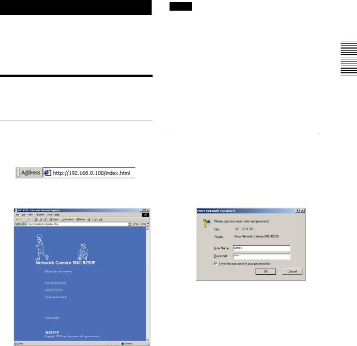
1 Start the web browser on the computer and type the IP address of the camera you want to monitor.
The welcome page of Network Camera SNCRZ30 is displayed.
2 Click to select the viewer.
You can select the viewer from among Java applet viewer, ActiveX viewer and Server push viewer, whichever is suitable for your system environments and usage.
For details, see “About Viewers” on page 8. When you have selected the viewer, the main viewer page appears (see page 9).
Note
To operate the welcome page correctly, set the security level of the Internet Explorer to Medium or lower, as follows:
1 Select Tool from the menu bar of Internet Explorer, then select Internet Options and Security tab in sequence.
2 Click the Internet icon (when using the camera via the Internet) or Local intranet icon (when using the camera via a local network).
3 Set the slider to Medium or lower. (If the slider is not displayed, click Default Level.)
Logging in as Administrator
If you log in the camera as the Administrator, you can perform all the settings provided with the software. The Administrator may be logged in at any time, regardless of the number of the users being accessed.
1 Click Administrator on the welcome page. The login page appears.
2 Enter the user name and password for Administrator, then click OK.
The user name “admin” and the password “admin” are set as default settings for the Administrator. You can change them on the User setting page in the Administrator menu (see page 23).
Camera the Operating
Logging in to Homepage — Welcome Page |
7 |
|
|
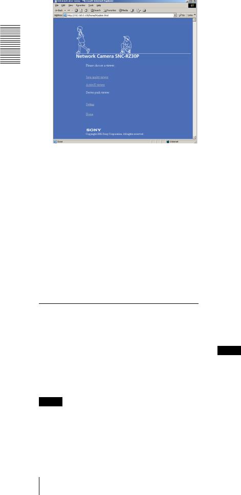
The welcome page is changed to that for
Administrator.
Camera the Operating
3 Select the viewer.
You can select the viewer from among Java applet viewer, ActiveX viewer and Server push viewer, whichever is suitable for your system environments and usage.
For details, see “About Viewers” on page 8. When you have selected the viewer, the main viewer page appears (see page 9).
Other functions on the welcome page for Administrator
Setting
Click to display the Administrator menu (see page 15).
Home
Click to return to the normal welcome page.
About Viewers
You can select one of the following three viewers.
Java applet viewer
The Java applet viewer operates on Internet Explorer or Netscape.
It displays the main viewer page using Java.
With this viewer, you can use all the functions provided with this software.
Notes
•The frame rate is lower than that for the other viewers.
•If the viewer does not operate correctly, install or activate Java as follows:
If you are using Internet Explorer
Select Tool from the menu bar of Internet Explorer, then select Internet Option and the Advanced tab in sequence, and check JIT compiler for virtual machine enabled (requires restart). Then restart Internet Explorer.
If you are going to install Netscape
Install Java in the process of Netscape installation, following the instructions of the installer.
After installing, select Edit from the menu bar of Netscape, then Setting and Details for category in sequence, and check Activate Java.
If you are using Netscape without Java installed
Install Java from the Plug-in Download Page of Netscape.
If you are using Netscape with Java installed, but the viewer does not operate correctly
Download Java 2 Runtime Environment, Standard Edition (JRE) from Netscape Netcenter or Sun HomePage, and install it following the intructions of the installer. After installing, select Edit from the menu bar of Netscape, then Setting and Details for category in sequence, and check Activate Java.
ActiveX viewer
The ActiveX viewer operates on Internet Explorer. It displays the main viewer page using ActiveX.
With this viewer, you can display images at a high frame rate and use all the functions provided with this software.
ActiveX Control is automatically installed to your computer when you log in the camera using Internet Explorer for the first time.
Server push viewer
The Server push viewer operates on Netscape. When you select this viewer, the main viewer page is
displayed through the Server push technology which the Netscape supports as standard.
This viewer allows image display at a high frame rate.
Notes
•When you use the Server push viewer, the time display, pop-up display and image size selection do not operate. As the image rotation does not operate, the camera image is always upside down when the camera is installed on a desk top.
•If you display a large size image such as VGA with a high frame rate using the Server push viewer, the computer may freeze. Change Frame rate on the main viewer page (see page 11), or Image size on the Camera setting page (see page 19) to match your computer performance.
8 Logging in to Homepage — Welcome Page
Tip
Every page of this software is optimized as display character size Medium for Internet Explorer, or 100% for Netscape.
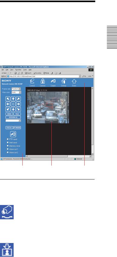
Configuration of Main
Viewer Page
When you select the viewer, the main viewer page is displayed.
This section briefly explains the functions of the parts and controls on the main viewer page. For a detailed explanation on each part or control, see the specified pages.
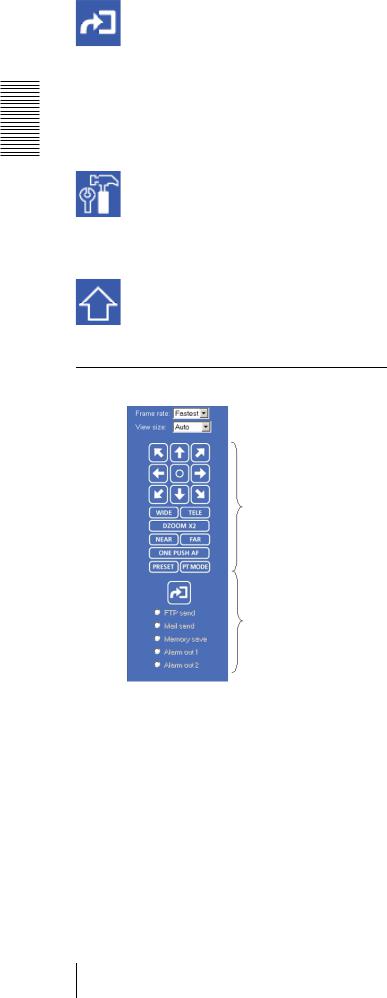
Main viewer page
Camera the Operating
Image control section |
Monitor image |
Menu section |
Menu Section
The available functions are limited by user access right. You can change user access right on the User setting page (see page 23).
Control
Displays the camera control parts on the image control section. (See “Operating the Camera” on page 11.) User access right Level 2 to Level 4 is required for this function.
Capture
Captures a still image shot by the camera and stores it in the computer. (See “Capturing a Monitor Image” on page 14.)
Configuration of Main Viewer Page |
9 |
|
|
Camera the Operating
Trigger
Displays the trigger control parts on the image control section.
By clicking the trigger button, you can control various applications manually. (See “Controlling the Application Manually” on page 13.)
User access right Level 3 or Level 4 is required for this function.
Setting
Displays the Administrator menu. (See “Configuration of Administrator Menu Page” on page 15.)
User access right Level 4 is required for this function.
Home
Displays the Welcome page.
Image Control Section
See “Operating the Camera” on page 11.
Trigger control parts
These parts are displayed when you click Trigger on the menu section. You can output a trigger using these parts. See “Controlling the Application Manually” on page 13.
Camera control parts
Trigger control parts
Frame rate
Selects the frame rate to transmit images. See “Selecting the frame rate” on page 11.
View size
Selects the image size to be displayed. See “Selecting the view size” on page 11.
Camera control parts
These parts are displayed when you click Control on the menu section. You can operate the camera using these parts.
10 Configuration of Main Viewer Page
Controlling the Monitor
Image
You can control the monitor image from the image control section on the main viewer page.
Image control section
Operating the Camera
You can operate the camera from the image control section on the main viewer page.
For this function, user access right Level 2 to Level 4 is required (see page 23).
Click  Control on the menu section to display the camera control parts.
Image control section (camera control parts)
Selecting the frame rate
Click the down-arrow button in the Frame rate box and select the frame rate with which the images are transmitted, from the drop-down list.
You can select the frame rate from among the following: SNC-RZ30N:
1, 2, 3, 4, 5, 6, 8, 10, 15, 20, 25, Fastest
SNC-RZ30P:
1, 2, 3, 4, 5, 6, 8, 12, 16, 20, Fastest
The numbers indicate “FPS” (the number of frames transmitted per second).
With Fastest, the camera transmits the maximum number of frames possible for the connected line. The maximum frame rate is 30 FPS for the SNC-RZ30N and 25 FPS for the SNC-RZ30P.
Note
The frame rate options indicate the maximum number of frames that can be transmitted. The number of frames actually transmitted may vary depending on the network environments and camera settings (image size and image quality settings).
Selecting the view size
Click the down-arrow button in the View size box and select the view size from the drop-down list.
You can select the view size from among the following:
Auto, 640 × 480, 320 × 240, 160 × 120
Auto is determined by the image size specified with Image size on the Camera setting page (see page 19).
Panning and Tilting
You can pan and tilt the camera using the 8-direction arrow buttons or the tablet.
Setting the pan/tilt mode
Click  . Each click alternates the 8-direction arrow mode and the tablet mode.
Panning and tilting using the 8-direction arrow buttons
Observe the monitor image and click the arrow button indicating the direction in which you want to move the camera. The camera moves and the monitor image follows.
Camera the Operating
Controlling the Monitor Image / Operating the Camera |
11 |
|
|
Hold down the arrow button to move the direction of the camera continuously.
Click  to return the camera to the factory-preset default position.
Note
If the Exclusive control mode menu on the System setting page is set to On (see page 17), the remaining operation time is displayed instead of  .
.
Camera the Operating |
Panning and tilting using the tablet |
|
When you click PT MODE, the 8-direction arrow buttons change to a tablet. The tablet represents the monitor image.
A click on the tablet moves the direction of the camera so that the clicked position goes to the center of the monitor image.
If you want to change the direction of the camera further, click on the tablet and drag in the direction in which you want to move the camera. The direction of the camera moves as you drag. Hold down the button to move the direction of the camera continuously.
Notes
•The tablet represents the whole monitor image even when you have trimmed the monitor image using the Area setting menu on the Camera setting page (see page 19).
•If the Exclusive control mode menu on the System setting page is set to On (see page 17), the remaining operation time is displayed on the lower right corner of the tablet.
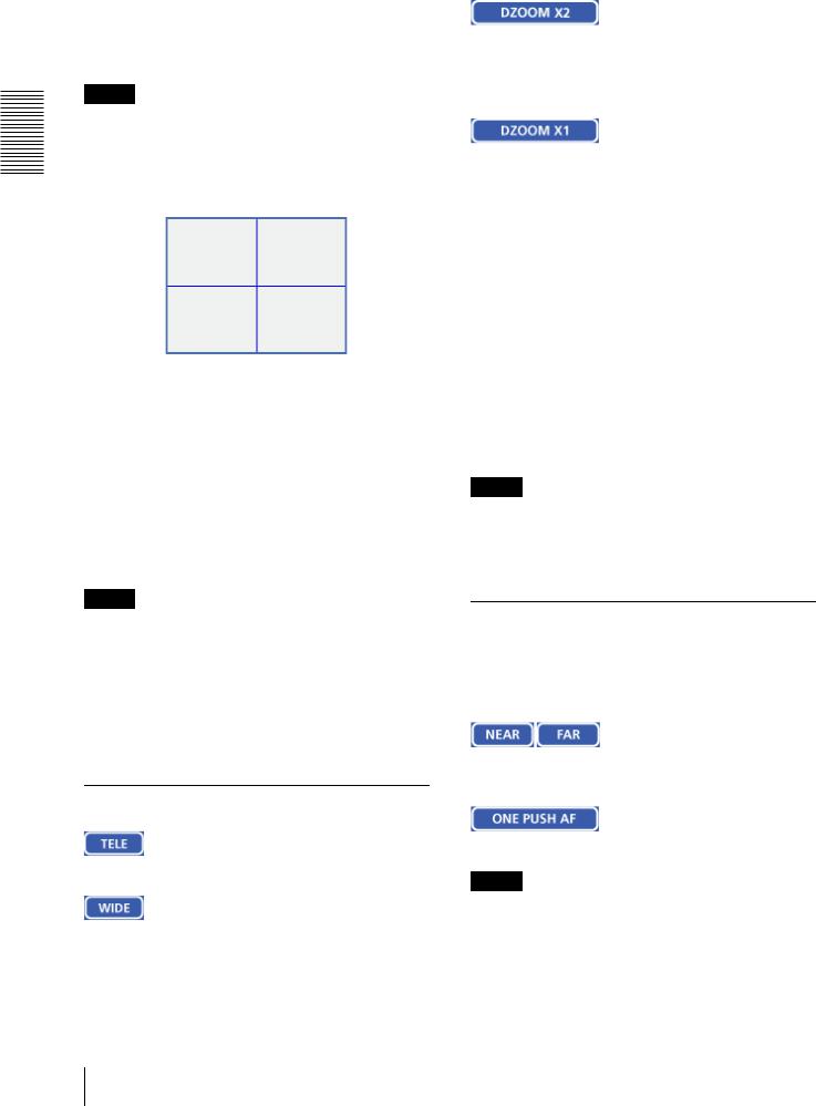
Zooming
CIick to zoom in.
Click to zoom out.
When the Zoom mode menu on the Camera setting page is set to Optical only, clicking this button operates the electronic ×2 zoom.
The button name changes to DZOOM x 1.
When the Zoom mode menu on the Camera setting page is set to Optical only, this button is displayed while the electronic ×2 zoom is operating. Clicking this button cancels the electronic ×2 zoom.
The button name changes to DZOOM x 2.
About the zoom range
When the Zoom mode menu on the Camera setting page is set to Full (see page 20), you can operate highmagnification zoom, optical zoom of × 25 and electronic zoom of × 12, giving × 300 in total. The electronic zoom will operate after the optical zoom.
When the Zoom mode menu is set to Optical only, only optical zoom of × 25 can operate. In this case, you can use an electronic zoom of × 2 by clicking the DZOOM x 2 button. To cancel the electronic zoom, click
DZOOM x 1.
Note
When you have changed the Zoom mode menu on the Camera setting page, click the Control button on the menu section to update the zoom mode setting on the image control section.
Focusing
When the Focus mode menu on the Camera setting page is set to Manual (see page 20), you can adjust the focus manually from the image control section, or adjust it with a push of the button.
Adjust the focus manually by clicking the two buttons alternately.
Click this button to adjust the focus instantly.
Notes
•When you have changed the Focus mode menu on the Camera setting page, click the Control button on the menu section to update the focus mode setting on the image control section.
•If the NEAR, FAR and ONE PUSH AF buttons are not displayed, click the FOCUS button on the image
12 Operating the Camera

control section. The three buttons appear and the FOCUS button name changes to PRESET.
Moving the Camera to the Preset Position
When you click this button, the PRESET list box appears.
The PRESET button name changes to FOCUS.
PRESET list box
Click the down-arrow button and select the preset position name from the drop-down list. Then, the camera will move to the preset position that you have stored in memory using the Preset position setting page (see page 25).
Controlling the
Application Manually
You can send an image or output a trigger to control the alarm output, using the image control section on the main viewer page.
For this function, user access right Level 3 or Level 4 is required (see page 23).
Click  Trigger on the menu section to display the trigger control parts.
Image control section (trigger control parts)
Camera the Operating
Sending a Still Image File to an FTP Server
If you select FTP send and click  , the current still image is captured and the captured image file is sent to the FTP server specified on the FTP client setting page. To use this function, you need to select the Use FTP client function option and the Manual mode on the FTP client setting page.
For details, see “Sending Images to FTP Server — FTP client setting Page” on page 28.
Note
If the camera is installed on a desk top, the sent still image is upside down.
Sending a Still Image via E-mail
If you select Mail send and click  , the current still image is captured and an E-mail with the captured image file attached is sent to the E-mail address(es) specified on the SMTP setting page.
To use this function, you need to select the Use SMTP function option and the Manual mode on the SMTP setting page.
For details, see “Sending an Image via E-mail — SMTP setting Page” on page 32.
Controlling the Application Manually |
13 |
|
|

Camera the Operating
Note
If the camera is installed on a desk top, the sent still image is upside down.
Recording a Still Image on an ATA Memory Card or the Built-in Memory of the Camera
If you select Memory save and click  , the current still image is captured and stored in the memory specified on the Image memory setting page.
To use this function, you need to select the Use image memory function option and the Manual mode on the Image memory setting page.
For details, see “Recording Images in Memory — Image memory setting Page” on page 35.
Note
If the camera is installed on a desk top, the recorded still image is upside down.
Controlling Alarm Output
If you select Alarm out 1 or Alarm out 2 and click  , you can control alarm out 1 or alarm out 2 of the I/O port on the camera manually. Each click switches the relay between short-circuit and open alternately.
To use this function, you need to select the Use alarm out 1 (or 2) function option and the Manual mode on the Alarm out 1 or Alarm out 2 setting page.
For details, see “Setting the Alarm Out 1 or 2 — Alarm out 1 or 2 setting Page” on page 34.
For the connection of peripheral devices to the Alarm out of the I/O port, see the supplied Installation Manual.
Capturing a Monitor
Image
If you click the  Capture button on the menu section, the current still image is captured and displayed on the monitor image section.
Note
If the camera is installed on a desk top, the captured still image is upside down.
To save the captured image
Right-click on the monitor image and select Save As from the menu. Then, the Save Picture dialog appears. Type the file name and specify the destination to which the image file is to be stored, and click Save. The image is saved in the JPEG format.
14 Capturing a Monitor Image
Loading...