


2-346-297-21 (1)
AUDIO MIXER
SRP-V110
Operating instructions
Before operating the unit, please read this manual and the supplied “WARNING” thoroughly and retain it for future reference.
Precautions
On safety (Refer to the supplied “WARNING”.)
•Should any liquid or solid object fall into the cabinet, unplug the unit and have it checked by qualified personnel before operating it any further.
•Unplug the unit from the wall outlet if it is not to be used for an extended period of time. To disconnect the cord, pull it out by grasping the plug. Never pull the cord itself.
On installation
•Do not install the unit in a location near heat sources such as radiators or air ducts, or in a place subject to direct sunlight, excessive dust, mechanical vibration or shock.
On operation
•Before making program source connections, be sure to turn the power switch off and unplug the unit.
•When the unit is not used, turn the power off to conserve energy and to extend the useful life of your unit.
On cleaning the cabinet
Clean the cabinet, panel and controls with a soft cloth lightly moistened with mild detergent solution. Do not use any type of abrasive pad, scouring powder or solvent such as alcohol or benzine.
On repacking
Do not throw away the carton and the packing material. It makes an ideal container for transporting the unit.
When shipping the unit for repair work or to another location, repack it as it was.
If you have any questions or problems concerning your unit, please contact your nearest Sony dealer.
To prevent fire or shock hazard, do not expose the unit to rain or moisture.
To avoid electrical shock, do not open the cabinet. Refer servicing to qualified personnel only.
Table of Contents
Main characteristics ............................... |
2 |
Dimensions .............................................. |
2 |
Connections example............................ |
3 |
Name and function of each part ........... |
4 |
MONO INPUT section .............................. |
4 |
STEREO INPUT section ............................. |
6 |
MONITOR section ................................... |
8 |
MASTER section ..................................... |
9 |
Back panel section ................................. |
!¼ |
.........................................Block diagram |
!ª |
Main specifications ................................ |
!£ |
Trouble-shooting guide ......................... |
!¢ |
|
|
This symbol is intended to alert the user to the presence of uninsulated "dangerous voltage" within the product's enclosure that may be of sufficient magnitude to constitute a risk of electric shock to persons.
This symbol is intended to alert the user to the presence of important operating and maintenance (servicing) instructions in the literature accompanying the appliance.
*The caution marking is put on the bottom enclosure.
1998 by Sony Sound Tec Corporation
Main characteristics
This is a small, multi-functional eight-group buses audio mixer combined with a small/mid-sized SR system and multi track recorder, etc. that supports recording systems.
Equipped with 10 channels of mono input, 4 channels of stereo input, and 4 channels of auxiliary stereo input
Despite its small size, it can provide support in various ways using a variety of input systems.
Simple connection to multi-track recorders
The TAPE IN connectors and GRP/DIRECT OUT connectors are equipped with 8 channels enabling simple connection to multi-track recorders.
Smooth operations are possible from recording to mixing down each track
This enables all operations up until the mix down stage without changing connections by simply switching between the TAPE, MONI, and DIRECT buttons.
Equipped with 8 AUX channels
AUX 1/2 can be used as STEREO AUX of the pre-fader. AUX 3/4 can (simultaneously) switch between the pre and post faders. AUX5/6 can be switched to AUX7/8 using the fader.
All output systems can be monitored
AFL is installed in all outputs. GROUP and AUX 1/2 can be monitored in stereo.
This (9U) size can be installed onto a standard 19 inch rack using the optional MU-110BK.
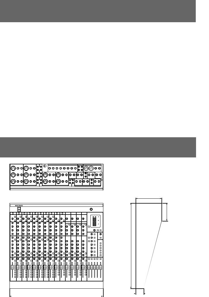
Dimensions
120 (43/4)
86 (31/2)
396 (155/8)
|
|
|
|
|
|
|
|
|
|
|
|
|
|
|
|
|
|
|
|
|
|
|
|
|
|
|
|
|
|
|
|
|
|
|
|
|
|
|
|
36 (17/16) |
Unit : mm (inch) |
|
|
430 (17) |
|
|
|
|
|
|
|
|
|
|
|
|
|
|
|
|
|
|
|
|
|||||||||||||||||||||
|
|
|
|
|
|
|
|
|
|
|
|
|
|
|
|
|
|
|
|
|
|
|
||||||||||||||||||||
2

Connections example
SR system connection
Keyboard
Compressor
AUDIO MIXER SRP-V110
CD or MD Player |
Microphone |
Compressor
Graphic Equalizer |
Graphic Equalizer |
|
Effector |
Power Amplifier |
Power Amplifier |
|
Main Speaker |
Dimensions |
characteristics Main |
|
|
example Connections |
Monitor Speaker
Recording system connection
Keyboard |
Compressor |
|
Multi Track Recorder |
CD or MD Player |
Microphone |
AUDIO MIXER SRP-V110
Monitor Speaker
Effector |
DAT(Master Recorder)
3
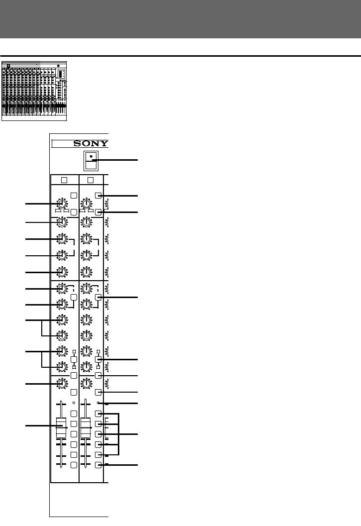
Name and function of each part
MONO INPUT section
2
5
6
7
8
9
!¼
!ª
!£
!¤
@¼
ON
POWER
OFF
|
1 |
|
2 |
|
|
|
LEVEL TAPE |
LEVEL TAPE |
LEVEL |
||||
|
LCF |
|
|
LCF |
|
|
+10 |
-40 |
+10 |
-40 |
|
+10 |
|
-10 |
-60 |
-10 |
-60 |
|
-10 |
|
|
HIGH |
|
HIGH |
|
||
-15 |
+15 |
-15 |
+15 |
|
-15 |
|
500 |
1.5K |
500 |
1.5K |
|
500 |
|
100 |
10K |
100 |
10K |
|
100 |
|
MID |
MID |
|||||
|
|
|
||||
-15 |
+15 |
-15 |
+15 |
|
-15 |
|
|
LOW |
|
LOW |
|
||
-15 |
+15 |
-15 |
+15 |
|
-15 |
|
|
|
|||||
|
AUX |
|
AUX |
|
||
|
1-2 |
|
|
1-2 |
|
|
1 |
MONI |
1 |
MONI |
1 |
||
2 |
2 |
|
||||
-‚∞ |
0 |
-‚∞ |
0 |
|
-‚∞ |
|
-‚∞ |
3 |
-‚∞ |
|
3 |
-‚∞ |
|
0 |
0 |
|
||||
-‚∞ |
4 |
-‚∞ |
|
4 |
-‚∞ |
|
0 |
0 |
|
||||
|
|
|
|
|||
|
5 7 |
|
5 |
7 |
|
|
-‚∞ |
0 |
-‚•∞ |
0 |
|
-‚∞ |
|
|
6 8 |
|
6 8 |
|
||
-‚∞ |
0 |
-‚∞ |
0 |
|
-‚˜ |
|
|
ON |
|
|
ON |
|
|
|
PFL |
|
|
PFL |
|
|
L |
R |
L |
R |
|
L |
|
ODD |
EVEN |
ODD |
EVEN |
|
ODD |
|
|
PEAK |
|
PEAK |
|
||
|
+10 |
|
+10 |
|
|
|
|
L-R |
|
|
L-R |
|
|
|
+5 |
|
+5 |
1-2 |
|
|
|
1-2 |
|
|
|
||
|
0 3-4 |
|
0 |
3-4 |
|
|
|
-5 |
|
-5 |
5-6 |
|
|
|
5-6 |
|
|
|
||
|
-10 |
|
-10 |
|
|
|
|
7-8 |
|
|
7-8 |
|
|
|
-20 |
|
-20 |
|
|
|
|
DIRECT |
|
DIRECT |
|
||
|
-‚∞ |
|
-‚∞ |
|
||
1
3
4
!Á
!¢
!°
!¦ !¥
!»
@Á
1POWER switch
When the switch is pressed to the ON side, the power is turned on.
2LEVEL control
This controls the input signals from the MIC or LINE connectors at a suitable level. When connected to the MIC connector, the input signal level can be controlled between –10 - –60 dBu, and when connected to the LINE connector, it can be controlled between +10 - –40 dBu. In order to control the input signal at a suitable level, set the meter to VU operation, press the PFL button of the channel to be controlled to display the signal level on the meter. In this state, turn the LEVEL control to control the signal so that 0VU display on the meter is lit sometimes.
3TAPE button
This switches the signal input from the MIC/LINE connectors to the TAPE IN connectors. Using this function, sounds, such as those from a multi-track recorder connected to the TAPE IN connectors, can be input to each channel without changing connections. (Channels 1 - 8 only)
4LCF (Low Cut Filter) button
This suppresses frequencies of 80 Hz or lower from the channel signal at 12 dB/oct (12 decibels per octave) when it is on. This function is very effective for removing “touch noise” that occurs when a microphone is being held, and “blow noise” caused by breathing.
5HIGH (High equalizer) level control
This varies the high equalizer level between
–15 - +15 dB. The equalizer is a 12 kHz shelving type.
6MID (Mid equalizer) frequency control
This varies the central frequencies of the mid equalizer between 100 Hz - 10 kHz.
7MID (Mid equalizer) level control
This varies the mid equalizer level between
–15 dB - +15 dB. The equalizer is a peaking type.
8LOW (Low equalizer) level control
This varies the low equalizer level between
–15 dB - +15 dB. The equalizer is a 40 Hz peaking type.
4

9AUX 1-2 PAN control
When turned towards the “1”, sound is shifted to the AUX 1 bus, and when turned in the “2” direction, it is shifted to the AUX 2 bus. When turned to the maximum in either direction, the output level is increased by +3 dB.
!¼ AUX 1-2 control
This controls the level that is sent to the AUX 1/2 buses. This AUX is a pre-fader (splitting the signal before the channel fader). It is used to create a separate balance mix and stereo monitor, as it does not depend on the position of the channel fader.
!Á MONI button
This changes the function of the AUX 1/2. When it is off, the AUX 1-2 PAN control and AUX 1-2 control operate as normal AUX. When it is on, the input signals from the TAPE IN connectors (or MIC/LINE connectors if the TAPE button is turned on) are sent to the AUX 1/2 buses. Sounds, such as those from a multi-track recorder that has been connected to the TAPE connectors, can be monitored through the AUX 1/2 output using this function. (MONO INPUT 1 - 8 only)
!¤ PAN control
When turned in the “L ODD” direction, sound is shifted to the MASTER L, GROUP 1, 3, 5 and 7 (odd channel) buses, and when turned in the “R EVEN” direction, sound is shifted to the MASTER R, GROUP 2, 4, 6, and 8 (even channel) buses. When turned to the maximum in either direction, the output level is increased by +3 dB.
!¦ PFL button
When turned on, the signals before they pass through the channel fader are routed to the PHONES connector and the MONITOR OUTPUT connectors, while displaying the level on the meter. When PFL buttons for a number of channels are pressed simultaneously, a mixed signal is routed. In this case, signals from channels whose AFL button is turned on are not output.
!¥ PEAK indicator
This is lit up whenever the signal level, after passing through the equalizer, is within 3 dB of the maximum level. When this LED is lit, the signal is excessive, and must be controlled using the LEVEL control. When the MIC connector is used, change it to the LINE connector.
!ª AUX 3 and 4 controls
These control the levels that are sent to the |
!» Assign buttons |
AUX 3 and 4 buses. These AUX’s can switch between |
When the L-R button is pressed, the signal is routed to |
the pre-fader and post fader (splitting the signal after it |
the MASTER L/R bus, and when the 1/2, 3/4, 5/6 or |
has passed through the channel fader) by using the |
7/8 buttons are pressed, the signal is routed to each |
PRE switch. (Refer to the MASTER section “2 PRE |
group bus. |
button”) |
|
!£ AUX 5/7 and 6/8 controls
These control the levels that are output to the
AUX 5/7 and 6/8 buses. These AUX’s are post faders. As a result, the AUX level changes depending on the position of the channel fader. This is used when sending signals to the effector, etc. to be connected externally.
!¢ AUX 7/8 button
These send the signals to the AUX 5/6 buses when turned off, and to the AUX 7/8 buses when turned on.
!° ON button
@¼ Channel fader
This sets the signal level for the channels.
@Á DIRECT button
When this button is turned off, the signals from the GROUP bus are output; and when it is turned on, the post fader signals from the MONO INPUT channels 1 - 8 are output to the GRP/DIRECT OUT 1 - 8 connectors.
* 0 dBu=0.775 V
When turned on, the signals from the channels are routed to each output. However, the PFL function is available even if this switch is turned off.
of function and Name part each
5
 Loading...