


SRX-R515P

Digital Cinema
Dual System
Operating Instructions
Before operating the unit, please read this manual and supplied Safety Regulations
thoroughly and retain it for future reference.
SRX-R515P
SRX-R515
LKRA-010
LKRA-011
LKRA-PCAB1
4-573-779-11(1)
© 2015 Sony Corporation

2
Table of Contents
Please Read This First .............................................. 3
Notations Used in This Guide ................................ 3
Manual Structure ................................................... 3
About License ........................................................ 3
USB HDD and USB Memory Devices That can be
Used on INGEST PORT 1/2 of This Unit ........... 3
Recognized Folder Names ..................................... 3
Overview
System Configuration Example ............................... 4
Part Names and Functions ....................................... 5
SRX-R515 Digital Cinema Projector .................... 5
XCT-S10 Digital Cinema Server ........................... 8
LKRA-007 Touch Panel Monitor ........................ 10
LKRA-011 3D filter and holder .......................... 11
LKRA-PCAB1 Projector Auto Calibration
Box ..................................................................... 12
Main Screen ......................................................... 13
Items to Check
Startup ..................................................................... 15
Turning on the Main Power on the Projectors ..... 15
Starting up the Server .......................................... 15
Logging Into the System ...................................... 15
Starting the Projectors .......................................... 16
Shutting Down the System ..................................... 17
Operations
Sequence of Operations .......................................... 18
Selecting the Projector to be Controlled ............... 18
Ingesting DCP .......................................................... 19
Ingesting from HDD via USB Connector ............ 19
Ingesting from HDD via CRU DATAPORT ........ 20
Ingesting via Network .......................................... 21
Ingesting KDM ........................................................ 21
Ingesting from a USB Flash Drive ....................... 21
Ingesting from a Network Folder ......................... 22
Playing Back CPL ................................................... 23
Calling up Screen Adjustment Data .................... 23
Selecting a CPL ................................................... 24
Playing Back CPL ................................................ 25
Creating an SPL ...................................................... 26
Creating an SPL ................................................... 26
Setting an Intermission in the SPL ...................... 28
Triggering SPL Playback Using GPI Signals ...... 29
Playing Back an SPL .............................................. 30
Selecting an SPL .................................................. 30
Playing Back an SPL ........................................... 30
Creating a Schedule ................................................ 30
Creating a Schedule ............................................. 30
Importing/Exporting Schedules ........................... 31
Projecting Images Using an External Playback
Device ....................................................................... 32
Manually Controlling Theater Facilities ............... 33
Others
Opening/Closing the 3D Filter ............................... 34
Opening the 3D Filter .......................................... 34
Closing the 3D Filter ........................................... 34
Calibrating the Screen ............................................ 35
Installing the Calibration Camera ........................ 35
LCD Panel Displays ............................................. 36
Preparation ........................................................... 36
Performing Calibration ........................................ 37
Disconnecting the Calibration Camera ................ 39
Attaching and Removing the Lens ........................ 40
Removing the Lens .............................................. 40
Attaching the Lens ............................................... 41
How to Read the Indicators ................................... 43
Troubleshooting ....................................................... 44
Error Code List (LKRA-PCAB1) .......................... 46
Specifications ........................................................... 48
SRX-R515 Digital Cinema Projector .................. 48
XCT-S10 Digital Cinema Server ......................... 48
LKRA-007 Touch Panel Monitor ........................ 49
LKRA-010 Dual System Accessory Kit .............. 49
LKRA-011 3D filter and holder ........................... 49
LKRA-PCAB1 Projector Auto Calibration
Box ..................................................................... 49
Trademarks
• The terms HDMI and HDMI High-Definition
Multimedia Interface, and the HDMI Logo are
trademarks or registered trademarks of HDMI Licensing
LLC in the United States and other countries.
• Other products or system names appearing in this
document are trademarks or registered trademarks of
their respective owners.
Further, the ® or ™ symbols are not used in the text.
• Reproduction or duplication, in whole or part, of the
operation manual supplied with the system without the
authorization of the right holder is prohibited under
copyright law.
• Sony assumes no responsibility for damages, loss of
income, or any claims from a third party arising out of
use of the system.
• Note that the specifications of the system are subject to
change for improvement without prior notice.

3
Please Read This First
Notations Used in This Guide
In this guide, the SRX-R515 Digital Cinema Projector is
referred to as the “projector,” the XCT-S10 Digital Cinema
Server is referred to as the “server,” the LKRA-007 Touch
Panel Monitor is referred to as the “touch panel monitor,”
and the system consisting of the above is referred to as the
“SRX-R515P.”
Manual Structure
The following manuals are provided for the digital cinema
dual system depending on the application.
Safety Regulations (SRX-R515P)
This includes safety instructions and precautions for using
the SRX-R515P.
Before Using This Unit (SRX-R515, LKRA-010,
LKRA-011, LKRA-PCAB1)
This includes safety instructions, precautions and
specifications for using the unit.
Installation Manual
This includes instructions on how to install the unit,
information on default settings, and instructions on how to
adjust the unit. Be sure to refer to this manual whenever
you need to change settings or readjust the unit after
installation.
Operating Instructions (this guide)
This includes instructions for screening controls in a
theater, how to create a screening schedule, how to change
lenses, projector part names, and product specifications.
Be sure to refer to this guide for instructions on daily
usage.
Maintenance Manual
This includes information such as instructions on periodic
inspection, maintenance, and cleaning.
Service Manual
This is intended for use by service personnel and includes
information on diagnosing malfunctions and instructions
on repair.
About License
Refer to “Software License Agreement.”
USB HDD and USB Memory Devices
That can be Used on INGEST PORT
1/2 of This Unit
USB HDD and USB memory devices that can be used on
INGEST PORT 1/2 of this unit are as follows.
• USB 2.0/3.0 (bus power capacity up to 1 A)
• Do not insert a bus-powered USB HDD and a USB
memory device into the two ports at the same time.
• USB HDD compatible file system
ext2, ext3
(Operation is not guaranteed for all types of USB HDD and
USB memory devices.)
Recognized Folder Names
Regarding the external directories (USB HDD, USB
memory devices, network folders, etc.) that are connected
to the unit, only folder names that consist of alphanumeric
characters will be recognized by the unit.
4
Overview
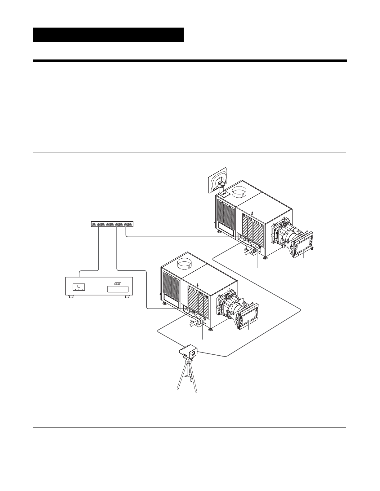
System Configuration Example
The digital cinema dual system consists of the following products.
• SRX-R515P Digital Cinema Projector Package
– SRX-R515 Digital Cinema Projector (main projector)
– XCT-S10 Digital Cinema Server
– LKRA-007 Touch Panel Monitor
• SRX-R515 Digital Cinema Projector (sub projector)
• LKRA-010 Dual System Accessory Kit: base and conduit kit
• LKRA-011 3D filter and holder: 3D projection kit
• LKRA-PCAB1 Projector Auto Calibration Box: camera for automatically calibrating convergence
LKRA-007
Main projector
LKRA-010
LKRA-011
to sub
projector
Sub projector
Network hub
XCT-S10
to main
projector
LKRA-010
LKRA-011
LKRA-PCAB1
Tripod
5
Part Names and Functions
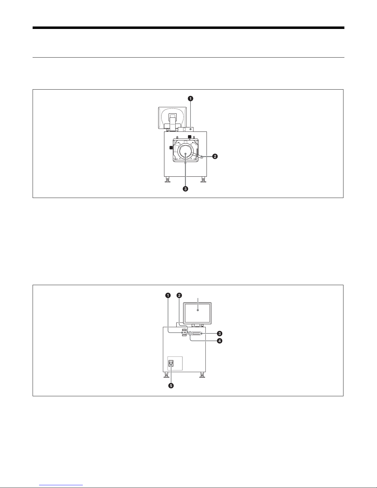
SRX-R515 Digital Cinema Projector
Front
a 8-inch duct attachment part
Used to attach an 8-inch exhaust duct.
b Lens fixing lever
Locks/unlocks the lens.
For further details, see “Attaching and Removing the
Lens” (page 40).
c Lens attachment part
Used to attach a separately-sold lens.
For further details, see “Attaching and Removing the
Lens” (page 40).
Rear
a Status lights
Shows the status of the projector.
For further details, see “How to Read the Indicators”
(page 43).
b EMERGENCY switch
Forcibly shuts off the lamp (equipped with a cooling
function).
c STATUS MESSAGE window
Displays various messages.
Touch Panel Monitor (page 10)
6
d Status indicators
Shows the status of the projector.
For further details, see “How to Read the Indicators”
(page 43).
e Power switch
Turns the projector’s main power on (|) or off (a).
When turning the power off
Wait for the lamp’s cooling process to complete
before turning the power switch off.
For further details, see “Shutting Down the System”
(page 17).
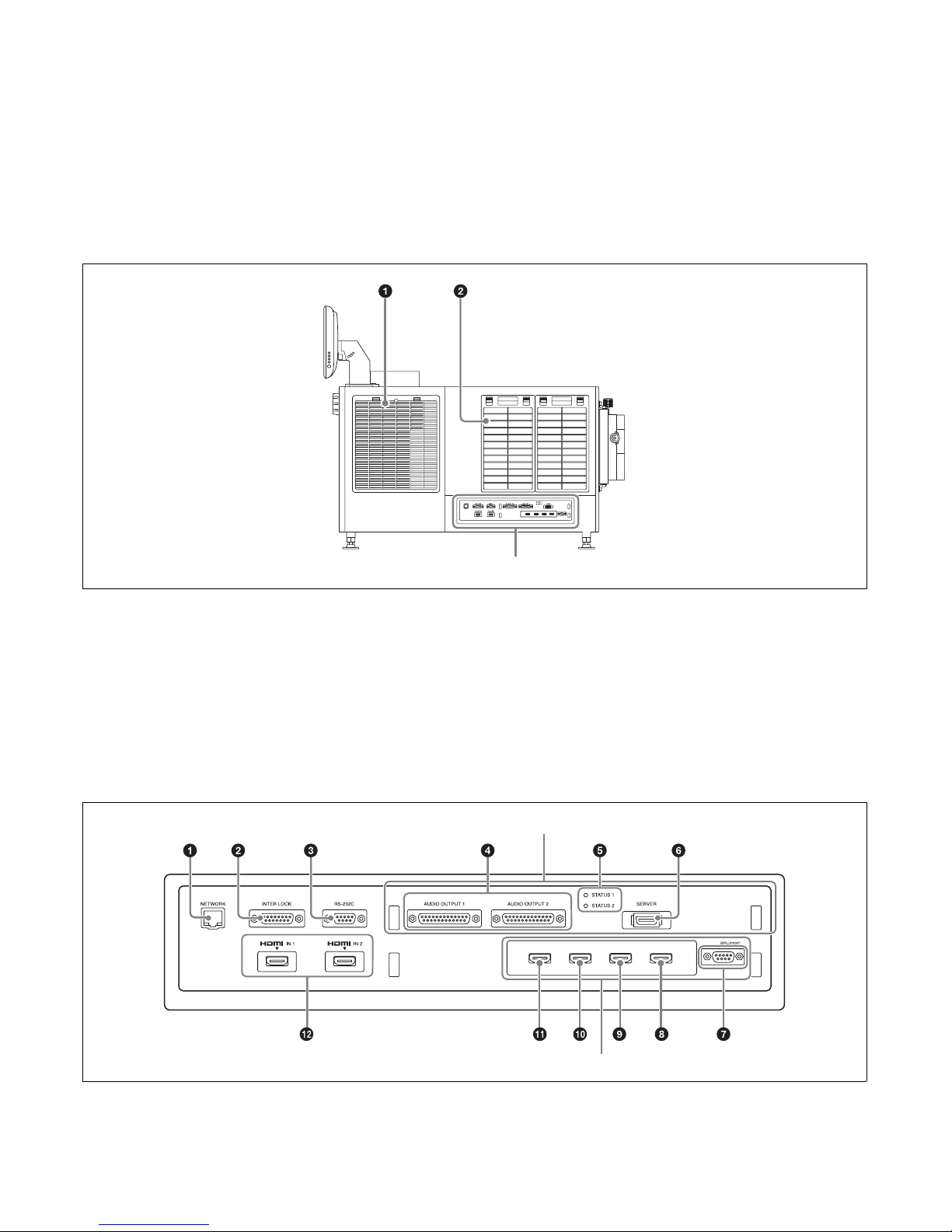
Left side
a Lamp access panel (lamp grill)/ventilation holes
(intake)/air filter
A lamp access panel (lamp grill), ventilation holes
(intake), and air filter are also located on the right side
of the unit.
For details on lamp replacement, refer to the
“Maintenance Manual.”
For details on air filter cleaning, refer to the
“Maintenance Manual.”
b Ventilation holes (intake)/air filter
For details on air filter cleaning, refer to the
“Maintenance Manual.”
Connector block: Main projector
Connector block
Integrated Media Block (IMB)
LKRA-010
7
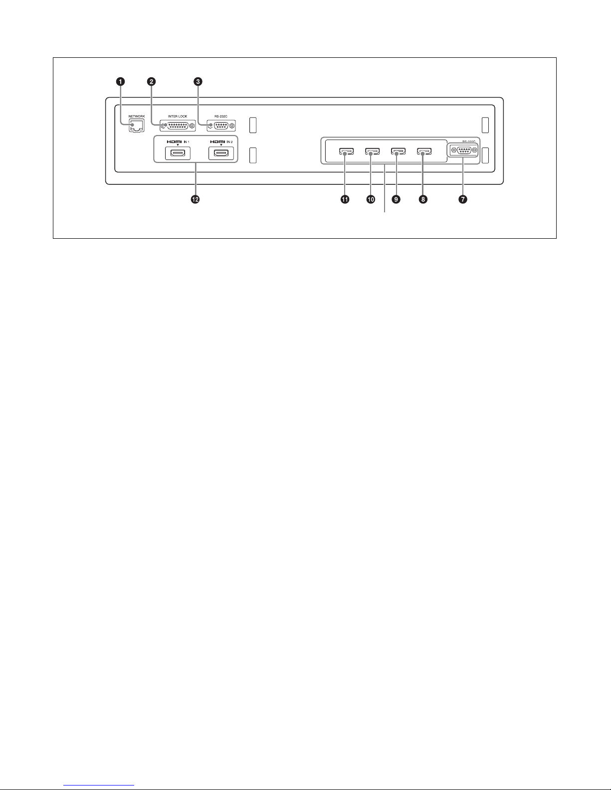
Connector block: Sub projector
a NETWORK connector (RJ-45 modular jack)
Used to connect to the server’s PRJ connector with the
supplied LAN cable.
b INTER LOCK connector (D-sub 15 pin, female)
This is not used in this system.
c RS-232C connector (D-sub 9 pin, female)
Used to connect to a LKRA-PCAB1.
Main projector: Use the supplied connection cable
to connect the CTRL2 connector on the LKRAPCAB1.
Sub projector: Use the supplied connection cable to
connect the CTRL1 connector on the LKRAPCAB1.
d AUDIO OUTPUT BAL/UNBAL (audio output
BAL/UNBAL) (AES/EBU) connector (D-sub 25
pin, female)
For connecting to an audio signal processor.
e STATUS 1/2 (Status 1/2) indicator
Shows the status of the projector.
For further details, see “How to Read the Indicators”
(page 43).
f SERVER connector
Used to connect to the server with the supplied PCI
express cable (2 m).
g RS-232C connector
This is not used in this system.
h Link B OUT connector
Connect this connector on the main projector to the
Link B IN connector on the sub projector.
This connector is not used on the sub projector.
i Link B IN connector
Connect this connector on the sub projector to the
Link B OUT connector on the main projector.
This connector is not used on the main projector.
j Link A OUT connector
Connect this connector on the main projector to the
Link A IN connector on the sub projector.
This connector is not used on the sub projector.
k Link A IN connector
Connect this connector on the sub projector to the
Link A OUT connector on the main projector.
This connector is not used on the main projector.
l HDMI IN 1/2 (HDMI input 1/2) connector
For HDMI signal input.
For details on signal format, see “HDMI signals”
(page 50).
LKRA-010
8
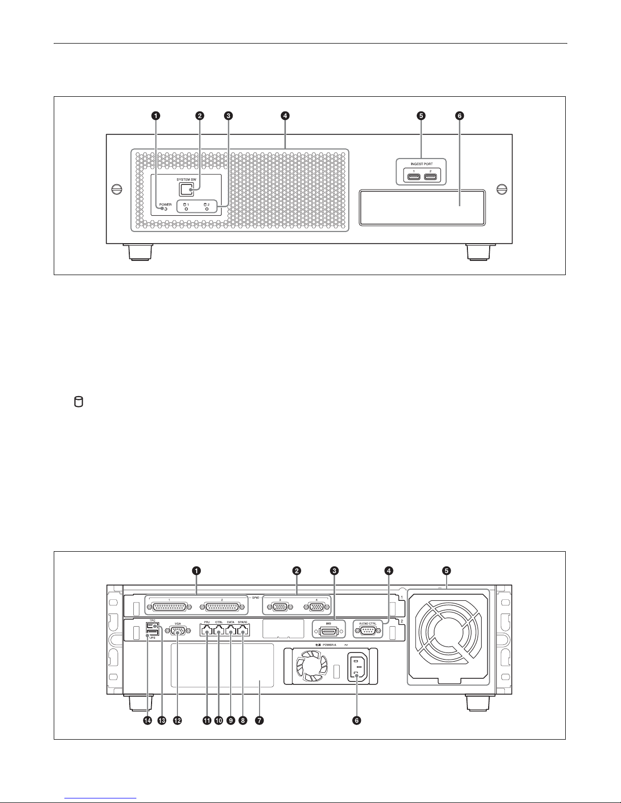
XCT-S10 Digital Cinema Server
Front
a POWER indicator
Shows the status of the server’s power.
For further details, see “How to Read the Indicators”
(page 43).
b SYSTEM SW switch
Starts up the server.
c (HDD) 1/2 indicator
Shows the status of the HDD.
For further details, see “How to Read the Indicators”
(page 43).
d Ventilation holes (intake)/air filter
For details on air filter cleaning, refer to the
“Maintenance Manual.”
e INGEST PORT 1/2 connector
For inserting HDD or USB memory to ingest DCP/
KDM.
These can only be used for a USB HDD or USB
memory device.
For further details, see “Ingesting from HDD via
USB Connector” (page 19), and “Ingesting from a
USB Flash Drive” (page 21).
f CRU DATAPORT
For inserting HDD to ingest DCP/KDM.
A CRU DATAPORT carrier is necessary to use the
CRU DATAPORT. For further details, contact
qualified Sony service personnel.
Rear

9
a GPIO 1/2 connector (D-sub 25 pin, female)
For connecting to an external device.
For further details, refer to the “Installation
Manual.”
b GPIO 3/4 connector (D-sub 15 pin, female)
For connecting to an external device.
For further details, refer to the “Installation
Manual.”
c IMB connector
Used to connect to the projector with the supplied PCI
express cable.
d AUDIO CTRL connector (D-sub 9 pin, male)
Used to control audio devices.
e Fan Unit
An exhaust fan.
f Power unit (-)
Connects with the power cord.
g Power unit B mount
For use with separately-sold expansion power units.
With both power units A and B attached, each can be
used as a redundant power source.
To connect a power unit, contact qualified Sony
service personnel.
h SPARE connector (RJ-45 modular jack)
For future expansions.
i DATA connector (RJ-45 modular jack)
Used to connect to a theater network (LAN) and allow
linking and data transfer with other systems.
Be sure to use a CAT6 or above for the LAN cable.
j CTRL connector (RJ-45 modular jack)
Used to connect to a theater network (LAN) and allow
linking and data transfer with other systems.
Be sure to use a CAT6 or above for the LAN cable.
k PRJ connector (RJ-45 modular jack)
Used to connect to the projector’s NETWORK
connector with the supplied LAN cable.
l VGA connector (D-sub 15 pin, female)
Used to connect to the touch panel monitor’s VGA
connector with the supplied VGA cable.
For connection instructions, refer to the “Installation
Manual.”
m TPC connector
Used to connect to the touch panel monitor’s TPC
connector with the supplied USB cable.
For connection instructions, refer to the “Installation
Manual.”
n UPS connector
Used to connect to an uninterruptible power supply
(UPS).
10
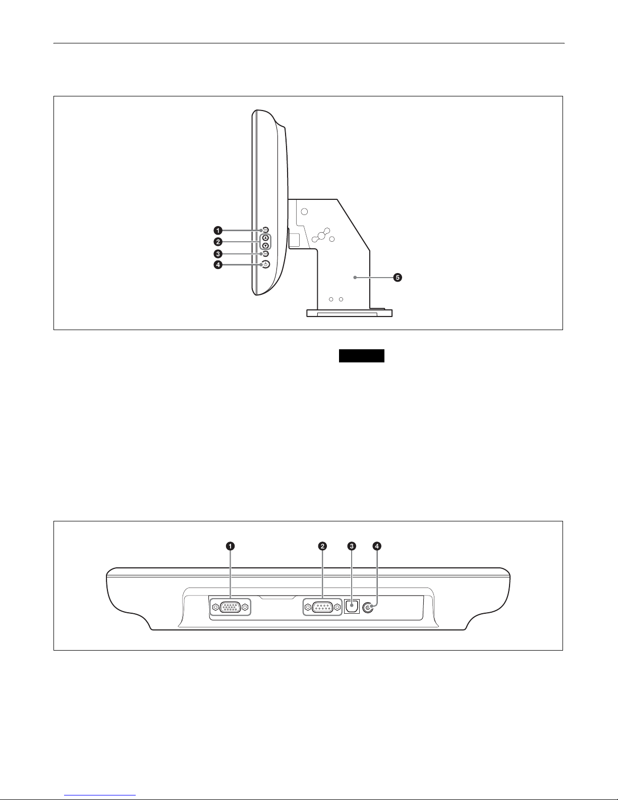
LKRA-007 Touch Panel Monitor
Right side
a MENU switch
Displays the menu.
b v / V switches
Used for moving the menu and setting new values.
c SELECT switch
Used for selecting the menu and items.
d 1 (Power) switch
Press this to turn the power on.
Press this again to turn the power off.
Caution
• When turning the power on, do not touch the touch
panel monitor screen. Doing so may prevent normal
operations after start-up.
• When the power is on, do not remove the touch
panel monitor cable.
e Monitor stand
This is equipped with a tilt mechanism.
The monitor’s position can be adjusted in the up,
down, left, and right directions.
Bottom
a VGA connector (D-sub 15 pin, female)
Used to connect to the server’s VGA connector with
the supplied VGA cable.
For connection instructions, refer to the “Installation
Manual.”
b RS-232C connector (D-sub 9 pin, female)
For service use.
11
c TPC connector
Used to connect to the server’s TPC connector with
the supplied USB cable.
For connection instructions, refer to the “Installation
Manual.”
d Power input connector
For connecting the supplied AC adapter.
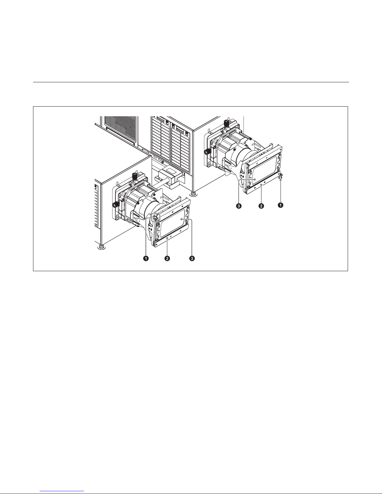
LKRA-011 3D filter and holder
(The 3D filters are installed to open to the left and right in the following sample illustration.)
a Lock pin
Locks the 3D filter holder.
b 3D filter holder
Holds the 3D filter.
c 3D filter
For details on using the 3D filter, see “Opening/Closing
the 3D Filter” (page 34).
12
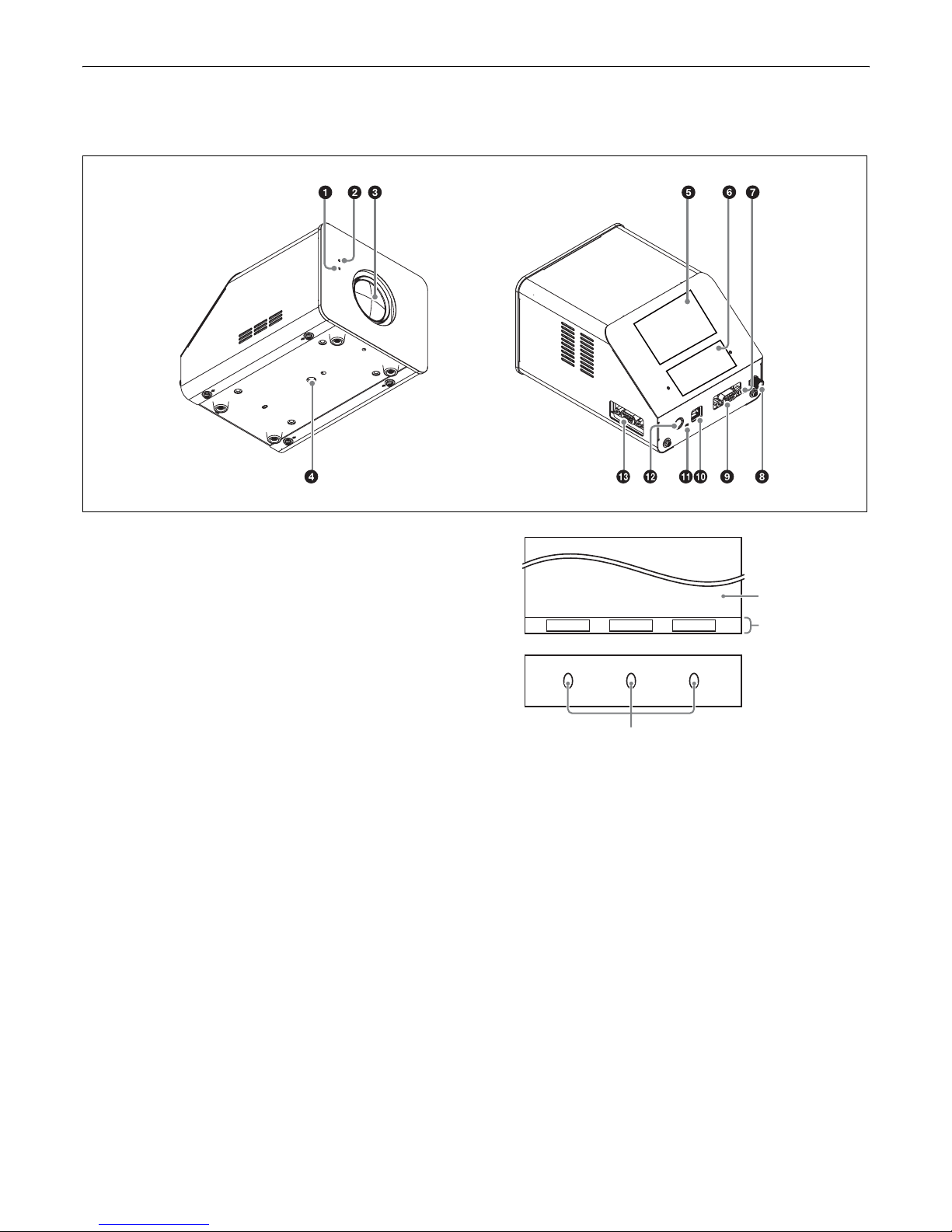
LKRA-PCAB1 Projector Auto Calibration Box
For details on how to use the LKRA-PCAB1, see “Calibrating the Screen” (page 35).
a Indicator B
Indicates the system status of the LKRA-PCAB1.
b Indicator A
Indicates that the hardware is initializing.
c Calibration camera
Measures the convergence of the two projectors.
d Tripod hole
e LCD panel
For details on the display screen, see “LCD Panel
Displays” (page 36).
f Touch sensor
Operate the LKRA-PCAB1 application by touching
the “buttons” that correspond with the functions that
appear in the function area of the LCD panel. Only the
LEDs that correspond to a currently controllable
function will light.
Touching the sensor with a pen or your fingernails
may result in erroneous operation. Be sure to touch
the sensor firmly with your fingertips.
g Projector status LED
Indicates the connection status between the LKRAPCAB1 and the projectors.
h GND connector
Connects to safety grounding.
i CTRL1 connector
Use the supplied connection cable to connect this to
the RS-232C connector on the sub projector.
j COM connector
This is currently not used. (Intended for future
expansion.)
k Power status LED
Indicates the power status.
Rear Front
F1 F2 F3
LCD panel
Function area
Various command
functions appear
for F1 to F3.
Touch sensor/LEDs
13
l DC IN connector
Connect the DC power cable of the supplied AC
adapter here.
m CTRL2 connector
Use the supplied connection cable to connect this to
the RS-232C connector on the main projector.
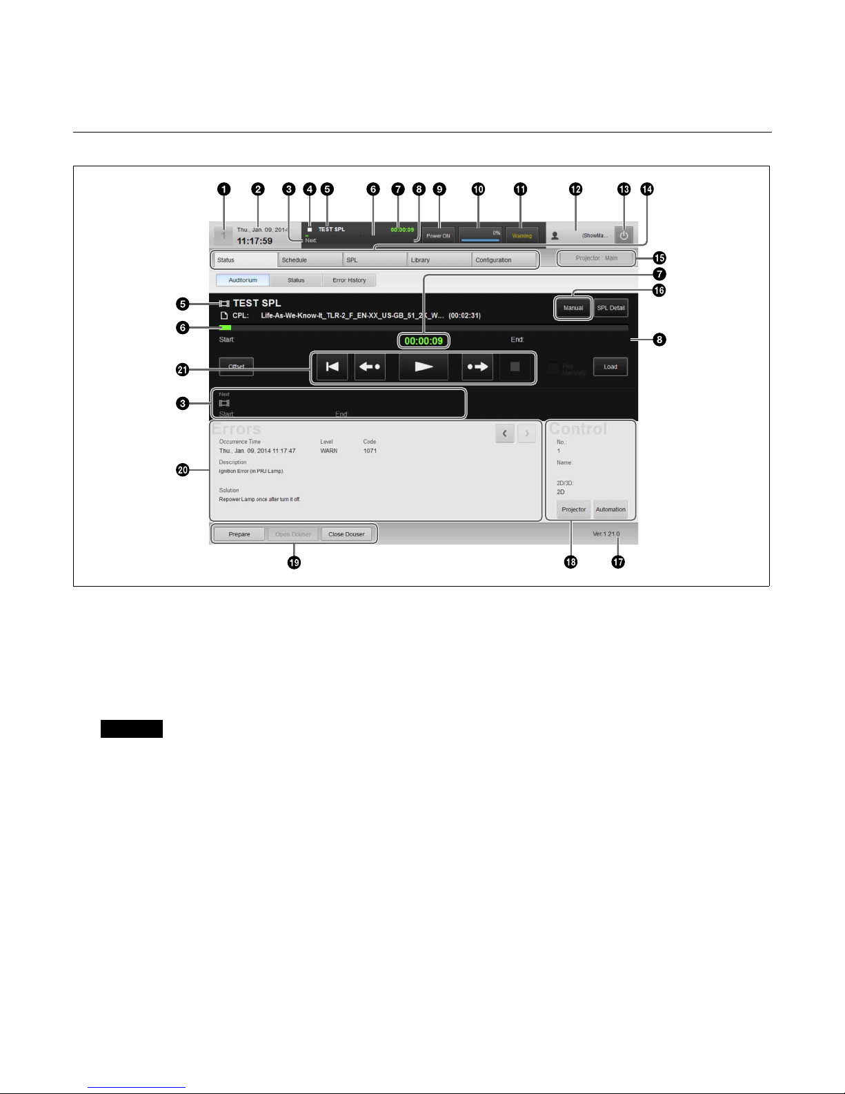
Main Screen
a Auditorium number
If a computer is being used to control multiple
auditoriums via a network, the auditorium numbers
will be displayed. Touch the number to display the
auditorium selection dialog box, and then select the
auditorium to operate.
Caution
Multiple auditoriums can only be controlled via a
network when a browser is used on a computer to
operate this unit. Do not control multiple auditoriums
using the touch panel monitor.
b Date display
Displays the current date (server date).
c Next SPL title for screening
d SPL playback status
Displays the SPL playback status using the same
icons used for the playback control buttons.
For details on the buttons, see “Playing Back CPL”
(page 25).
e Current SPL title
f Progress bar
Displays the progress of the title currently being
screened by CPL or SPL frames.
g Elapsed showing time
Displays an approximate time. Although there may be
a slight discrepancy in the units depending on system
conditions, this will not affect the actual screening.
h Scheduled start time of next SPL for screening /
time remaining until start
i Projector status indicator / control button
Indicates the operation status of the projector.
When you tap the button, the “Projector Lamp
Control” dialog box appears allowing you to operate
the projector.
j Job display button
Tap the button to switch to the “Job Status” screen in
the [Library] tab.
14
k Error display button
Displays the status of the device being controlled by
the server.
When you tap the button, the “Error History” screen
appears.
For details on the “Error History” screen, refer to the
“Maintenance Manual.”
Error: An error has occurred. (screening stops)
Warning: A non-fatal problem or error has occurred.
(screening continues)
Normal: The status is normal.
l Login user name
Displays the login user name.
m (Power) button
This enables shutdown, or logout from the projection
system. (page 17)
n Main menu
This menu provides access to all the functions on this
unit. The following menus are also available.
[Status]: Monitors the title being screened. Manual
playback can also be performed here.
For details on how to read the status, see “To
check installation/connections” (page 44).
[Schedule]: Creates a schedule.
See “Creating a Schedule” (page 30).
[SPL]: Creates an SPL (Show Playlist).
See “Creating an SPL” (page 26).
[Library]: Manages DCP (Digital Cinema Package)
or KDM (Key Delivery Message).
See “Ingesting DCP” (page 19), and “Ingesting
KDM” (page 21).
[Configuration]: Adjusts various settings.
For details on indicators, refer to the
“Installation Manual.”
o Projector selection button
Selects the projector (main or sub) to be controlled.
For details, see “Selecting the Projector to be
Controlled” (page 18).
p Playback mode display button
Displays the playback mode.
Tap the button to switch the playback mode.
Manual: Playback is performed manually.
Scheduled: Playback is performed using a schedule.
You can select the [Play Manually] checkbox to
perform playback manually even in schedule
mode.
q Version information
Displays the version information of the projector.
r Projector information display
Displays information about the projector.
See “Calling up Screen Adjustment Data” (page 23),
“Manually Controlling Theater Facilities”
(page 33).
s Shortcut button
Often-used functions are registered to this button.
Tap the button to activate a function.
Note
The following operations can be carried out in
[Prepare].
• Turn the lamp on
• Open the douser
• Cancel muting
• Cancel test pattern display
To register a function to the shortcut button, refer to
the “Installation Manual.”
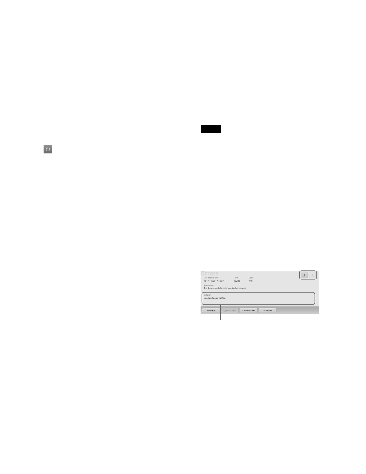
t Error information display
Displays the location and time an error occurred, an
explanation of the error and a solution.
When an error occurs, refer to [Solution] on the lower
left to deal with the problem.
When multiple errors or warnings have occurred, you
can check the next or previous warning by tapping [i]
or [I].
u Playback control button
In manual playback mode, you can control playback.
For details, see “Playing Back CPL” (page 25).
The solution will be displayed here. Follow the
instructions to deal with the problem.
15
Items to Check
Startup
When starting up the projection system, turn on the
projectors’ main power first, and then start up the server
and log in to the system.
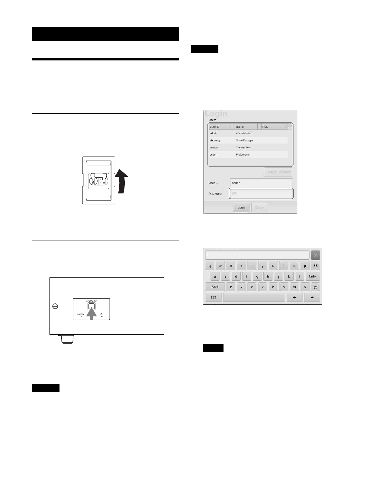
Turning on the Main Power on the
Projectors
Lower the power switch at the rear of each projector to the
on position (|) to turn on both projectors.
The power will turn on and the MAIN indicator and LAMP
indicator will turn solid red when the projectors enter
standby mode.
Starting up the Server
Press the SYSTEM SW switch on the server’s front to turn
it on.
The POWER indicator will blink green, and after start-up
is complete, it will turn solid green.
Once the server is on, the “Login” screen will be displayed
on the monitor.
Caution
• Do not start up the server with a USB device inserted in
INGEST PORT1/2 connector on the front of the server.
The USB device may not be recognized.
• When starting-up the server, do not touch the touch panel
monitor screen. Doing so may prevent normal operations
of the touch panel monitor after start-up.
Logging Into the System
Caution
It is necessary to pre-register as a user to log in to the
projection system.
For further details, refer to the “Installation Manual.”
1
Tap your own user name in the user list, and then tap
the [Password] column.
A virtual keyboard for entering your password will be
displayed.
2
Enter your password, and then tap [Enter].
If you make a mistake when entering your password,
tap [BS] to delete the last character.
When the password is entered, it will be displayed
masked above the keyboard.
Notes
• Startup of the projection system will take some
time. Startup processes for the server continue even
after the user list appears. Lists, such as those for
ingested CPLs, will not appear until the startup
processing is complete.
• You can change your password.
See “To change your login password” (page 16).
The virtual keyboard will disappear, and asterisks (*)
will be entered in the [Password] column.
16
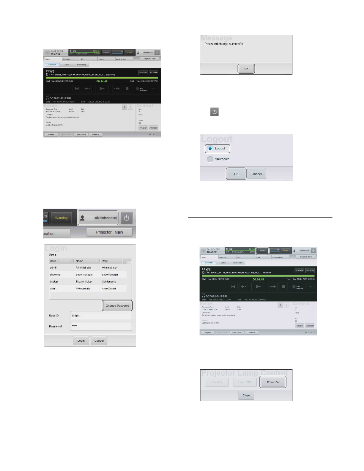
3
Tap [Login].
Once you log in to the system, the “Status” screen will
be displayed.
Proceed to “Starting the Projectors” (page 16).
To change your login password
As a user, you can change your own password.
1
Tap the area where the user name is displayed at the
top right of the screen to display the “Login” screen,
and tap [Change Password].
A screen for changing your password will be
displayed.
2
Enter the old password and new password, and then
tap [OK].
Tap each field to display a virtual keyboard, and enter
the necessary information.
3
Tap [OK] when the confirmation screen appears.
Your password will be changed.
Changing the login user
1
Tap on the upper right of the screen.
2
Select [Logout], and then tap [OK].
The “Login” screen will be displayed.
3
Change the user and log in.
Starting the Projectors
1
In the “Status” screen, tap [Standby].
The “Projector Lamp Control” dialog box will be
displayed.
2
Tap [Power ON].
The MAIN indicators on the rear of the projectors will
turn solid green, and the LAMP indicators will blink
green.
 Loading...