


C91GMXAT
Table of contents
 Loading...
Table of contents
3
1. PRECAUTIONS FOR USE .................................................................................4
2. INSTALLING THE APPLIANCE .........................................................................6
3. ADAPTATION TO DIFFERENT TYPES OF GAS ...........................................10
4. FINAL OPERATIONS ......................................................................................12
5. GETTING TO KNOW YOUR COOKER ...........................................................13
6. DESCRIPTION OF FRONT PANEL CONTROLS ...........................................14
7. USING THE HOB .............................................................................................15
8. USING THE OVEN ...........................................................................................16
9. AVAILABLE ACCESSORIES ..........................................................................18
10. ELECTRONIC PROGRAMMER ....................................................................19
11. CLEANING AND MAINTENANCE ................................................................21
12. EXTRAORDINARY MAINTENANCE ............................................................23
Thank you for choosing our product.
We advise you to read this manual carefully. It contains all necessary instructions for maintaining
unaltered the appearance and functional qualities of the cooker.
INSTRUCTIONS FOR THE INSTALLER: these are intended for the authorized person who is to check
the gas supply system and install, commission and test the appliance.
INSTRUCTIONS FOR THE USER: these provide recommendations for use, a description of the controls
and the correct procedures for cleaning and maintaining the appliance.
Precautions for use
4
1. PRECAUTIONS FOR USE
THIS MANUAL IS AN INTEGRAL PART OF THE APPLIANCE. TAKE GOOD CARE OF IT AND KEEP
IT TO HAND THROUGHOUT THE COOKER'S LIFE CYCLE. WE URGE YOU TO READ THIS
MANUAL AND ALL THE INFORMATION IT CONTAINS CAREFULLY BEFORE USING THE
APPLIANCE. ALSO KEEP ALL THE NOZZLES PROVIDED IN A SAFE PLACE. INSTALLATION MUST
BE CARRIED OUT BY QUALIFIED PERSONNEL IN ACCORDANCE WITH THE REGULATIONS IN
FORCE. THIS APPLIANCE IS INTENDED FOR HOUSEHOLD USE AND COMPLIES WITH THE
RELEVANT REGULATIONS. THE APPLIANCE HAS BEEN BUILT TO CARRY OUT THE
FOLLOWING FUNCTIONS: COOKING AND HEATING FOODS; ALL OTHER USES ARE
CONSIDERED IMPROPER.
THE MANUFACTURER DECLINES ALL RESPONSIBILITY FOR IMPROPER USE.
TO BE INSTALLED ONLY BY AN AUTHORIZED PERSON.
NEVER LEAVE PACKAGING RESIDUES UNATTENDED IN THE HOME. SEPARATE WASTE
PACKAGING MATERIALS BY TYPE AND CONSIGN THEM TO THE NEAREST SEPARATE
DISPOSAL CENTRE.
REPLACED APPLIANCES MUST BE TAKEN TO A SPECIAL GARBAGE COLLECTION CENTRE.
THE APPLIANCE MUST BE CONNECTED TO EARTH IN COMPLIANCE WITH ELECTRICAL
SYSTEM SAFETY REGULATIONS.
THE PLUG TO BE CONNECTED TO THE POWER SUPPLY LEAD AND THE RELATIVE SOCKET MUST
BE OF THE SAME TYPE AND COMPLY WITH THE RELEVANT REGULATIONS.
THE SOCKET MUST BE ACCESSIBLE AFTER THE APPLIANCE IS BUILT IN.
NEVER DISCONNECT THE PLUG BY PULLING ON THE POWER SUPPLY LEAD.
IMMEDIATELY AFTER INSTALLATION, CARRY OUT A QUICK TEST ON THE APPLIANCE FOLLOWING
THE INSTRUCTIONS PROVIDED LATER IN THIS MANUAL. SHOULD THE APPLIANCE NOT FUNCTION,
DISCONNECT IT FROM THE SUPPLY AND CALL THE NEAREST TECHNICAL ASSISTANCE CENTRE.
NEVER ATTEMPT TO REPAIR THE APPLIANCE YOURSELF.
AFTER EACH USE OF THE APPLIACE, ALWAYS CHECK THAT THE CONTROL KNOBS ARE TURNED
TO (OFF)
NEVER PLACE FLAMMABLE OBJECTS IN THE OVEN: IF IT SHOULD ACCIDENTALLY BE SWITCHED
ON, THIS MIGHT CAUSE A FIRE.
THE NAMEPLATE WITH THE TECHNICAL DATA, SERIAL NUMBER AND MARK IS IN A VISIBLE
POSITION INSIDE THE STORAGE COMPARTMENT.
THE PLATE MUST NEVER BE REMOVED.
NEVER PLACE PANS WITH BOTTOMS WHICH ARE NOT PERFECTLY FLAT AND SMOOTH ON THE
HOB GRIDS.
DURING USE THE APPLIANCE BECOMES VERY HOT. TAKE CARE NEVER TO TOUCH THE HEATING
ELEMENTS INSIDE THE OVEN. TO AVOID BURNS AND SCALDS CHILDREN SHOULD BE KEPT AWAY.
IF THE APPLIANCE IS TO BE POSITIONED ON A PLATFORM IT MUST BE INSTALLED IN SUCH A WAY
AS TO PREVENT IT FROM SLIPPING OFF THE FORMER.
INSTALL THE APPLIANCE SO THAT WHEN DRAWERS OR DOORS OF UNITS INSTALLED AT HOB
HEIGHT ARE OPENED, ACCIDENTAL CONTACT WITH PANS ON THE HOB IS NOT POSSIBLE.
Precautions for use
5
WARNING - IN ORDER TO PREVENT ACCIDENTAL TIPPING OF THE APPLIANCE, FOR EXAMPLE
BY A CHILD CLIMBING ONTO THE OPEN OVEN DOOR, THE STABILIZING MEANS MUST BE
INSTALLED.
PLEASE REFER TO INSTRUCTIONS FOR INSTALLATION.
NEVER USE PANS OR GRIDDLE PLATES WHICH PROJECT BEYOND THE OUTSIDE EDGE OF THE
HOB.
THE APPLIANCE IS NOT INTENDED FOR USE BY YOUNG CHILDREN OR INFIRM PERSONS UNLESS
THEY HAVE BEEN ADEQUATELY SUPERVISED BY A RESPONSIBLE PERSON TO ENSURE THEY CAN
USE THE APPLIANCE SAFELY. YOUNG CHILDREN SHOULD BE SUPERVISED TO ENSURE THAT
THEY DO NOT PLAY WITH THE APPLIANCE.
DO NOT SPRAY AEROSOLS IN THE VICINITY OF THIS APPLIANCE WHILE IT IS IN OPERATION.
WHERE THIS APPLIANCE IS INSTALLED IN MARINE CRAFT OR CARAVANS, IT SHALL NOT
BE
USED AS A SPACE HEATER.
BEFORE THE APPLIANCE IS PUT INTO OPERATION, ALL THE LABELS AND PROTECTIVE FILMS
APPLIED INSIDE OR OUTSIDE MUST BE REMOVED.
DO NOT MODIFY THIS APPLIANCE.
DO NOT STORE FLAMMABLE MATERIALS IN THE APPLIANCE STORAGE DRAWER OR NEAR
THIS APPLIANCE.
THE INSTRUCTIONS PACKAGED WITH THIS APPLIANCE CONTAIN IMPORTANT INFORMATION
ABOUT INSTALLATION AND USE.
UNSUITABLE FOR USE IN MARINE CRAFT, CARAVANS OR MOBILE HOMES, UNLESS EACH
BURNER IS FITTED WITH A FLAME SAFEGUARD
IN CASE OF SERVICE, CONTACT YOUR NEAREST SERVICE AGENT OR DISTRIBUTOR LISTED
ON THE WARRANTY CARD.
The manufacturer declines all responsibility for injury or damage caused by failure to comply with the
above regulations or deriving from tampering with even just one part of the appliance and the use of
non-original spare parts.
Instructions for the installer
6
2. INSTALLING THE APPLIANCE
IIt is the law that all gas appliances are installed by authorised persons. Clearance around the cooker
must comply with the requirements of AS5601.
2.1 Electrical connection
After making the electrical and gas connections, level the the appliance on the ground by means of its
four adjustable feet. For good cooking results, the appliance must be properly levelled. Depending on
the model you have purchased, the foot height adjustment range may vary from 70 to 95 mm and from
110 to 160 mm. These heights refer to the distance between the highest point of the foot (fixed part) and
the lowest point (movable part which rests on the floor).
2.2 Electrical connection
Make sure that the power line voltage matches the specifications indicated on the rating plate located
inside the storage compartment.
This rating plate must never be removed.
The plug on the end of the power supply cable and the wall socket must be of the same type (in
compliance with the relevant national standards). Check that the power supply line is properly earthed.
The use of reductions, adapters or junctions is not recommended.
The appliance's power supply line must be fitted with an omnipolar breaking device with contact gap of
at least 3 mm, located in an easily accessible position close to the appliance itself.
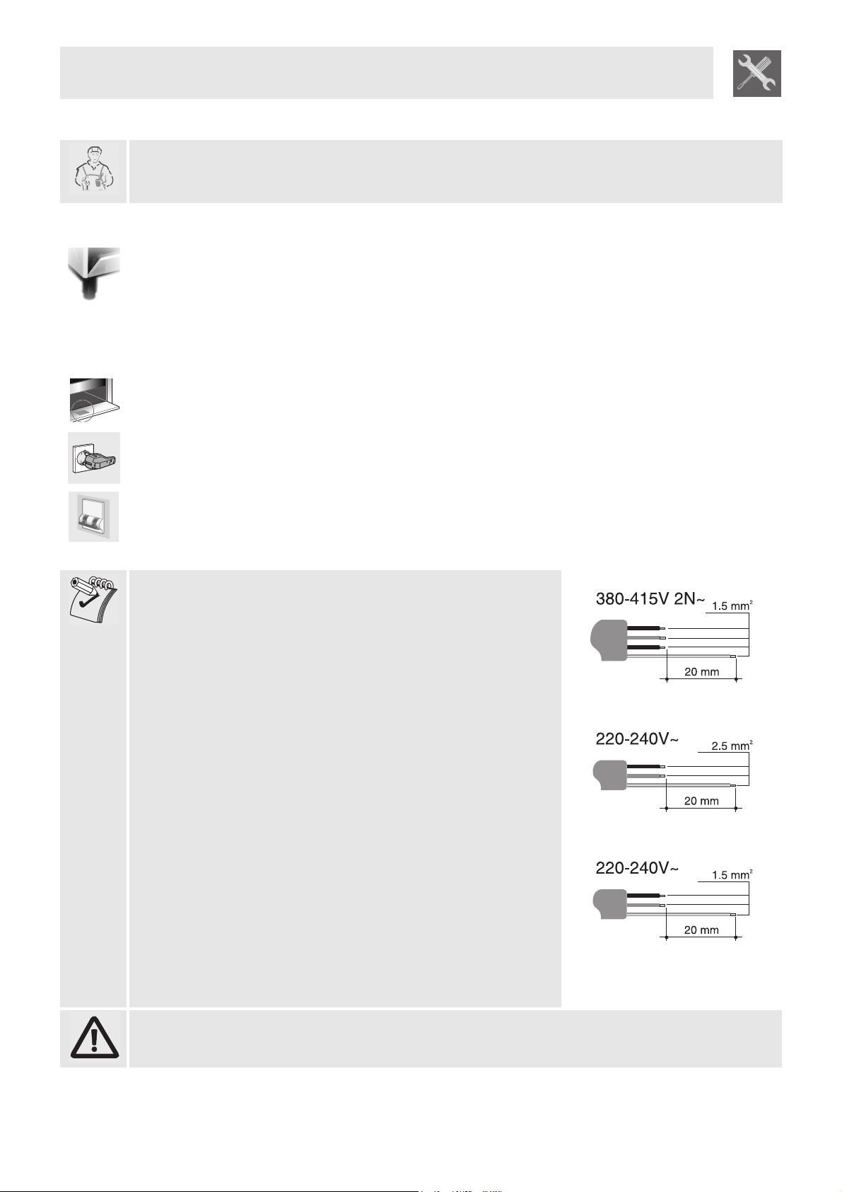
Only for 90 cm models:
For operation on 380-415V 2N~: use an H05V2V2-F type five-core
cable (5 x 1.5 mm
2
).
For operation on 220-240V~: use an H05V2V2-F type four-core
cable (3 x 2.5 mm
2
).
Only for 60 - 70 cm models:
For operation on 220-240V~: use an H05V2V2-F type three-core
cable (3 x 1.5 mm
2
).
The earth wire (yellow-green) must be at least 20 mm longer than
the other wires at the end for connection to the appliance.
The manufacturer declines all responsibility for damage to persons or things caused by non-
observance of the above prescriptions.
Instructions for the installer
7
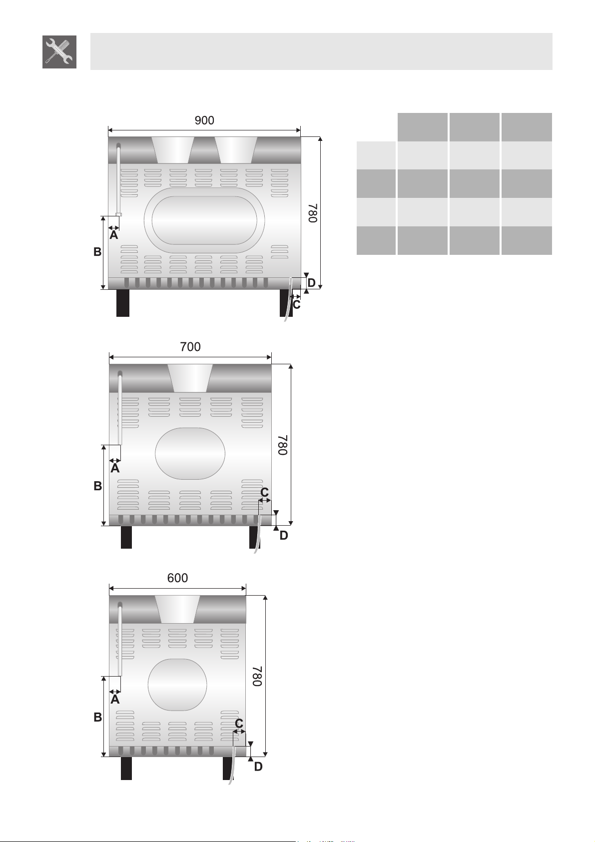
Overall dimensions: location of gas and electrical connection points (all measures in mm).
90 cm 70 cm 60 cm
A 60 110 55
B 600 600 600
C 110 157 100
D 145 145 145
Instructions for the installer
8
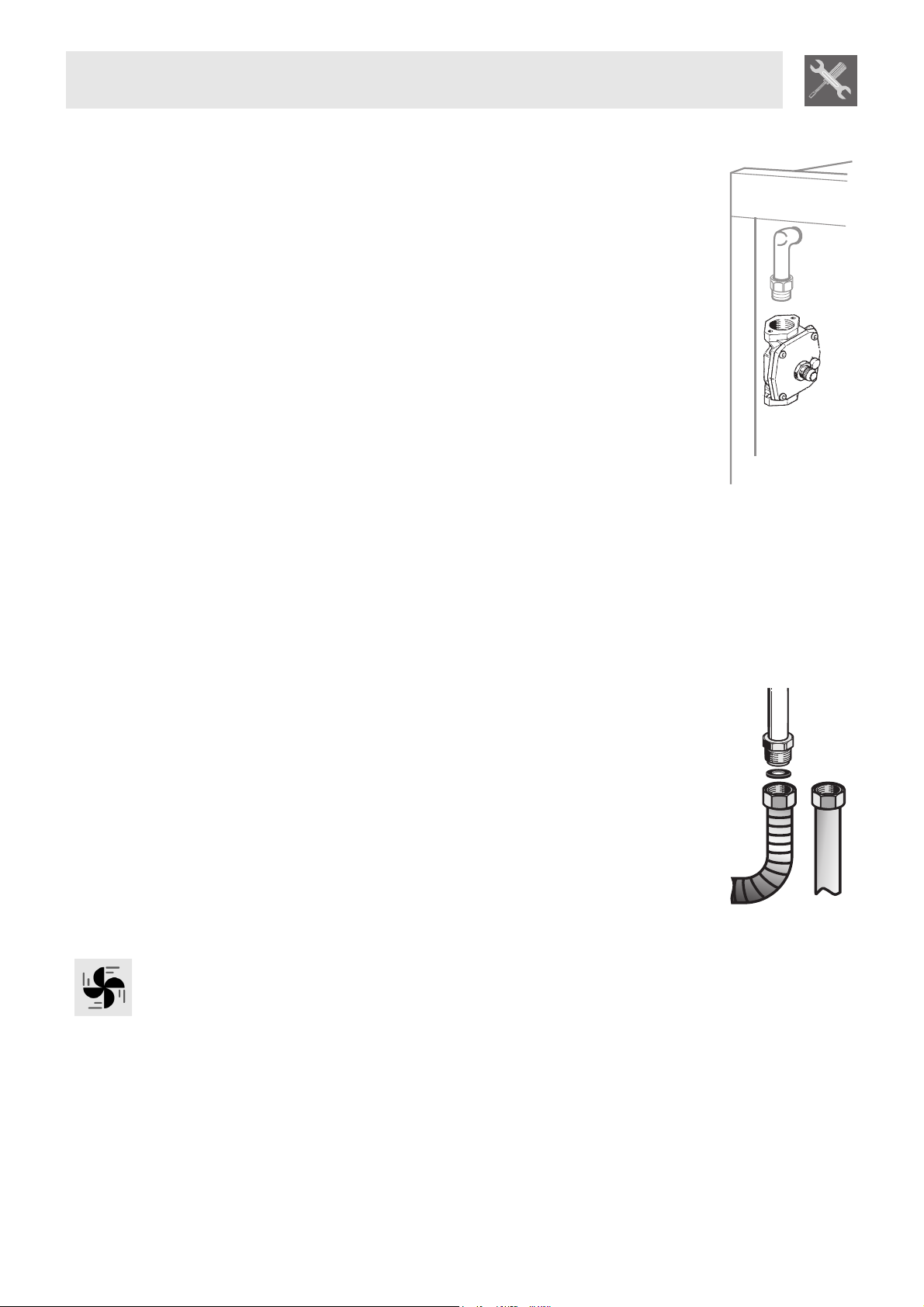
2.3 Gas connection
This appliance is suitable for installation with Natural Gas or ULPG (propane). Refer
to page 13 for the relevant burner pressure and appropriate injector sizes. When the
appliance is to be connected to Natural Gas then the pressure regulator supplied
must be fitted to the gas inlet. A test point (for checking the gas pressure) is supplied
either with the regulator or as a separate fitting in the case of LPG (propane)
appliances.
Connection of the appliance to the gas supply must be in accordance with the
requirements of AS5601. A ½” BSP connector at the inlet is recommended and the
gas supply line to the appliance must be of adequate length to allow sufficient
withdrawal of appliance for service or disconnection and be:
1 annealed copper pipe or;
2 Flexible hose according to AS/NZ1869 & be at least Class “B”, 10 mm diameter,
max length 100 mm.
The cooker must be installed with provision to allow the gas to be turned off and
disconnected for servicing and removal of the appliance as required from the gas
supply.
Before the cooker is operated make certain all relevant parts are placed in the correct
position.
When the installation is completed the installation connections of cooker will require
to be leak tested, the burner operating pressure and flame checked and adjusted.
Warranty service calls do not cover these adjustments!
To check the operating pressure of the appliance it is recommended at least 2 large
size burners are used. Ensure appliance is secured to wall when installation is
completed.
N.G. The regulator supplied must be fitted to the ½ BSP thread at the rear of the
appliance. An approved manual shut-off valve must be installed. The N.G. regulator
must be checked and adjusted to 1.0kPa after installation.
U.L.P.G. Can be connected to the inlet fitting directly. The pressure must be checked
to ensure it is operating at 2.75kPa. A separate test point fitting must be installed
between the piping & the appliance for the pressure to be checked to ensure it is
operating at 2.75kPa.
2.4 Ventilation requirements
Caution – This cooker may only be installed and operated in rooms permanently ventilated in
accordance with current regulations. For proper operation of a gas appliance it is essential for the air
necessary for combustion of the gas to be able to flow naturally into the room. Air must flow directly into
the room through openings in its outside walls. This (these) opening (s) must have a free passage cross-
section of at least 100 cm2, or 200 cm2 for appliances not equipped with gas safety device. These
openings must be constructed so that they cannot be obstructed indoors or outdoors, and should
preferably be close to the floor on the side opposite to the combustion gas discharge point. If it is not
possible to make the openings in the room where the cooker is installed, the necessary air may be taken
from an adjoining room, proveded it is not a bedroom or a room with fire risk.
Instructions for the installer
9
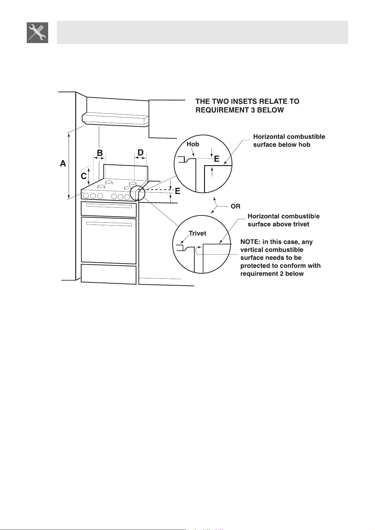
2.5 Clearance above
and around domestic
cookers
Extract from AS5601
REQUIREMENTS
1 Overhead clearances – (Measurement A)
Range hoods and exhaust fans shall be installed in accordance with the manufacturer’s instructions.
However, in no case shall the clearance between the highest part of the hob of the cooking appliance
and a range hood be less than 600 mm or, for an overhead exhaust fan, 750 mm.
Any other downward facing combustible surface less than 600 mm above the highest part of the hob
shall be protected for the full width and depth of the cooking surface area in accordance with Clause
5.12.1.2. However, in no case shall this clearance to any surface be less than 450 mm.
2 Side clearances – (Measurements B & C)
Where B, measured from the periphery of the nearest burner to any vertical combustible surface, is
less than 200 mm, the surface shall be protected in accordance with Clause 5.12.1.2 to a height C of
not less than 150 mm above the hob for the full dimension (width or depth) of the cooking surface
area. Where the cooking appliance is fitted with a ‘splashback’, protection of the rear wall is not
required.
3 Additional requirements for Freestanding and Elevated Cooking Appliaces – (Measurements D & E)
Where D, the distance from the periphery of the nearest burner to a horizontal combustible surface is
less than 200 mm, then E shall be 10 mm or more, or the horizontal surface shall be above the trivet.
See insets above.
Instructions for the installer
10
NOTES
1 Requirement 3 does not apply to a freestanding or elevated cooking appliance which is designed to
prevent flames or the cooking vessels from extending beyond the periphery of the appliance.
2 The ‘cooking surface area’ is defined as that part of the appliance where cooking normally takes place
and does not include those parts of the appliance containing control knobs.
3 For definition of hob, see Clause 1.4.64.
4 For definition of trivet, see Clause 1.4.109.
5 Consideration is to be given to window treatments when located near cooking appliances. See
Clause 5.3.4.
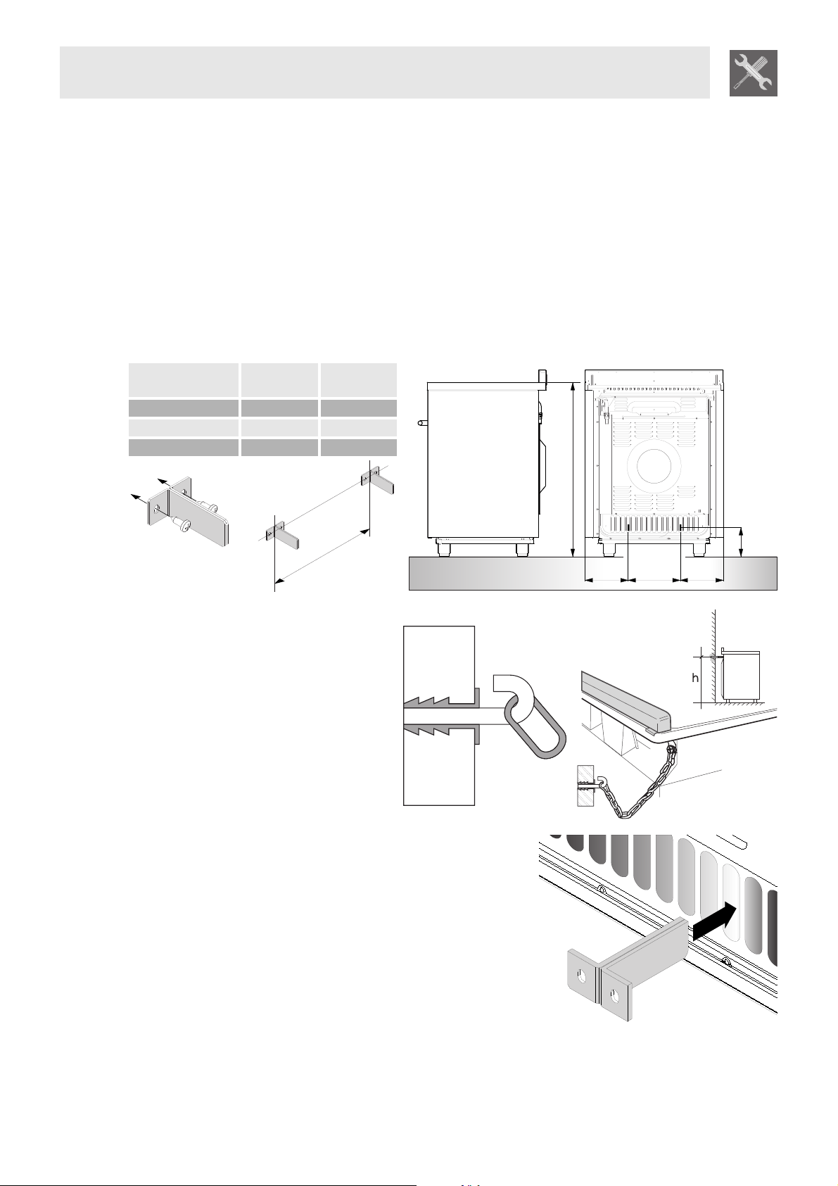
2.6 Instruction for wall fixing
1 Fasten the two wall brackets to the wall taking care to comply with the centre distances and
measurements indicated in the images below. The dimensions are given in mm.
cooker
dimensions (cm)
A B
60 262 168
70 262 218
90 457 220.5
2 Attach the chain to the cooker
3 Stretch out the chain attached to the
cooker horizontally so that the other
end touches the wall.
4 Mark the wall in the position where the
hole is to be drilled.
5 Drill the hole, insert a wall plug and
attach the chain.
6 Once these operations are completed, push the appliance
against the wall taking care to insert the wall brackets
correctly in the slots on the back of the cooker.
A
170
900
BB
A
Instructions for the installer
11
3. ADAPTATION TO DIFFERENT TYPES OF GAS
Before performing any operations requiring access to powered parts, switch off the power supply to the
appliance.
The cooker hob is preset for natural gas at a pressure of 1.0 KPa. In the case of operation with other
types of gas the burner nozzles must be changed and the minimum flame adjusted on the gas taps. To
change the nozzles, proceed as described below.
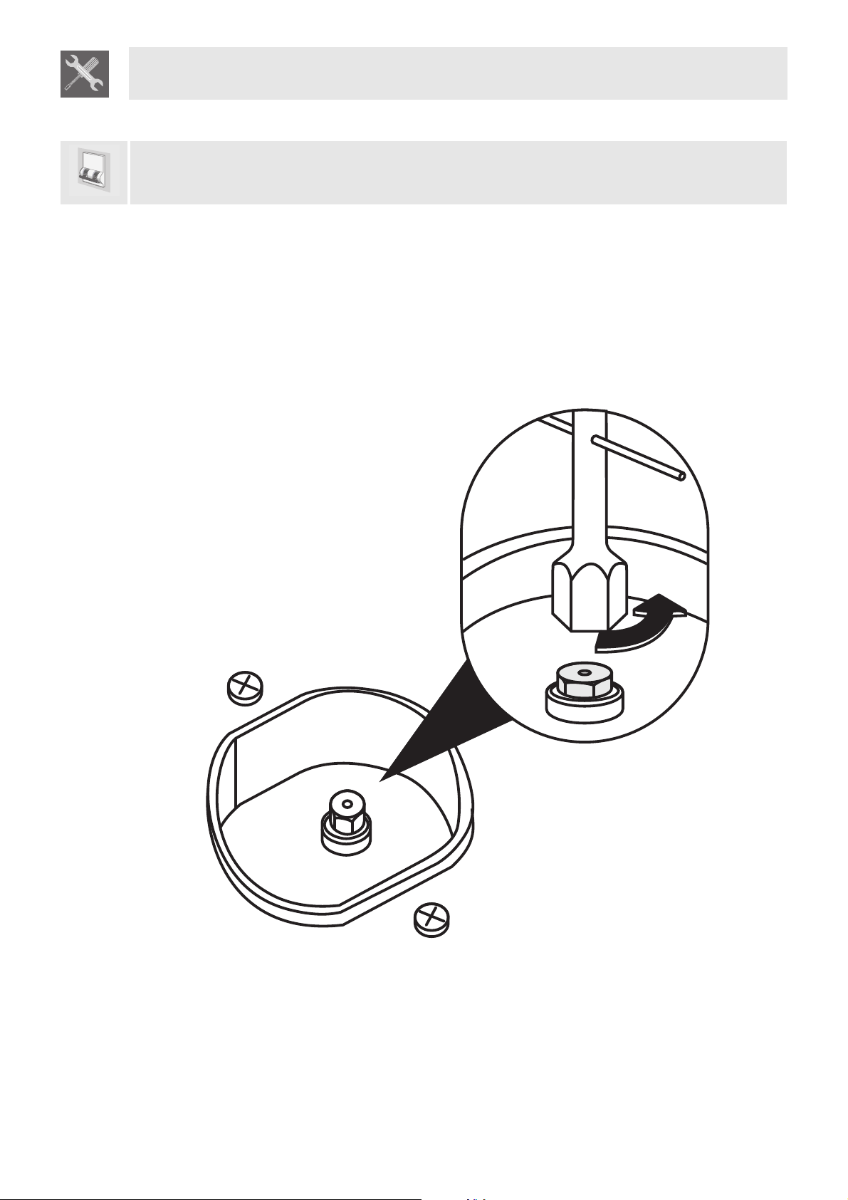
3.1 Changing nozzles
This operation does not require the primary air to be adjusted.
1 Extract the grids and remove all the caps and flame-spreader crowns;
2 Unscrew the burner nozzles with a 7 mm socket wrench;
3 Replace the nozzles according to the type of gas to be used and the description in paragraph "3.2
Burner and nozzle characteristics table";
4 Replace the burners in the correct position.
Loading...